Installation and Operation Manual
3. Installation
ATTENTION! Do not carry out installation work when there are strong winds.
Secure yourself and other workers to avoid falling. Secure work materials to prevent articles from falling.
Create a work zone to avoid accidents.
WARNING! The following paragraphs are very important. Failure to comply with these instructions can
lead to system underperformance and will void the Autarco kWh guarantee.
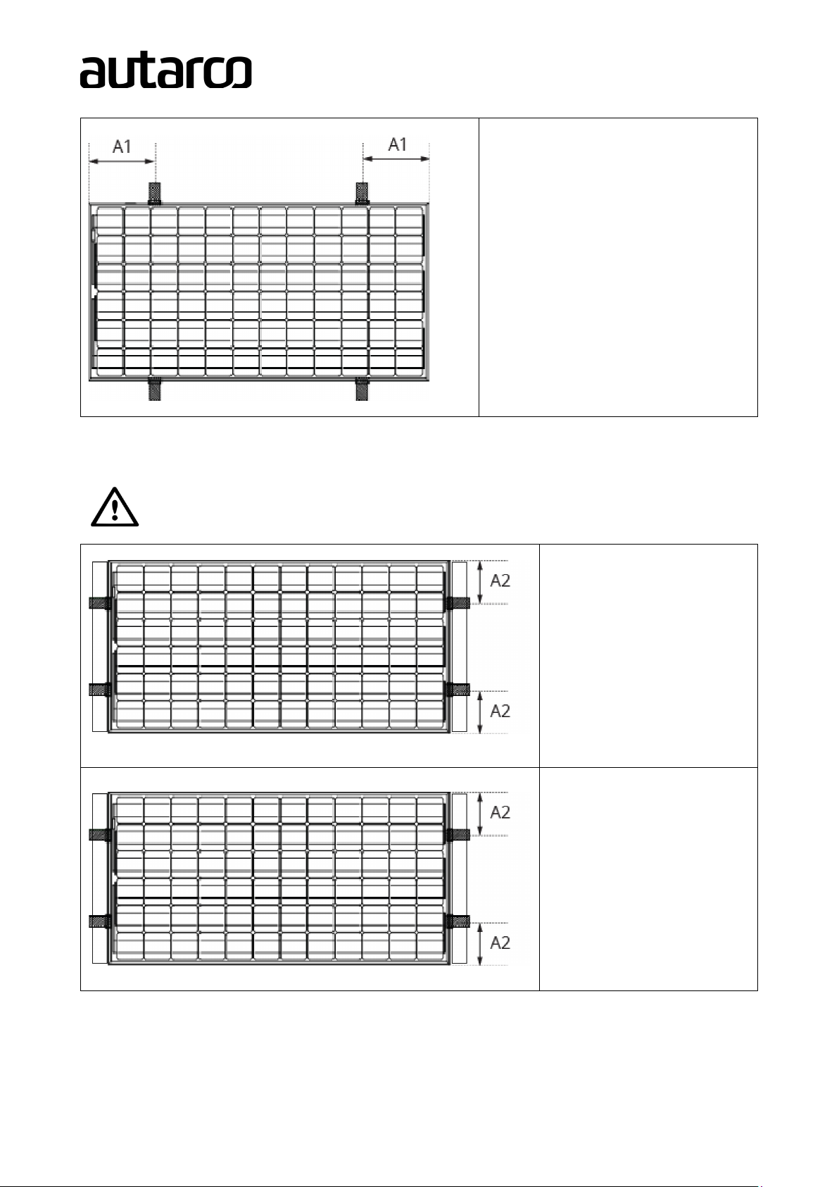
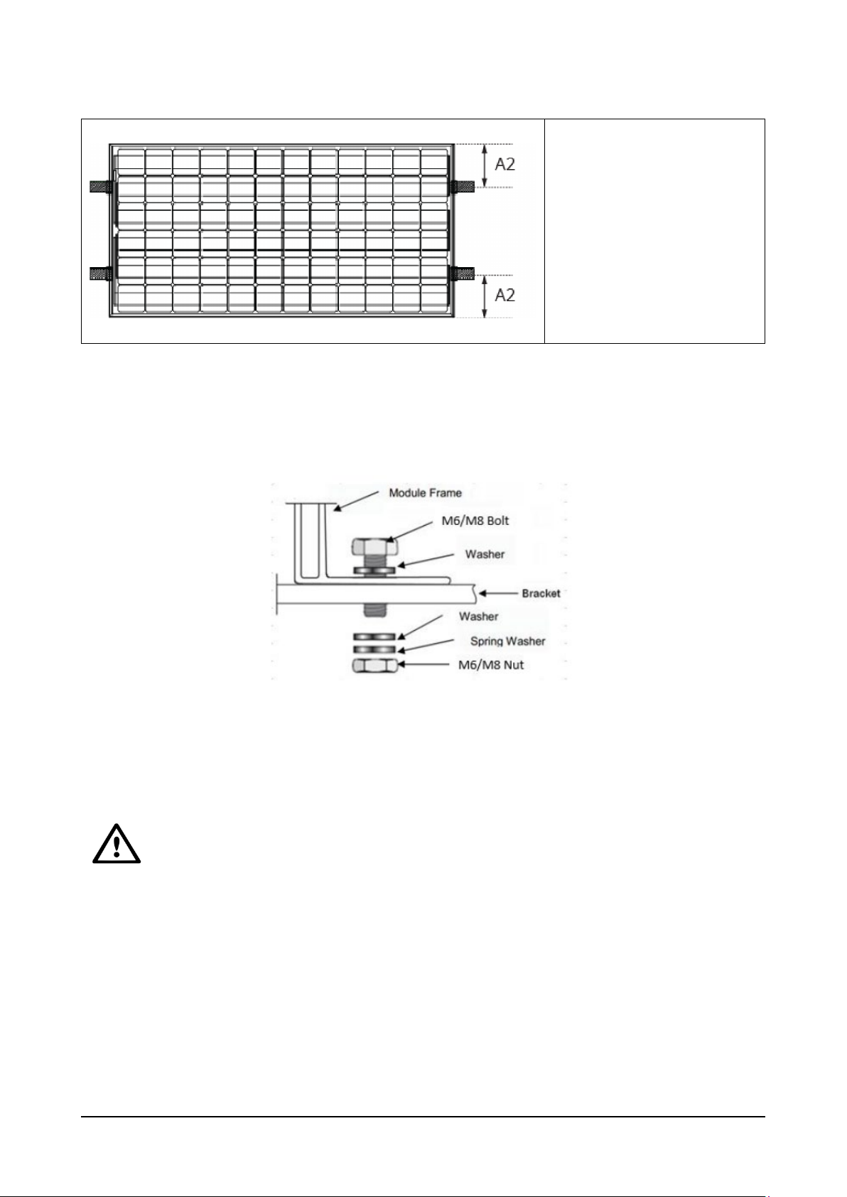
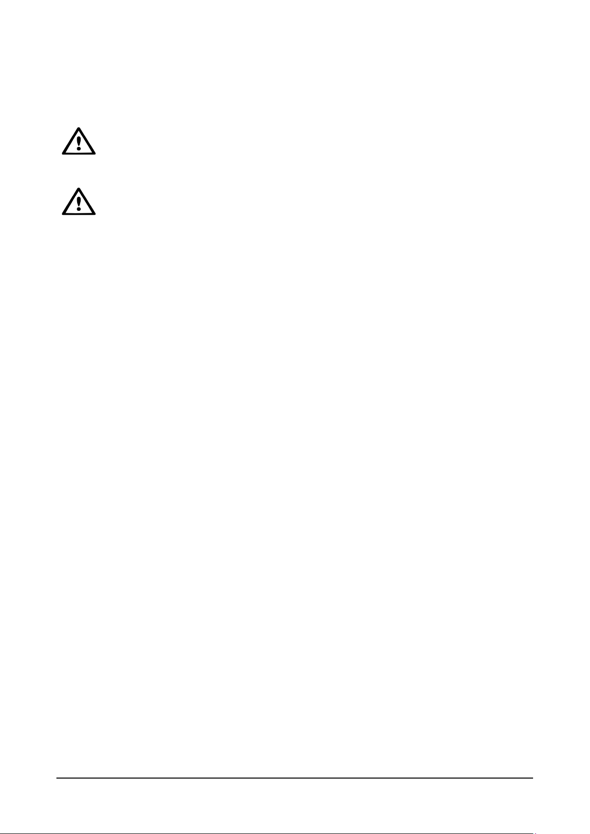
3.1 Keeping within the maximum permitted load
Make sure the support structure adheres to maximum permissible load requirements as prescribed by local ordinances,
particularly in regions of high snow accumulations and high wind velocities. Take notice of possible bending of the
modules under high loads. If possible, avoid installing fasteners, cable ties, etc. between the module backside and
support structure (i.e. on mounting rails) as any sharp edges can damage the module.
3.2 Grounding
The company installing the PV module frame is also responsible for proper grounding. If the building is already equipped
with an exterior lightning protection system, the PV-installation must be integrated in this protection system against
direct effects of lightning. Country specific standards must be adhered to. A grounding method authorized by UL is
mandatory in the US and Canada.
3.3 Fire safety
The roof construction and installation may affect the fire safety of a building; improper installation may contribute to
hazards in the event of a fire. For roof application, the modules should be mounted over a fire-resistant covering rated
for the application. The module is not Ex-proof that is, “non-explosion-protected equipment”. Hence it must not be
installed in the proximity of highly flammable gasses and vapors (e.g. filling stations, gas containers, paint spraying
equipment & other explosive environments). The module must not be installed near open flames or flammable
materials.
3.4 Suitable environmental conditions
The module is intended for use in temperate climatic conditions. The module must not be subjected to concentrated
light. It must not be immersed in water or constantly exposed to water spray (e.g. from fountains). It must not be
exposed to high concentrations of salt and sulfur (e.g. from sea or volcanos). The module may not be exposed to
extremely corrosive chemicals (e.g. emissions from manufacturing plants).
3.5 Suitable installation
Make sure the module meets the technical requirements of the system as a whole. Ensure that other system
components do not exert damaging mechanical or electrical influences on the modules. When connected in series, all
modules must have the same amperage. When connected in parallel, all modules must have the same voltage. The
modules must not be connected to create a voltage higher than the permitted system voltage. Modules must not be
fitted as overhead glazing or vertical glazing (façade). Ensure that the mounting system can also withstand the