Autarco Apex Minirail User manual

1 Apex Minirail mounting system
Installation Manual
Installation Manual IM-AMR-EN-V1.0
Apex Minirail
Mounting system
Portrait & landscape
orientation
DRAWN
CHK'D
APPV'D
MFG
Q.A
UNLESS OTHERWISE SPECIFIED:
DIMENSIONS ARE IN MILLIMETERS
SURFACE FINISH:
TOLERANCES:
LINEAR:
ANGULAR:
FINISH:
DEBURR AND
BREAK SHARP
EDGES
NAME
SIGNATURE
DATE
MATERIAL:
DO NOT SCALE DRAWING
REVISION
TITLE:
DWG NO.
SCALE:1:6.3
SHEET 1 OF 8
A0
SEE SPECIFIC PART DRAWINGS
WEIGHT: 204236.91
414-0011
MINI RAIL
MOUNTING WITH
CLICKNUT,
PORTRAIT
A A
B B
C C
D D
E E
F F
G G
H H
J J
K K
L L
M M
N N
P P
R R
T T
24
24
23
23
22
22
21
21
20
20
19
19
18
18
17
17
16
16
15
15
14
14
13
13
12
12
11
11
10
10
9
9
8
8
7
7
6
6
5
5
4
4
3
3
2
2
1
1

2Apex Minirail mounting system
Installation Manual

3Apex Minirail mounting system
Installation Manual
3IM-AMR-EN-V1.0
Information
Contact
www.autarco.com
Address
Torenallee 20
5617 BC Eindhoven
The Netherlands
This manual is an integral part of the unit. Please read the manual carefully
before installation, operation or maintenance. Keep this manual for future
reference.
Product information is subject to change without notice. All trademarks are
recognized as the property of their respective owners.
© Autarco Group B.V.
All rights reserved.
Installation Manual

4Apex Minirail mounting system
Installation Manual
Tables of contents
1
1.1
1.2
1.3
2
2.1
2.2
2.3
2.4
2.5
3
3.1
3.2
3.4
4
4.1
4.2
4.3
4.4
5
5
6
13
17
23
Introduction
Safety symbols
Target audience
Mounting rail models covered
Preparing for installation
Safety instructions
Package contents
Tools & materials required
Solar panel position guideline
Rails position guideline
Portrait installation
Marking the position of mounting rails
Mounting rails onto the roof
Attaching clamps onto the rails – Portrait orientation
Landscape installation
Marking the position of mounting rails
Mounting landscape rails on roof
Attaching clamps onto the rails
Mounting modules onto the clamps – Landscape orientation
Disposal

5Apex Minirail mounting system
Installation Manual
1
1.1
1.2
1.3
The main purpose of this installation manual is to provide instructions and detailed procedures
for installing and maintaining Autarco’ pitched trapezoidal roof mounting systems based on
minirails, for buildings up to 20m in height.
Safety symbols
DANGER! A danger symbol indicates a hazardous situation, which if not avoided, will result in
death or serious injury.
WARNING! Indicates a hazardous situation which, if not avoided, can result in serious injury.
ATTENTION! Attention statements are used to indicate where a part of the process or equipment
has a special requirement. Attention statements should be followed at all times.
Target audience
This manual is intended for qualified personnel only, who install an Autarco solar PV solution
with Minirail mounting systems. Before any further action, the installer must first read all safety
regulations and be aware of the potential danger to operate high-voltage devices such as PV
modules.
ATTENTION! Qualified personnel means a person with valid license from the local authority for:
- Installing electrical equipment and PV power systems (up to 1000 V)
- Applying all applicable installation codes and using personal protective equipment (PPE)
- Analyzing and reducing the hazards involved in performing electrical work
Mounting rail models covered
The Minirail is installed on corrugated (trapezoid) roofs using one of the following Autarco
mounting plates:
+ M2.AR6TRL395 – For Portrait mounting
+ M2.R5CRXL150 – For Landscape mounting
Further information on the types of roof mounting hooks are available online at
www.autarco.com/downloads/
Introduction
6Apex Minirail mounting system
Installation Manual
2
2.1 Safety instructions
DANGER! Do not install during severe or sub-zero weather conditions.
WARNING! Never step or sit on the glass surface of a solar module.
The glass may break, resulting in shock or bodily injury. The module may also stop generating
power.
WARNING! Always use the supplied parts to attach the solar modules and mounts.
Use of other parts is dangerous and may cause the solar modules or mounts to loosen or fall.
DANGER! Do not install this system on a roof with pitch > 60 degrees.
WARNING! The installation, maintenance, recycling, and disposal of the mounting components
must be performed by qualified personnel in compliance with national and local standards and
regulations.
WARNING! Always install modules onto a minimum of two rails which are parallel to the shorter
side of the module. Otherwise, loosening of the modules may occur due to expansion or
contraction of the rails under varying heat.
Any unauthorized actions including modification of product functionality of any form will affect the
validation of warranty service; Autarco may deny the obligation of warranty service accordingly.
Preparing for installation
7 Apex Minirail mounting system
Installation Manual
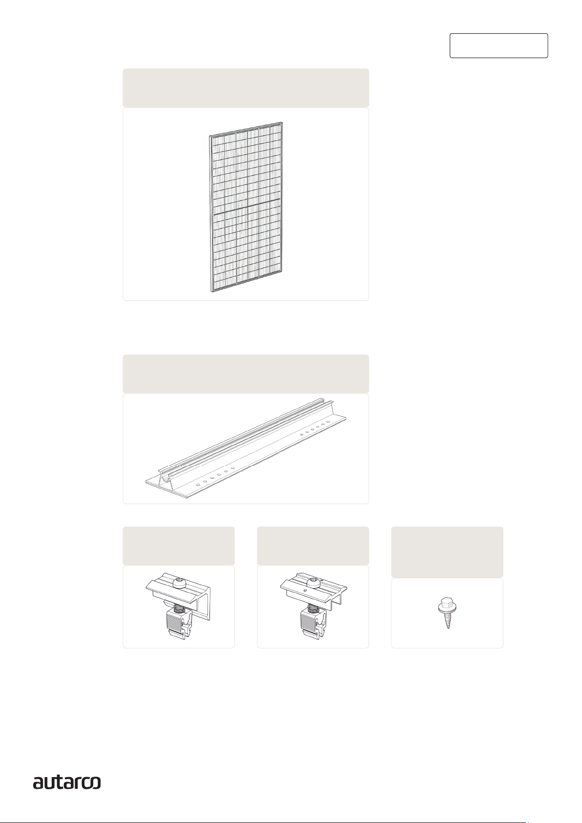
2.2 Package contents
Portrait mounting2.2.1
2a. End clamp
M1.AR6(B)EC
2. Minirail for portrait mounting
M2.AR6TRL395
2b. Middle clamp
M1.AR6(B)MC
1. Solar modules
S1.MHJ/TBJ/MHL/MHN
installation manual
Apex Minirail Mounting System 7
2.2. Package Contents
Solar Modules
S1.MHJ/TBJ/MHL/MHN
2.2.1 Portrait mounting
2 Minirail for portrait mounting
M2.AR6TRL395
2a End clamp 2b Middle Clamp 2c Mounting screw
M1.AR6
(
B
)
EC
M1.AR6
(
B
)
MC
M6.SCREW6X25-EPDMRING
1
2c. Mounting screw
M6.SCREW6X25-
EPDMRING
8 Apex Minirail mounting system
Installation Manual
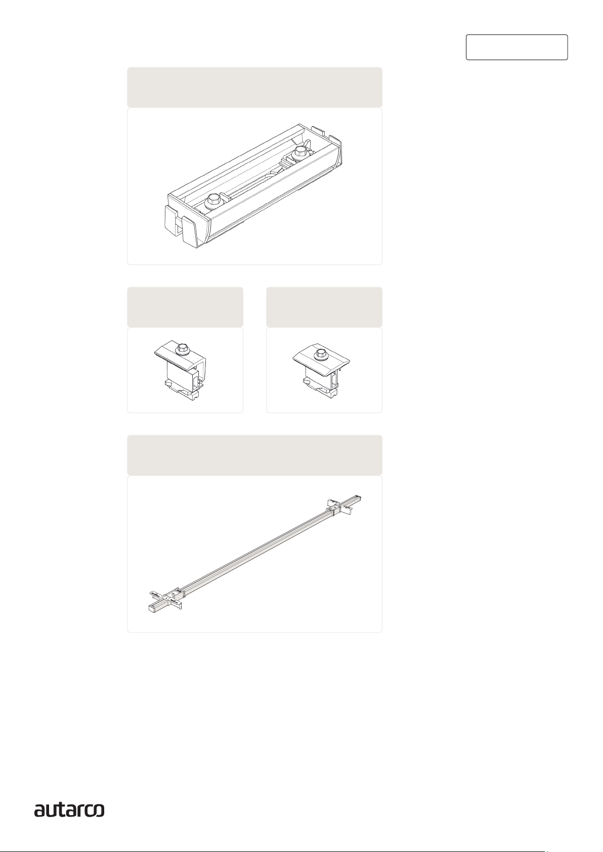
Landscape mounting2.2.2
3. Minirail for landscape mounting
M2.R5CRXL150 + M6.SCREW6X25-EPDMRING
3a. End clamp
M1.R5CRX(B)EC
3b. Middle clamp
M1.R5CRX(B)MC
4. Measuring tool
M3.CRXLMST-1400
Please note the component numberings as they will be referenced in the installation section.

9Apex Minirail mounting system
Installation Manual
2.3 Tools & materials required
A. Tape Measure
B.
installation manual
Apex Minirail Mounting System 9
D2
654
3
2
1
A Tape Measure
B
2.3. Tools & Materials Required
Electric Impact wrench with M8 bolt
C1
C1.
D2. Electric Impact wrench with M8 bolt
installation manual
Apex Minirail Mounting System 9
D2
654
3
2
1
A Tape Measure
B
2.3. Tools & Materials Required
Electric Impact wrench with M8 bolt
C1
installation manual
Apex Minirail Mounting System 9
D2
654
3
2
1
A Tape Measure
B
2.3. Tools & Materials Required
Electric Impact wrench with M8 bolt
C1
installation manual
Apex Minirail Mounting System 9
D2
6
54
3
2
1
A Tape Measure
B
2.3. Tools & Materials Required
Electric Impact wrench with M8 bolt
C1
10 Apex Minirail mounting system
Installation Manual
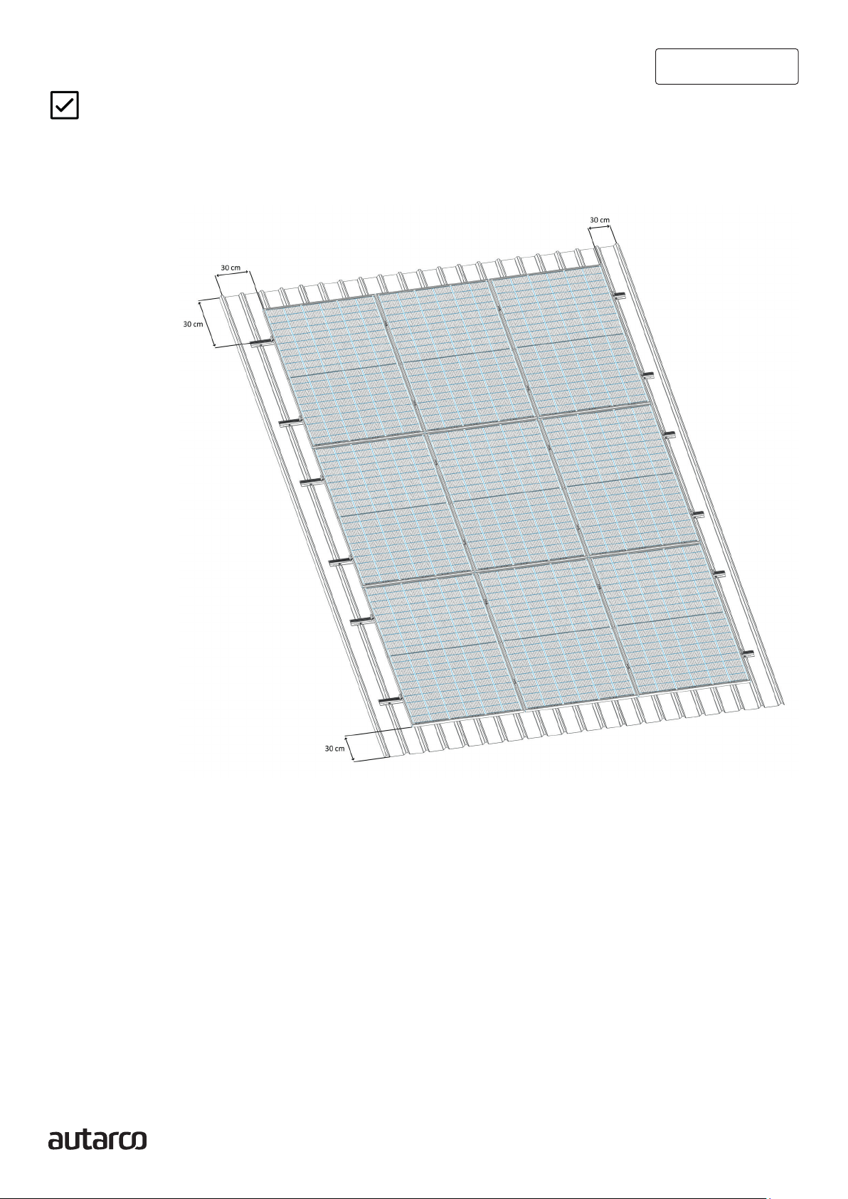
2.4 Solar panel position guideline
ATTENTION! DO NOT install this system on a roof with pitch > 60
degrees.
The minimum clearance of solar panels from the roof edges, gutters and ridges is typically 30cm
(please check with your local building regulations before proceeding).

11 Apex Minirail mounting system
Installation Manual
2.5
2.5.1
installation manual
Apex Minirail Mounting System 1
1
2.5. Rails Position Guideline
Before proceeding with the installation, make sure the rails are installed according to the dimensions given below:
Autarco Module Module Dimension (mm) Minimum Distance Maximum Distance
MHJ / TBJ / TJ Series 1722 1134 R1 0.52 x L 0.63 x L
MHL / TBL / TL Series 1903 1134 0.45 x L 0.66 x L
Table 1: Minimum and Maximum distance between rails for Autarco panels
The maximum distance between rails (R1) is depends on the length of the module (L) and is referenced in
Table 1. Refer to the ‘Mounting’ section of your module’s manual for module-specific values.
The maximum distance between two successive rails (R2) is 120cm, but typically 60-80cm.
The maximum rail overhang distance (OH) is 30cm.
The values for rail distance (R1) and overhang distance (OH) are determined by wind zone, height of the
building and terrain code.
2.5.1. Portrait Orientation
Rails position guideline
Before proceeding with the installation, make sure the rails are installed
according to the dimensions given below:
Autarco Module Module Dimension (mm) Minimum Distance Maximum Distance
MHJ / TBJ / TJ Series 1722 1134 R1 0.52 x L 0.63 x L
MHL / TBL / TL Series 1903 1134 R1 0.45 x L 0.66 x L
Table 1: Minimum and Maximum distance between rails for Autarco panels
- The maximum distance between rails (R1) is depends on the length of the module (L)
and is referenced in Table 1. Refer to the ‘Mounting’ section of your module’s manual for
module-specific values.
- The maximum distance between two successive rails (R2) is 120 cm, but typically 60-80
cm.
- The maximum rail overhang distance (OH) is 30 cm.
The values for rail distance (R1) and overhang distance (OH) are determined by wind zone, height
of the building and terrain code.
Portrait orientation

12 Apex Minirail mounting system
Landscape orientation2.5.2
ATTENTION! For larger installations, it is recommended to use several sizing tools.
Use the provided measuring tool, 4for positioning the rails accurately.
1. To adjust the sliding block, loosen the screw a few turns. Use a Philips screwdriver to do
this.
2. Place the sizing tool on the short size of a panel.
3. Slide the sliding blocks against the side of the panel and screw them in place.
Installation Manual
13 Apex Minirail mounting system
Installation Manual
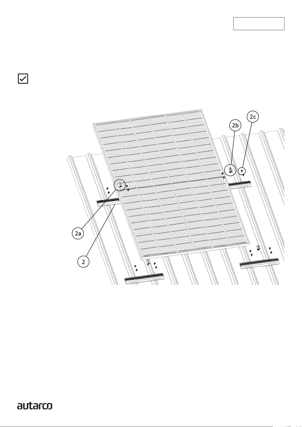
3Portrait installation
ATTENTION! Section 3 describes installation steps for Portrait Mounting only! Please skip to
Section 4, if your system will be mounted in Landscape orientation.
Exploded view, refer to Section 2.2.1 for component numberings.
An overview of the installation steps for the Minirail Portrait Mounting System in exact order:
3.1. Markingthepositionofmountingrails
3.2. Mounting rails onto the roof
3.3. Attachingclampsontotherails
3.4. Mountingmodulesontotheclamps

14 Apex Minirail mounting system
Installation Manual
3.1 Marking the position of
mounting rails
14 Apex Minirail Mounting System
3.1 Marking the position of mounting rails
Step 1 – Refer to Section 2.5 for the recommended rail (R1 & R2) distances.
Step 2 – Using a chalk or marker pen, mark points on the roof where the rails will be installed.
Using a chalk line, you may also mark the outer contours of the field.
1. Refer to Section 2.5 for the recommended rail (R1 & R2) distances.
2. Using a chalk or marker pen, mark points on the roof where the rails will be installed.
Using a chalk line, you may also mark the outer contours of the field.
3.2 Mounting portrait rails onto the roof
1. Align mounting profile to the points marked in 3.1.
2. Adjust the minirail to line up holes with the ridges of the roof sheet.
3. Add the necessary roofing screws to secure the minirail to the roof sheet.
4. Repeat steps 1 to 3, to install all profiles on the roof.
ATTENTION! DO not overtighten screws or bolts during installation (8 – 10 Nm).
installation manual
Apex Minirail Mounting System 1
5
3.2 Mounting Portrait rails onto the roof
Step 1 – Align mounting profile to the points marked in 3.1.
Step 2 – Adjust the minirail to line up holes with the ridges of the roof sheet.
Step 3 – Add the necessary roofing screws to secure the minirail to the roof sheet.
Step 4 – Repeat steps 1 to 3, to install all profiles on the roof.
ATTENTION! DO not overtighten screws or bolts during installation (8 – 10 Nm).

15 Apex Minirail mounting system
Installation Manual
3.3 Attaching clamps onto the rails
End clamps and mid clamps for portrait mounted minirail systems can
be easily screwed into the rails, using the steps given below. We use the
middle clamps for this illustration, but the steps remain the same for
end clamps.
1. Hinge both legs of the clamp into the rail.
2. Press firmly down to snap the hinged legs in place.
3. Slide the clamp into the desired position on the rail and screw bolt to fix position.
3.4
3.4.1
Mounting modules onto the rails
Portrait orientation
First module with end clamps
1. At either end of the installation, assemble two end clamps (see 3.3.1).
Ensure less than 30cm rail is protruding outwards of the end clamp (OH).
2. Position the solar module in portrait orientation on the rails and align against the end
clamps.
3. Tighten preassembled screws on the end clamps and fix the solar panel on to the rails.
installation manual
Apex Minirail Mounting System 1
3
3. Portrait Installation
ATTENTION! Section 3 describes installation steps for Portrait Mounting only!
Please skip to Section 4, if your system will be mounted in Landscape orientation.
Exploded view, refer to Section 2.2.1 for component numberings.
An overview of the installation steps for the Minirail Portrait Mounting System in exact order:
3.1. Marking the position of mounting rails
3.2. Mounting rails onto the roof
3.3. Attaching clamps onto the rails
3.4. Mounting modules onto the clamps

16 Apex Minirail mounting system
Installation Manual
3.4.2 Modules with middle clamps
4. Assemble middle clamps (see 3.3.1) onto the mounting profile
and slide left to align with the adjacent module.
NOTE! Do not tighten the clamps yet.
3.4.3 Final module with end clamps
9. Assemble two end clamps (see 3.3) onto the mounting profile and slide left to align with
the final module.
10. Tighten preassembled screws on the end clamps and fix the solar panel on to the rails.
Installation complete!
Repeat installation section 3.4 to complete remaining section of rows!
18 Minirail Mounting System
3.4.3 Final module with end clamps
Step 9 – Assemble two end clamps (see 3.3) onto the mounting profile and slide left to align with the
final module.
Step 10 – Tighten preassembled screws on the end clamps and fix the solar panel on to the rails
Installation complete!
Repeat installation section 3.4 to complete remaining section of rows!
5. Position the solar module in portrait orientation on the rails and align against the middle
clamps.
6. Connect the panel cables to the previous panel.
7. Tighten preassembled screws on the middle clamps and fix the solar panel on to the
rails.
8. Repeat steps 1 to 3 until the final solar module along the rails is installed.

17 Apex Minirail mounting system
Installation Manual
4Landscape installation
4.1
ATTENTION! Section 4 describes installation steps for Landscape Mounting only! Please go to
Section 3, if your system will be mounted in Portrait orientation.
An overview of the installation steps for the Minirail landscape mounting system in exact order:
4.1 Marking the position of mounting rails
4.2 Mounting Landscape rails onto the roof
4.3 Attaching clamps onto the rails
4.4 Mounting modules onto the clamps – Landscape orientation
Marking the position of mounting rails
1. Refer to Section 2.5 for the recommended rail (R1 & R2) distances.
2. Use a chalk or marker pen to mark the contours of the field.
3. Measure and identify position of the mounting rails using the provided tool.
Simultaneously, mark points on the roof where the rails will be installed.
18 Apex Minirail mounting system
Installation Manual
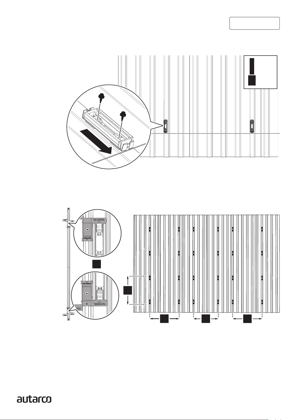
4.2 Mounting landscape rails on roof
1. Align the mounting profile to the points marked in 4.1.
2. Tighten the two preassembled screws of the mounting profile onto the roof.
3-4 Nm
5/16”
3. Repeat steps 1 and 2 to install the first horizontal row of mounting profiles.
4. Insert the sizing tool 4 into the cable clamp of the profile to be installed. Ensure the arrow
on the sizing tool points towards the mounting profile.
A
A
A
AA
5. Insert the sizing tool into the cable clamp of the installed mounting profile.
6. Screw on the next profile.

19 Apex Minirail mounting system
Installation Manual
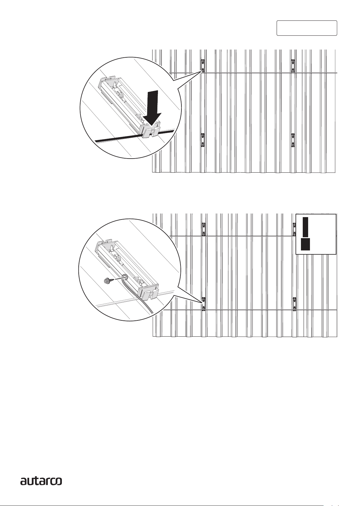
B
B
B
B
BB
7. Repeat steps 4 to 6 to install the remaining rows of mounting profiles.
ATTENTION! For installing the remaining mounting profiles, use the sizing tool in position B with
the STANDARD section.
Attaching clamps onto the rails
ATTENTION! All clamps for landscape system are inserted clockwise into the minirail and re-
moved counterclockwise.
End clamps and mid clamps for landscape mounted minirail systems can be easily snapped into
the rails, using the steps given below. We use the end clamps for this illustration, but the steps
remain the same for end clamps.
1
2
4.3
20 Apex Minirail mounting system
Installation Manual
- Place an end clamp in the first row of mounting profiles and
slide it to the end of the mounting profile against the stopper.
- You can clamp the return cable of the solar panels into the lower cable clamps! This
neatly conceals the return cable.
3-4 Nm
5/16”
- Optional! Install the earthing cables to the lower mounting profiles with a self-driving
screw.
Table of contents
Other Autarco Solar Panel manuals


Popular Solar Panel manuals by other brands


Qcells
Qcells Q.MAXX-G4 Series Installation and operation manual

Qcells
Qcells Q.MAXX-G3 Series Installation and operation manual

CanadianSolar
CanadianSolar CS Series installation manual

Num'axes
Num'axes NGPIEACC033 user guide

Qcells
Qcells Q.PRO-G4.X Nstallation and operations manual

Sun Power
Sun Power SPR-315E-WHT-D Safety and installation instructions


