AUTEC Air series User manual

Original instructions
AIR SERIES
Part D: receiving unit
ACRM5E (RMH)
INDEX
1 Description ............................................................................................................ 2
2 Technical data ....................................................................................................... 3
3 Technical data sheet ............................................................................................. 4
4 Plates ..................................................................................................................... 4
4.1 Plates on ACRM5E unit in a radio remote control ............................................ 4
4.2 Plates on ACRM5E unit in a Take & Release radio remote control ................... 4
4.3 Plates on ACRM5E unit in a Multi Units or Multi Receiver radio remote control 5
5 Light signals .......................................................................................................... 5
5.1 POWER LED (green) ....................................................................................... 5
5.2 ENABLE LED (green) ...................................................................................... 5
6 Operation ............................................................................................................... 6
6.1 Electronic module ............................................................................................ 6
6.2 DIP switches .................................................................................................... 6
6.3 Internal light signals ......................................................................................... 6
6.4 Command outputs ............................................................................................ 6
7 Malfunction signalled by the receiving unit ........................................................ 7
AUTEC LIRMHE00-00
2
LIRMHE00-00
Description
AUTEC - Air series
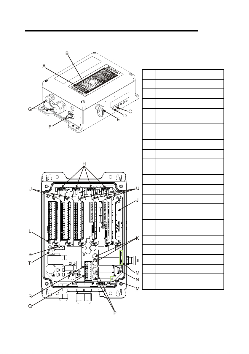
1 Description
AIdentication plate
BTechnical data plate
CENABLE LED
DPOWER LED
EConnector for cable control
(optional)
FBNC connector for external
antenna kit (optional)
GCable gland or plug
HDigital inputs
JElectronic module and address
key
KSTOP contacts protection fuses
LDIP switches
MInternal light signals
NConnector for the cable
control's wiring
PSAFETY contacts protection
fuses
QSAFETY outputs
RSTOP outputs
SConnector for power supply
TPower supply protection fuse
UOptional card (with related
command outputs)

AUTEC - Air series
Technical data 3
LIRMHE00-00
2 Technical data
Power supply ............................................................................................. 24-240V (1A)
Power supply protection fuse ............................................................ 2A T 250V (5x20mm)
Digital inputs voltage .................................................................................... 24/48/110V
............................................................................................................................ 12/24V
Antenna ............................................................................................. internal or dedicated
STOP contacts rated current ......................................................................... 6A (250V )
STOP contacts protection fuses ....................................................... 6A T 250V (5x20mm)
SAFETY contacts rated current ................................................................... 10A (250V )
SAFETY contacts protection fuses ................................................. 10A T 250V (5x20mm)
Housing material .......................................................................................... PA 6 (20%fg)
Protection degree ....................................................................................... IP65 (NEMA 4)
Weight ........................................................................................................... 2.2kg (4.9Lb)
Command outputs are provided on the optional cards. Refer to technical data sheet for voltage
and current rating of command outputs.
4
LIRMHE00-00
Technical data sheet
AUTEC - Air series
3 Technical data sheet
The technical data sheet contains the wiring diagram showing the connection between the
receiving unit and the machine. It also contains the transmitting unit conguration and shows
the matching between commands sent and machine functions/movements.
Each technical data sheet must be lled in, checked and signed by the installer, who is
responsible for a correct wiring.
A technical data sheet must always be kept toghether with this manual (always keep a copy
of the technical data sheet when it is used for administrative purposes).
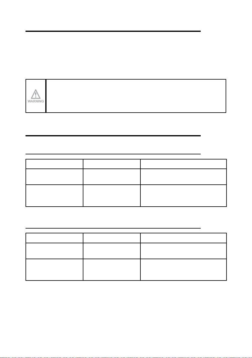
The wiring of the receiving unit outputs must always reect the wiring
indicated in the technical data sheet.
4 Plates
4.1 Plates on ACRM5E unit in a radio remote control
Plate Position Content
radio remote control
identication plate
On the cover of the
receiving unit.
Radio remote control serial number
(S/N), bar code and manufacturing year.
technical data plate On the cover of the
receiving unit.
MODEL, TYPE and main receiving unit
technical data, marking and possible
radio remote control marks.
4.2 Plates on ACRM5E unit in a Take & Release radio remote control
Plate Position Content
radio remote control
identication plate
On the cover of the
receiving unit.
Radio remote control serial number
(S/N), bar code and manufacturing year.
technical data plate On the cover of the
receiving unit.
MODEL, TYPE and main receiving unit
technical data, marking and possible
radio remote control marks.
AUTEC - Air series
Light signals 5
LIRMHE00-00
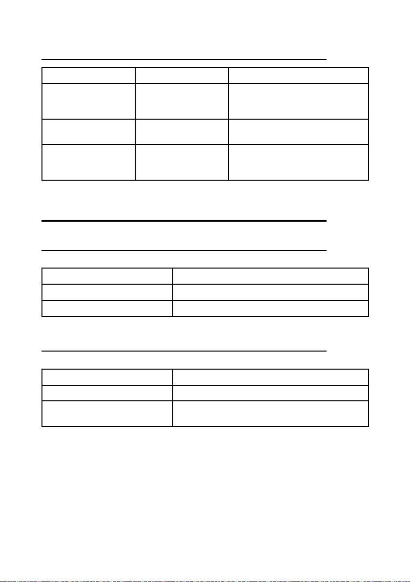
4.3 Plates on ACRM5E unit in a Multi Units or Multi Receiver radio remote
control
Plate Position Content
radio remote control
identication plate
On the cover of each
receiving unit.
Radio remote control serial number
(MULTI S/N), bar code and
manufacturing year.
receiving unit
identication plate
On the cover of each
receiving unit.
The serial number of the receiving unit
(S/N) and a bar code.
technical data plate On the cover of each
receiving unit.
MODEL, TYPE and main receiving unit
technical data, marking and possible
radio remote control marks.
5 Light signals
5.1 POWER LED (green)
The POWER LED indicates the status of the receiving unit.
The POWER LED... Meaning
…is o The receiving unit is not powered.
...is on Receiving unit is powered.
5.2 ENABLE LED (green)
The ENABLE LED indicates the status of the radio link.
The ENABLE LED … Meaning
… blinks once every 5 seconds The receiving and transmitting unit do not communicate.
… blinks fast The unit is ready to receive commands sent by the
transmitting unit.

6
LIRMHE00-00
Operation
AUTEC - Air series
6 Operation
6.1 Electronic module
The electronic module contains the address key, where the radio remote control conguration
data are also stored. The receiving unit cannot work without this address key.
6.2 DIP switches
DIP switch 1 is used to set the frequency band.
DIP switch 2 shall always be set in the OFF position: do not modify it.
6.3 Internal light signals
The activation of each relay on the mother board is signalled by an LED near the relay.
6.4 Command outputs
The data sheet contains information regarding the correspondence between the commands
sent by the transmitting unit and the related output enabled in the receiving unit.

AUTEC - Air series
Malfunction signalled by the receiving unit 7
LIRMHE00-00
7 Malfunction signalled by the receiving unit
Use the light signals on the receiving unit to identify the radio remote control malfunction.
If the problem persists after the suggested solution has been carried out, contact the support
service of the machine manufacturer.
Signals Possible reason Solutions
The POWER LED is o. Wrong or no power
supply.
Correctly plug in the connecting plug
between the radio remote control and
the machine.
Make sure that power supply wires are
correctly connected and that the power
supply value is within the limits specied
in the technical data.
Check the power supply protection fuse
and, if needed, replace it.
The POWER LED is
steady and the ENABLE
LED blinks once every 5
seconds.
The transmitting and
receiving unit do not
communicate.
Start up the radio remote control.
The POWER LED is
steady and the ENABLE
LED blinks fast.
The receiving unit does
not activate the outputs of
the commands sent.
Check that the outputs are correctly
wired and that the commands sent
activate the corresponding relays.
Check the protection fuses of the STOP
contacts or of the SAFETY contacts and,
if needed, replace them.

Other manuals for Air series
15
This manual suits for next models
1
Table of contents
Other AUTEC Receiver manuals


 operating instructions")


