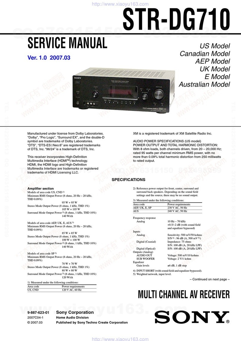
Sony HD-X1 User manual

SERVICE MANUAL
AUDIO POWER SPECIFICATIONS
POWER OUTPUT AND
TOTAL HARMONIC
DISTORTION: With 6 ohm loads, both
channels driven, from
200 – 20,000 Hz; rated
20 W per channel
minimum RMS power,
with no more than 0.7 %
total harmonic distortion
from 250 milli watts to
rated output.
Amplifier section
Front Poweroutput(rated):40W
+ 40 W (6 ohms, 1 kHz,
THD 1 %)
Continuous RMS power
output (reference): 50 W +
50 W (6 ohms at 1 kHz,
THD 10 %)
Front surround Poweroutput (rated): 40 W
+ 40 W (6 ohms, 1 kHz,
THD 1 %)
Subwoofer Poweroutput (rated):40W
+ 40 W (6 ohms, 100 Hz,
THD 1 %)
Continuous RMS power
output (reference): 50 W +
50 W (6 ohms at 100 Hz,
THD 10 %)
* Depending on the sound field settings and the source,
there may be no sound output.
Inputs (Analogue)
VIDEO 1/SAT 1, VIDEO 2/SAT 2
Sensitivity: 250/450 mV
RMS
Impedance: 50 kilohms
TV Sensitivity: 450 mV RMS
Impedance: 50 kilohms
Continuous RMS power
output (reference): 50 W +
50 W (6 ohms at 1 kHz,
THD 10 %)
(US model only)
Inputs (Digital)
VIDEO 1/SAT 1, VIDEO 2/SAT 2, TV
Impedance: 75 ohms
Super Audio CD/DVD system
Laser Semiconductor laser
NTSC/PAL
except US, Canadian models:
US, Canadian models: NTSC
(DVD: λ= 650 nm)
(CD: λ= 790 nm)
Emission duration:
continuous
Signal format system
SUPER AUDIO CD/DVD RECEIVER
US Model
Canadian Model
AEP Model
UK Model
E Model
HCD-X1
Ver. 1.2 2005.12
SPECIFICATIONS
9-879-627-03
2005L05-1
© 2005.12
Sony Corporation
Home Audio Division
Published by Sony Engineering Corporation
– Continued on next page –
HCD-X1istheamplifier, super audio CD/DVDsystem,
tuner and video section in DAV-X1.
This product incorporates copyright protection
technology that is protected by U.S. patents and
other intellectual property rights. Use of this
copyright protection technology must be
authorized by Macrovision, and is intended for
home and other limited viewing uses only unless
otherwise authorized by Macrovision. Reverse
engineering or disassembly is prohibited.
This system incorporates with Dolby*
1
Digital
and Dolby Pro Logic (II) adaptive matrix
surround decoder and the DTS*
2
Digital
Surround System.
This system perfectly decodes 5.1 channel
signal, but you cannot add other commercially
available surround speakers.
*1 Manufactured under license from Dolby
Laboratories.
“Dolby,” “Pro Logic,” and the double-D symbol are
trademarks of Dolby Laboratories.
*2 Manufactured under license from Digital Theater
Systems, Inc.
“DTS” and “DTS Digital Surround” are trademarks
of Digital Theater Systems, Inc.
Model Name Using Similar Mechanism NEW
DVD Mechanism Type CDM85-DVBU102
Optical Pick-up Block Name KHM-310CAA

2
HCD-X1
ATTENTION AU COMPOSANT AYANT RAPPORT
À LA SÉCURITÉ!
LES COMPOSANTS IDENTIFIÉS PAR UNE MARQUE 0SUR
LES DIAGRAMMES SCHÉMATIQUES ET LA LISTE DES
PIÈCES SONT CRITIQUES POUR LA SÉCURITÉ DE
FONCTIONNEMENT. NE REMPLACER CES COM- POSANTS
QUE PAR DES PIÈCES SONY DONT LES NUMÉROS SONT
DONNÉS DANS CE MANUEL OU DANS LES SUPPLÉMENTS
PUBLIÉS PAR SONY.
SAFETY-RELATED COMPONENT WARNING!!
COMPONENTS IDENTIFIED BY MARK 0 OR DOTTED LINE
WITH MARK 0ON THE SCHEMATIC DIAGRAMS AND IN
THE PARTS LIST ARE CRITICAL TO SAFE OPERATION.
REPLACE THESE COMPONENTS WITH SONY PARTS WHOSE
PART NUMBERS APPEAR AS SHOWN IN THIS MANUAL OR
IN SUPPLEMENTS PUBLISHED BY SONY.
Notes on chip component replacement
•Never reuse a disconnected chip component.
•Notice that the minus side of a tantalum capacitor may be
damaged by heat.
Flexible Circuit Board Repairing
•Keep the temperature of the soldering iron around 270 ˚C
during repairing.
•Do not touch the soldering iron on the same conductor of the
circuit board (within 3 times).
•Be careful not to apply force on the conductor when soldering
or unsoldering.
CAUTION
Use of controls or adjustments or performance of procedures
otherthanthosespecifiedherein may result in hazardous radiation
exposure.
SAFETY CHECK-OUT
After correcting the original service problem, perform the following
safety check before releasing the set to the customer:
Check the antenna terminals, metaltrim, “metallized” knobs, screws,
and all other exposed metal parts forAC leakage.
Check leakage as described below.
LEAKAGE TEST
The AC leakage from any exposed metal part to earth ground and
from all exposed metal parts to any exposed metal part having a
return to chassis, must not exceed 0.5 mA (500 microamperes.).
Leakage current can be measured by any one of three methods.
1. A commercial leakage tester, such as the Simpson 229 or RCA
WT-540A. Follow the manufacturers’instructions to use these
instruments.
2. A battery-operatedAC milliammeter. The Data Precision 245
digital multimeter is suitable for this job.
3. Measuring the voltage drop across a resistor by means of a
VOMor battery-operatedACvoltmeter.The “limit” indication
is 0.75V, so analog meters must have an accurate low-voltage
scale. The Simpson 250 and Sanwa SH-63Trd are examples
of a passiveVOM that is suitable. Nearly all battery operated
digital multimeters that have a 2VAC range are suitable. (See
Fig. A)
Fig. A. Using an AC voltmeter to check AC leakage.
1.5 k
Ω
0.15
µ
FAC
voltmete
r
(0.75 V)
To Exposed Metal
Parts on Set
Earth Ground
This appliance is classified as
a CLASS 1 LASER product.
The CLASS 1 LASER
PRODUCT MARKING is
located on the bottom of the unit.
Tuner section
System PLL quartz-locked digital
synthesizer system
FM tuner section
Tuning range 87.5 – 108.0 MHz
US, Canadian models:
(100 kHz step)
except US, Canadian
models: (50 kHz step)
US, Canadian models: 530 – 1,710 kHz (with the
Antenna (aerial) FM wire antenna (aerial)
Antenna (aerial) terminals 75 ohms, unbalanced
Intermediate frequency 10.7 MHz
AM tuner section
Tuning range
interval set at 10 kHz)
531 – 1,710 kHz (with the
interval set at 9 kHz)
AEP, UK, Russian models:531 – 1,602 kHz (with the
interval set at 9 kHz)
Singapore model: 531 – 1,602 kHz (9 kHz)
530 – 1,710 (10 kHz)
Antenna (aerial) AM loop antenna (aerial)
Intermediate frequency 450 kHz
Video section
Outputs Video: 1 Vp-p 75 ohms
S video:
Y: 1 Vp-p 75 ohms
C: 0.286 Vp-p 75 ohms
COMPONENT:
Y: 1 Vp-p 75 ohms
P
B
/C
B
, P
R
/C
R
: 0.7 Vp-p
75 ohms
Input VIDEO: 1 Vp-p 75 ohms
S video:
Y: 1 Vp-p 75 ohms
C: 0.286 Vp-p 75 ohms
General
Power requirements
US, Canadian models: 120 V AC, 60 Hz
except US, Canadian models:
220 – 240 V AC, 50/60 Hz
Power consumption On: 85 W
Standby: 0.3 W (at the
Power Saving Mode)
Dimensions (approx.) 380 ×76 ×293 mm
(15 ×3 ×11
5
/8inches) (w/
h/d) incl. projecting parts
Mass (approx.)
US, Canadian models: 4.6 kg (10 lb 3 oz)
except US, Canadian models:
4.5 kg
Design and specifications are subject to change
without notice.

3
HCD-X1
•Theinstructions in this manual describe the
controls on the remote. You can also use the
controls on the system if theyhave the same or
similar names as those on the remote.
•The Control Menu items may be different
depending on the area.
•“DVD” may be used as a general term for
DVD VIDEOs, DVD+RWs/DVD+Rs, and
DVD-RWs/DVD-Rs.
•Measurements are expressed in feet (ft) for
North American models.
•Thefollowing symbols are used in this
manual.
*MP3 (MPEG1 Audio Layer 3) is a standard format
defined by ISO/MPEG which compresses audio
data.
The “DVD VIDEO” logo and “DVD-RW” logo are
trademarks.
*1Except for multi-channel playback area.
*2CD text data can be displayed (album title only).
Note about CDs/DVDs
The system can play CD-ROMs/CD-Rs/CD-
RWs recorded in the following formats:
–audioCDformat
–videoCDformat
About This Manual
Symbol Meaning
Functions available for DVD
VIDEOs, DVD-Rs/DVD-RWs in
video mode, and DVD+Rs/
DVD+RWs
Functions available for DVD-RWs
in VR (Video Recording) mode
Functions available for VIDEO
CDs (including Super VCDs or CD-
Rs/CD-RWs in video CD format or
Super VCD format)
FunctionsavailableforSuperAudio
CDs
Functions available for music CDs
or CD-Rs/CD-RWs in music CD
format
Functions available for DATA CDs
(CD-ROMs/CD-Rs/CD-RWs
containing MP3* audio tracks and
JPEG image files)
This System Can Play the
Following Discs
Format of
discs Disc logo
DVD VIDEO
DVD-RW
VIDEO CD
Super Audio
CD*1
Audio CD*2
CD-R/CD-RW
(audio data)
(MP3 files)
(JPEG files)
–MP3audiotracks, JPEG image files, and
DivXvideo files of format conforming to ISO
9660 Level 1/Level 2, or its extended format,
Joliet
The system can play DVD-ROMs/DVD+RWs/
DVD-RWs/DVD+Rs/DVD-Rs recorded in the
following formats:
–DivXvideofiles of format conforming to
UDF.
Example of discs that the
system cannot play
The system cannot play the following discs:
•CD-ROMs recorded in PHOTO CD format
•Datapart of CD-Extras
•DVD Audios
•DVD-RAMs
•ADVD VIDEO with a different region code.
•Adiscthat has a non-standard shape (e.g., card
shaped, heart shaped).
•Adiscthathas a commercially available
accessory attached, such as a label or ring.
•Anadaptertoconvert an 8 cm disc to standard
size.
•Adisc with paper or stickers on it.
•Adiscthathas the adhesive of cellophane tape
or a sticker still left on it.
Notes about CD-R/CD-RW/DVD-R/
DVD-RW/DVD+R/DVD+RW
In some cases, CD-R/CD-RW/DVD-R/DVD-RW/
DVD+R/DVD+RW cannot be played on this system
due to the recording quality or physical condition of the
disc, or the characteristics of the recording device and
authoring software.
The disc will not play if it has not been correctly
finalized. For more information, see the operating
instructions for the recording device.
Note that discs created in the Packet Write format
cannot be played.
Music discs encoded with
copyright protection
technologies
This product is designed to play back discs that
conform to the Compact Disc (CD) standard.
Recently, various music discs encoded with copyright
protection technologies are marketed by some record
companies. Please be aware that among those discs,
there aresome thatdo not conform to the CD standard
and may not be playable by this product.
Note on DualDisc
A DualDisc is a two sided disc product which mates
DVD recorded material on one side with digital audio
material on the other side. However, since the audio
material side does not conform to the Compact Disc
(CD) standard, playback on this product is not
guaranteed.
Note about DVD-RW (Except for
U.S./Canadian/European models)
Images in DVD-RWs with CPRM
*protection may not
be played if they contain a copy protection signal.
“Copyright lock” appears on the screen.
*CPRM (Content Protection for Recordable Media) is
a coding technology that protects the copyright of
images.
Label
Ring
Adapter

4
HCD-X1
Note on PBC (Playback
Control) (VIDEO CDs)
Thissystem conforms to Ver. 1.1 and Ver. 2.0 of
VIDEO CD standards. You can enjoy two kinds
of playback depending on the disc type.
Disc type You can
VIDEO CDs
without PBC
functions
(Ver. 1.1 discs)
Enjoy video playback (moving
pictures) as well as music.
VIDEO CDs
with PBC
functions
(Ver. 2.0 discs)
Play interactive software using
menu screens displayed on the
TV screen (PBC Playback), in
addition to the video playback
functions of Ver. 1.1 discs.
Moreover, you can play high-
resolution still pictures, if they
are included on the disc.
About Multi Session CD
•This system can play Multi Session CDs when
an MP3 audio track is contained in the first
session. Any subsequent MP3 audio tracks
recorded in later sessions can also be played
back.
•This system can play Multi Session CDs when
a JPEG image file is contained in the first
session. Any subsequent JPEG image files
recorded in later sessions can also be played
back.
•If audio tracks and images in music CD format
or video CD format are recorded in the first
session, only the first session will be played
back.
About the Super Audio CD
Super Audio CD is a new high-quality audio
disc standard where music is recorded in the
DSD (Direct Stream Digital) format
(conventional CDs are recorded in the PCM
format). The DSD format, using a sampling
frequency 64 times higher than that of a
conventional CD, and with 1-bit quantization,
achieves both a wide frequency range and a wide
dynamic range across the audible frequency
range, and so provides music reproduction
extremely faithful to the original sound.
Types of Super Audio CDs
There are two types of discs, depending on the
Super Audio CD layer and CD layer
combination.
•
•
Super Audio CD layer: A high-density
signal layer for Super Audio CD
CD layer*
1
: A layer that is readable by a
conventional CD player
*1You can play the CD layer on a conventional CD
player.
*2Since both layers are on one side, it is not necessary
to turn the disc over.
*3To select a layer, see “Selecting a Playback layer for
a Super Audio CD”.
Region code
Your system has a region code printed on the
back of theunitand will onlyplayDVDslabeled
with the same region code.
DVD VIDEOs labeled will also play on this
system.
If you try to play any other DVD VIDEO, the
message [Playback prohibited by area
limitations.] will appear on the TV screen.
Depending on theDVD VIDEO, no region code
indication may be giveneventhoughplayingthe
DVD VIDEO is prohibited by area restrictions.
Note on playback operations
of DVDs and VIDEO CDs
Someplayback operationsof DVDs andVIDEO
CDs may be intentionally set by software
producers. Since this system plays DVDs and
VIDEO CDs according to the disc contents the
software producers designed, some playback
features may not be available. Also, refer to the
instructions supplied with the DVDs or VIDEO
CDs.
Single layer disc
(a disc with a single Super Audio CD layer)
Super Audio CD
layer
Hybrid disc*
2
(a disc with an Super Audio CDlayer and a CDlayer)
Super Audio CD
layer*
3
CD layer*
3
ALL

5
HCD-X1
TABLE OF CONTENTS
1. SERVICING NOTES ............................................... 6
2. GENERAL ................................................................... 10
3. DISASSEMBLY
3-1. Disassembly Flow ........................................................... 12
3-2. Optical Pick-up Block (KHM-310CAA) ........................ 12
3-3. Side Panel (L/R) .............................................................. 13
3-4. Case (AL) ........................................................................ 13
3-5. Front Panel Section ......................................................... 14
3-6. MAIN Board.................................................................... 15
3-7. D.C. Fan (M450), Back Panel Section ............................ 15
3-8. DVD Mechanism Deck (CDM85-DVBU102) ................ 16
3-9. Chuck Cam, Belt ............................................................. 17
4. TEST MODE.............................................................. 18
5. ELECTRICAL ADJUSTMENTS ......................... 21
6. DIAGRAMS
6-1. Block Diagram – RF SERVO/VIDEO Section – ............ 22
6-2. Block Diagram
– HDMI Section (US and Canadian models) – ............... 23
6-3. Block Diagram – MAIN Section –.................................. 24
6-4. Block Diagram – AMP Section – .................................... 25
6-5. Block Diagram
– PANEL/POWER SUPPLY Section – ........................... 26
6-6. Printed Wiring Boards – DMB10 Section (1/2) – ........... 28
6-7. Printed Wiring Board – DMB10 Section (2/2) –............. 29
6-8. Schematic Diagram – DMB10 Section (1/4) – ............... 30
6-9. Schematic Diagram – DMB10 Section (2/4) – ............... 31
6-10. Schematic Diagram – DMB10 Section (3/4) – ............... 32
6-11. Schematic Diagram – DMB10 Section (4/4) – ............... 33
6-12. Printed Wiring Board – MIB01 Board (Component Side)
(US and Canadian models) –........................................... 34
6-13. Printed Wiring Board – MIB01 Board (Conductor Side)
(US and Canadian models) –........................................... 35
6-14. Schematic Diagram
– MIB01 Board (1/5) (US and Canadian models) –........ 36
6-15. Schematic Diagram
– MIB01 Board (2/5) (US and Canadian models) –........ 37
6-16. Schematic Diagram
– MIB01 Board (3/5) (US and Canadian models) –........ 38
6-17. Schematic Diagram
– MIB01 Board (4/5) (US and Canadian models) –........ 39
6-18. Schematic Diagram
– MIB01 Board (5/5) (US and Canadian models) –........ 40
6-19. Schematic Diagram – IO Board – ................................... 41
6-20. Printed Wiring Board
– IO Board (Component Side) –...................................... 42
6-21. Printed Wiring Board
– IO Board (Conductor Side) – ....................................... 43
6-22. Printed Wiring Board
– SCART Board (AEP, UK and Russian models) – ........ 44
6-23. Schematic Diagram
– SCART Board (AEP, UK and Russian models) – ........ 45
6-24. Printed Wiring Board
– MAIN Board (Component Side) – ............................... 46
6-25. Printed Wiring Board
– MAIN Board (Conductor Side) – ................................. 47
6-26. Schematic Diagram – MAIN Board (1/4) – .................... 48
6-27. Schematic Diagram – MAIN Board (2/4) – .................... 49
6-28. Schematic Diagram – MAIN Board (3/4) – .................... 50
6-29. Schematic Diagram – MAIN Board (4/4) – .................... 51
6-30. Printed Wiring Board – SWITCH Board – ..................... 52
6-31. Schematic Diagram – SWITCH Board – ........................ 53
6-32. Printed Wiring Board – FL Board – ................................ 54
6-33. Schematic Diagram – FL Board – ................................... 55
6-34. Printed Wiring Board
– POWER-AMP Board (Component Side) – .................. 56
6-35. Printed Wiring Board
– POWER-AMP Board (Conductor Side) –.................... 57
6-36. Schematic Diagram – POWER-AMP Board (1/3) – ....... 58
6-37. Schematic Diagram – POWER-AMP Board (2/3) – ....... 59
6-38. Schematic Diagram – POWER-AMP Board (3/3) – ....... 60
7. EXPLODED VIEWS
7-1. Case (AL), Side Panel Section ........................................ 90
7-2. Front Panel Section ......................................................... 91
7-3. MAIN Board Section....................................................... 92
7-4. POWER-AMP Board Section ......................................... 93
7-5. Chassis Section................................................................ 94
7-6. DVD Mechanism Deck Section (CDM85-DVBU102) ... 95
8. ELECTRICAL PARTS LIST................................ 96

6
HCD-X1 SECTION 1
SERVICING NOTES
NOTES ON HANDLING THE OPTICAL PICK-UP
BLOCK OR BASE UNIT
The laser diode in the optical pick-up block may suffer electrostatic
break-down because of the potential difference generated by the
charged electrostatic load, etc. on clothing and the human body.
During repair, pay attention to electrostatic break-down and also
use the procedure in the printed matter which is included in the
repair parts.
The flexible board is easily damaged and should be handled with
care.
NOTES ON LASER DIODE EMISSION CHECK
The laser beam on this model is concentrated so as to be focused on
the disc reflective surface by the objective lens in the optical pick-
up block. Therefore, when checking the laser diode emission,
observe from more than 30 cm away from the objective lens.
UNLEADED SOLDER
Boards requiring use of unleaded solder are printed with the lead-
free mark (LF) indicating the solder contains no lead.
(Caution: Some printed circuit boards may not come printed with
the lead free mark due to their particular size)
: LEAD FREE MARK
Unleaded solder has the following characteristics.
•Unleaded solder melts at a temperature about 40 °C higher
than ordinary solder.
Ordinary soldering irons can be used but the iron tip has to be
applied to the solder joint for a slightly longer time.
Soldering irons using a temperature regulator should be set to
about 350 °C.
Caution: The printed pattern (copper foil) may peel away if
the heated tip is applied for too long, so be careful!
•Strong viscosity
Unleaded solder is more viscou-s (sticky, less prone to flow)
than ordinary solder so use caution not to let solder bridges
occur such as on IC pins, etc.
•Usable with ordinary solder
It is best to use only unleaded solder but unleaded solder may
also be added to ordinary solder.
RELEASING THE DISC TRAY LOCK
The disc tray lock function for the antitheft of an demonstration
disc in the store is equipped.
Releasing Procedure :
Press two buttons of Zand xsimultaneously for five seconds.
The message “UNLOCKED” is displayed and the tray is unlocked.
Note: When“LOCKED” isdisplayed, thetray lock is not releasedby turning
power on/off with the I/1button.
NOTE OF REPLACING THE DMB10 BOARD
New part of EEPROM (IC103) on the DMB10 board cannot be
used.Therefore, if the mounted DMB10 board is replaced, exchange
new EEPROM with that used before the replacement.
RELEASING THE DEMO PLAY LOCK
Releasing Procedure:
Press two buttons of Nand x.
The message “DEMO OFF”.
NOTE OF HANDLING THE MIB01 BOARD (Part No. A-
1124-106-A)
When the MIB01 board is replaced by a repair for a fee, throw
away the MIB01 board after obtaining consent of not returning of
the MIB01 board to the customer. When throwing away the MIB01
•MODEL IDENTIFICATION
PART No.
– Back Panel –
MODEL PART No.
US and Canadian model 2-588-835-0[]
AEP and UK model 2-588-835-1[]
Russian model 2-588-835-2[]
Singapore model 2-588-835-4[]
S-FORCE FRONT SURROUND OPERATION CHECK
When complaint by the effect of the sound field, check as follows
and confirm abnormality is not found in the set.
Procedure:
0RESSYTOSTOPTHEDISCTHENPRESS;TOEJECTTHEDISC
0RESS;TOLOADTHE3ETUP$ISCONTHETRAYTHENPRESS;
4HE3ETUP$ISCMENUAPPEARS
&
/
;
3ITINTHELISTENINGPOSITIONTHENSELECTONEOFTHETHREEOPTIONSONTHESCREENUSING$DAND
PRESS/OR%.4%2
4HESELECTEDOPTIONSTARTS
$D
%.4%2
0OSITIONTHESPEAKERSFORTHEBESTSOUNDEFFECT
,ISTENINGCAREFULLYTOHOWTHEOPTIONSOUNDSTODETERMINETHEBESTPOSITIONFORTHESPEAKERS)FASATISFACTORY
SURROUNDSOUNDEFFECTCANNOTBEACHIEVEDADJUSTTHESPEAKERPOSITIONS
(INT
" 0LACEBOTHFRONTSPEAKERSTHESAMEDISTANCEAPARTASTHEYAREFROMTHELISTENINGPOSITIONTOFORMANEQUILATERAL
TRIANGLE
# 4HEFRONTSPEAKERSSHOULDBEPLACEDATLEASTMFTAPART
$ 4HEFRONTSPEAKERSSHOULDBEPLACEDATEARLEVELINTHELISTENINGPOSITION
% 0LACETHEFRONTSPEAKERSFORWARDOFTHE46-AKESURETHEREARENOREmECTINGOBSTACLESINFRONTOFTHESPEAKERS
& "OTHFRONTSPEAKERSSHOULDBEPOINTEDSTRAIGHTFORWARD$ONOTPLACETHESPEAKERSATANANGLE
' $ONOTLEAVEASPACEINFRONTOFTHEFRONTSPEAKERSWHENPLACEDONATABLEORRACKETCASREmECTIONMAYOCCUR
.OTE
s %VENIFANOPTIONISSELECTEDTHESOUNDVOLUMEOFTHESUBWOOFERMAYBELOW4HISISBYDEFAULTSETTINGANDISNOT
AMALFUNCTION
s 4HEEFFECTIVEAREAOFSURROUNDSOUNDWILLVARYDEPENDINGONTHESOUNDlELDSELECTION&/#533522/5.$OR
7)$%3522/5.$9OUCANCHANGETHESOUNDlELDSETTINGSFOROPTIMALFRONTSURROUNDSOUNDEFFECT&ORDETAILS
SEEh3YSTEM3OUND&EATUREvOFTHE/PERATING)NSTRUCTIONS
Y
;
MFT^
"^%&
'
board, be sure to throw away after destroying IC602 physically with
the hammer etc.
Ver. 1.2

7
HCD-X1
DMB10 BOARD SERVICE POSITION
•In checking the DMB10 board, prepare four extension jigs (Part No. J-2501-239-A: 1.00 mm Pitch, 5 cores, Length 300 mm, Part No.
J-2501-242-A: 1.00 mm Pitch, 11 cores, Length 300 mm and Part No. J-2501-280-A: 5 cores, Length 300 mm).
Note: Follow the disassembly procedure in the numerical order given.
HOW TO OPEN THE LOADING ASSY PANEL WHEN POWER SWITCH TURNS OFF
1
Open the cover dust.
2
Slide the chuck cam in the direction
of arrow to release the chucking.
3
Draw out the loading assy panel
in the direction of the arrow.
DMB10 board
(CN401)
MAIN board
(CN508)
DMB10 board
(CN4501)
DMB10 board
(CN106) Connect extension jig (J-2501-280-A) to the
MAIN board (CN508) and DMB10 board (CN401).
Connect extension jig (J-2501-242-A) to the
MAIN board (CN504) and DMB10 board (CN4501).
Connect extension jig (J-2501-242-A) to the
MAIN board (CN503) and DMB10 board (CN106).
Connect extension jig (J-2501-239-A) to the
DMB10 board (CN202) and MS-203 (CN001) board.
Note: Don’t remove the
wire (flat type) 24 core (CN101).
If you remove the
wire (flat type) 24 core (CN101),
solder the bridge of optical pick-up. MAIN board
(CN503)
MAIN board
(CN504)
DMB10 board
(CN202)
DMB10 board
(CN101)
wire (flat type) 24 core
MS-203 board
(CN001)

8
HCD-X1
MAIN BOARD SERVICE POSITION
•In checking the MAIN board, prepare two extension jigs (Part No. J-2501-243-A: 1.00 mm Pitch, 17 cores, Length 300 mm and Part
No. J-2501-244-A: 1.00 mm Pitch, 21 cores, Length 300 mm).
MIB01 BOARD (US, Canadian MODELS) SERVICE POSITION
MAIN board
(CN506)
POWER-AMP board
(CN301)
Connect extension jig (J-2501-244-A) to the
MAIN board (CN506) and POWER-AMP board (CN301).
Connect extension jig (J-2501-243-A) to the
MAIN board (CN505) and SWITCH board (CN801).
MAIN board
(CN505)
SWITCH board
(CN801)
Any to board
MIB01 board

9
HCD-X1
FRONT PANEL SECTION SERVICE POSITION
•In checking the front panel section, prepare extension jig (Part No. J-2501-243-A: 1.00 mm Pitch, 17 cores, Length 300 mm).
POWER-AMP BOARD SERVICE POSITION
•In checking the POWER-AMP board, prepare extension jig (Part No. J-2501-244-A: 1.00 mm Pitch, 21 cores, Length 300 mm).
MAIN board
(CN506)
POWER-AMP board
(CN301)
MAIN board
POWER-AMP board
Connect extension jig (J-2501-244-A) to the
MAIN board (CN506) and POWER-AMP board (CN301).
Note: Remove the MAIN Board once, and then remove the POWER-AMP board.
After that, reinstall the MAIN Board and set this service position.
Reconnect the
power cord.
MAIN board
(CN505)
SWITCH board
(CN801)
front panel section
Connect extension jig (J-2501-243-A) to the
MAIN board (CN505) and SWITCH board (CN801).

10
HCD-X1 SECTION 2
GENERAL This section is extracted from
instruction manual.
Front panel
A"/1(on/standby indicator)
BFront panel display
CZ(open/close)
DRemote sensor
ESound Field indicator
FVOLUME –/+
GFUNCTION
Hx(stop)
IN(play)
JDisc tray
Rear panel (US, Canadian, Singapore models)
ADIGITAL OUT OPTICAL jack
BVIDEO 1/SAT 1 DIGITAL IN (OPTICAL/
COAXIAL) jacks
CAUDIO IN L/R (VIDEO 1/SAT1, VIDEO 2/
SAT 2, TV) jacks
DHDMI OUT jack
(US, Canadian models only)
EVIDEO/S-VIDEO IN (VIDEO 1/SAT 1,
VI
(MONITOR OUT)) jacks
DEO 2/SAT 2, VIDEO/S-VIDEO OUT
FANTENNA (AM terminal/FM 75 Ω
COAXIAL jack)
GCOMPONENT VIDEO OUT (Y, P
B
/C
B
, P
R
/
C
R
) jacks
HTV DIGITAL IN COAXIAL jack
IVIDEO 2/SAT 2 DIGITAL IN (COAXIAL)
jack
JSPEAKER jack
COAXIAL
AM
VIDEO
S-VIDEO
VIDEO IN
S-VIDEO INAUDIO INAUDIO INAUDIO IN
L
R
DIGITAL IN
COAXIAL
DIGITAL IN
COAXAL
DIGITAL IN
OPTICAL
OPTICAL
COAXIAL
VIDEO IN
S-VIDEO IN
VIDEO 1 /
SAT 1
TV
TV
OUT
COMPONENT VIDEO OUT
ANTENNA
VIDEO 2 /
SAT 2
VIDEO 1 /
SAT 1
VIDEO 1 / SAT 1
VIDEO 2 / SAT 2
SPEAKER
DIGITAL OUT
VIDEO 2 /
SAT 2 MONITOR
OUT
FM
75
YP
B
/C
B
P
R
/C
R

11
HCD-X1
Rear panel (AEP, UK, Russian models)
ADIGITAL OUT OPTICAL jack
BVIDEO 1/SAT 1 DIGITAL IN (OPTICAL/
COAXIAL) jacks
CAUDIO IN L/R (VIDEO 1/SAT1, VIDEO 2/
SAT 2, TV) jacks
DVIDEO/S-VIDEO IN (VIDEO 1/SAT 1,
VIDEO 2/SAT 2, VIDEO/S-VIDEO OUT
(MONITOR OUT)) jacks
EEURO AV TOUTPUT (TO TV) jack
FANTENNA (AM terminal/FM 75 Ω
COAXIAL jack)
GCOMPONENT VIDEO OUT (Y, P
B
/C
B
, P
R
/
C
R
) jacks
HTV DIGITAL IN COAXIAL jack
IVIDEO 2/SAT 2 DIGITAL IN (COAXIAL)
jack
JSPEAKER jack
COAXIAL
AM
VIDEO IN
S-VIDEO IN
S-VIDEO
VIDEO
AUDIO INAUDIO IN
L
R
DIGITAL IN
COAXIAL
DIGITAL IN
COAXAL
DIGITAL IN
OPTICAL
OPTICAL
COAXIAL
VIDEO 1 / SAT 1 VIDEO 2 / SAT 2
TV
COMPONENT VIDEO OUT
ANTENNA
VIDEO 1 /
SAT 1
VIDEO 1 / SAT 1
VIDEO 2 / SAT 2
SPEAKER
DIGITAL OUT
VIDEO 2 /
SAT 2 MONITOR OUT
FM
75
YP
B
/C
B
P
R
/C
R
OUTPUT(TO TV)
Remote ATV
BSLEEP
CSOUND FIELD
D./>PRESET –/+, TV CH –/+
EH(play)
The
H
button has a tactile dot.*
FTOP MENU
GC/X/x/c/ENTER
C/X/x/c
have tactile dots.*
HORETURN
IALBUM –/+
JANGLE
KAUDIO
The AUDIO button has a tactile dot.*
LSUBTITLE
MNumber buttons
The number 5 button has a tactile dot.*
NCLEAR, -
OENTER
PPROGRESSIVE, TUNER MENU
QTV [/1(on/standby)
R"/1(on/standby)
STHEATRE SYNC
TTV/VIDEO
UFUNCTION
Vm/M/ SLOW, TUNING –/+
Wx(stop)
XX(pause)
YMUTING
ZMENU
wj VOLUME, TV VOL +/–
The VOLUME, TV VOL + button has a
tactile dot.*
wk DISPLAY
wl /REPLAY, ADVANCE,
STEP
e; DISPLAY
ea WOOFER
es PICTURE NAVI
ed REPEAT
ef FM MODE
Openthe
cover.
eg TV CH –/+
The TV CH + button has a tactile dot.*
eh TV VOL +/–
ej NIGHT
ek SA-CD/CD
el AMP MENU
*Use the tactile dot as a reference when operatingthe
system.

HCD-X1
12
Note: Follow the disassembly procedure in the numerical order given.
3-2. OPTICAL PICK-UP BLOCK (KHM-310CAA)
1
two screws
(PTP 3
×
8)
5
two
insulator screws
5
two insulator screws
3
two claws
4
Lift up the holder (FFC).
6
Lift up the
optical-pick-up block.
9
optical-pick-up block
(KHM-310CAA)
2
cover (CDM)
Note: The Cover (CDM) on the bottom of the set can be removed
when replacing the Optical Pick-up Block KHM-310CAA.
8
Be sure to bridge here, and then disconnect the
wire (flat type) (24 core).
(optical pick-up block will be destroyed without bridging.)
On the contrary at the installation, connect the
wire (flat type) (24 core) first, and then remove the bridge.
Note: For a soldering iron, use the one with a ground wire.
PRECAUTION WHEN REMOVING GOOD OPTICAL PICK-UP BLOCK
7
connector
•This set can be disassembled in the order shown below.
3-1. DISASSEMBLY FLOW
SECTION 3
DISASSEMBLY
3-2. OPTICAL PICK-UP BLOCK (KHM-310CAA)
(Page 12) 3-3. SIDE PANEL (L/R)
(Page 13)
3-4. CASE (AL)
(Page 13)
3-5. FRONT PANEL SECTION
(Page 14)
3-6. MAIN BOARD
(Page 15)
3-9. CHUCK CAM, BELT
(Page 17)
3-7. D.C.FAN (M450), BACK PANEL SECTION
(Page 15)
3-8. DVD MECHANISM DECK (CDM85-DVBU102)
(Page 16)
SET

HCD-X1
13
3-3. SIDE PANEL (L/R)
3
Remove the side panel (L)
in the direction of the arrow.
4
Remove the side panel (R)
in the direction of the arrow.
2
cover (rear)
1
five screws
(BVTP 3
×
8)
3-4. CASE (AL)
1
three screws
(BVTP 3
×
8)
2
case (AL)
1
screw
(BVTP 3
×
8)
1
screw
(BVTP 3
×
8
)

HCD-X1
14
3-5. FRONT PANEL SECTION
6
four screws
(PTP 3
×
8)
7
screw
(BVTP 3
×
8)
1
Open the cover dust.
– NOTE WHEN LOADING ASSY PANEL IS REMOVED –
– NOTE WHEN LOADING ASSY PANEL IS INSTALLED –
2
Remove the loading assy panel while pulling it upward
until it is detached completely from the tray.
tray
claw
loading assy panel
loading assy panel claw tray
1
Tilt the loading assy panel in the arrow direction
to disengage the claw.
(Tilt continuously a black part of loading assy panel.)
1
Insert the loading assy panel while tilting it in the arrow direction.
(Tilt continuously a black part of loading assy panel.)
2
Install the loading assy panel while pushing it downward until
the claw is locked completely.
2
Slide the chuck cam in the direction
of arrow to releae the chucking.
3
Draw out the loading assy panel
in the direction of the arrow.
5
loading assy panel
4
two claws
9
six claws
8
wire (flat type) (17 core)
(CN505)
q;
front panel section
Ver. 1.1

HCD-X1
15
3-6. MAIN BOARD
3-7. D.C. FAN (M450), BACK PANEL SECTION
8
three screws
(BVTP 3
×
8)
8
screw
(BVTP 3
×
8)
8
screw
(BVTP 3
×
8)
1
wire (flat type) (9 core)
(AEP, UK, Russian and Singapore models),
wire (flat type) (11 core)
(US, Canadian models)
(CN502)
2
wire (flat type) (19 core)
(CN501)
7
connector
(CN507)
6
two saranet cushions
7
connector
(CN506)
7
connector
(CN5101)
9
MAIN board
3
wire (flat type) (11 core)
(CN504)
4
wire (flat type) (11 core)
(CN503)
5
wire (flat type) (21 core)
(CN506)
3
eight screws
(BVTP 3
×
8)
3
two screws
(BVTP 3
×
8
)
9
two screws
(P 3
×
14)
5
4
two screws
(supplied with
CN300)
3
screw
(BVTP 3
×
8)
1
wire (flat type) (28 core)
(US, Canadian models)
(CN5401)
2
wire (flat type) (12 core)
(US, Canadian models)
(CN5201)
7
wire (flat type) (17 core)
(AEP, UK and Russian models)
(CN903)
8
connector
(CN450)
6
wire (flat type) (13 core)
(CN902)
qs
back panel section
qs
screw
(BV 3)
qf
sheet (main)
qd
nylon rivet (DIA.3.5)
q;
two nuts
(N3)
qa
D.C. fan
(M450)

HCD-X1
16
3-8. DVD MECHANISM DECK (CDM85-DVBU102)
3
four screws
(BVTP 3
×
8)
5
screw
(BV 3)
8
three screws
(BV 3)
9
DVD mechanism deck
(CDM85-DVBU102)
6
three screws
(BVTP 3
×
8)
4
DMB10 board
7
sub chassis
2
wire (flat type) (5 core)
(CN202)
wire (flat type) (24 core)
optical pick-up block
1
Perform work with this wire (flat type) (24 core) connected,
or make a bridge as mentioned above and then disconnect the wire (flat type) (24 core).
(optical pick-up will be destroyed without bridging.)
On the contrary at the installation, connect the wire (flat type) (24 core) first,
and then remove the bridge.
Note: For a soldering iron, use the one with a ground wire.
Note: Refer to SERVICING NOTES
“ NOTE OF REPLACING THE DMB10 BOARD
”
(page 6), when replacing the DMB10 board.
PRECAUTIONWHEN REPLACING DVD MECHANISM DECK
(CDM85-DVBU102)
Be sure to bridge here, and then disconnect the
wire (flat type) (24 core).
(optical pick-up block will be destroyed without bridging.)
On the contrary at the installation, connect the
wire (flat type) (24 core) first, and then remove the bridge.
Note: For a soldering iron, use the one with a ground wire.
(Refer to DISASSEMBLY 3-2. OPTICAL PICK-UP BLOCK (KHM-310CAA))
PRECAUTIONWHEN REMOVING GOOD OPTICAL PICK-UP BLOCK

HCD-X1
17
3-9. CHUCK CAM, BELT
5
chuck cam
6
belt
4
tray
3
claw
3
claw
1
Slide the chuck cam in the direction
of arrow to releae the chucking.
2

18
HCD-X1 SECTION 4
TEST MODE
COLD RESET
The cold reset clears all data including preset data stored in the
RAM to initial conditions. Execute this mode when returning the
set to the customers.
Procedure:
1. Set to the standby mode.
2. Press three buttons of I/1, [FUNCTION] and [VOLUME --]
simultaneously.
3. The message “COLD RESET“ is displayed on the fluorescent
indicator tube, then becomes standby mode.
PANEL TEST MODE
This mode is used to check the fluorescent indicator tube, LED,
model, destination, software version and key.
Procedure:
1. Press three buttons of x, [FUNCTION] and [VOLUME +]
simultaneously.
2. AllLEDsandsegmentsin fluorescent indicator tube are lighted
up.
3. When you want to enter the software version display mode,
press the [VOLUME --]. The model name is displayed.
4. Each time [VOLUME --] is pressed, the display changes from
destination, MC version, SYS version, UI version, DVD
version, ST version, TA version, TM version in this order, and
returns to the model name display.
5. When[FUNCTION] buttonispressedwhiletheversionnumbers
are being displayed except model name and destination, the
dateof the software creation appear.When[FUNCTION] button
is pressed again, the display returns to the software version
display. When [VOLUME --] is pressed while the date of the
software creation is being displayed, the date of the software
creation is displayed in the same order of software version
display.
6. Press the Nbutton, the key check mode is activated.
7. In the key check mode, the fluorescent indicator tube displays
“K 0”. Each time a button is pressed, “K 0” value increases.
However, once a button has been pressed, it is no longer taken
into account.
8. To release from this mode, press three buttons in the same
manner as step 1 or disconnect the power cord.
SHIP MODE
This mode moves the optical pick-up to the position durable to
vibration. Use this mode when returning the set to the customer
after repair.
Procedure:
1. Press the I/1button to turn the power on.
2. Press the [FUNCTION] button to select the “DVD”.
3. Press two buttons I/1and xsimultaneously.
4. Themessage“MECHALOCK”is displayed on the fluorescent
indicator tube and the ship mode is set.
PRODUCT OUT
This mode moves the optical pick-up to the position durable to
vibration and clears all data including preset data stored in the RAM
to initial conditions. Use this mode when returning the set to the
customer after repair.
Procedure:
1. Set the DVD service mode. (See page 19)
2. Pressthe[4] keyoftheremotecommander,and set the “Version
Information”.
3. Press the [DVD MENU] key of the remote commander.
4. Press the [CLEAR] key of the remote commander, the message
“Initialize all data” t“Complete” are displayed on the
fluorescent indicator tube.
5. Press the I/1button to turn the power off.
6. Press the I/1button to turn the power on.
7. Press the [FUNCTION] button to select the “DVD”.
8. Pressthree buttonsof I/1,Zand[VOLUME --] simultaneously.
9. After the “STANDBY” blinking display finish, the message
“MECHA LOCK” is displayed on the fluorescent indicator
tube and the ship mode is set.
TUNER STEP CHANGE
(US, Canadian and Singapore Models)
The step interval of AM channels can be toggled between 9 kHz
and 10 kHz.
Procedure:
1. Press the I/1button to turn the power on.
2. Press the [FUNCTION] button to select the “TUNERAM”.
3. Press the I/1button to turn the power off.
4. Presstwobuttons of I/1and[FUNCTION] simultaneously.The
set power on automatically. The message “AM 9k Step” or
AM10k Step” displayed on the fluorescent indicator tube and
thus the channel step is changed.
COLOR SYSTEM CHANGE (Singapore Model)
This mode let you change the color system of the video output from
PAL to NTSC or vice-versa.
Procedure:
1. Press the I/1button to turn the power on.
2. Press the [FUNCTION] button to select the “DVD”.
3. Press the I/1button to turn the power off.
4. Press two buttons of I/1and [VOLUME --] simultaneously.
5. The message “COLOR PAL” or “COLOR NTSC” will be
displayed on the fluorescent indicator tube
DSP SRAM CHECK
Procedure:
1. Press the I/1button to turn the power on.
2. Pressthreebuttonsof x,Nand [FUNCTION] simultaneously.
3. The message “RAM OK” (IC507 on the MAIN board is
normal) or “RAM NG” (IC507 on the MAIN board is
abnormal) will be displayed on the fluorescent indicator tube.

19
HCD-X1
DVD SECTION
1. DVD SERVICE MODE GENERAL DESCRIPTION
The Mirror Time and IOP measurement allows you to make
diagnosis and adjustment simply by using the remote commander
and monitor TV. The instructions, diagnosis results, etc. are given
on the on-screen display (OSD).
2. STARTING DVD SERVICE MODE
1. Press the I/1button to turn the power on.
2. Press the [FUNCTION] button to select the “DVD”.
3. Press three buttons x,Zand [VOLUME +] simultaneously.
4. The message “SERVICE IN” will be displayed on the
fluorescent indicator tube and the Rimocon Diagnosis Menu
is displayed on the on-screen display on the monitor TV as
follows.The model name, IF-con version and Syscon version
is displayed at the bottom of the on-screen display.
Remocon Diagnosis Menu
0. External Chip Check
1. Servo Parameter Check
2. Drive Manual Operation
3. Emergency History
4. Version Information
5. Video Level Adjustment
Model Name :xxxx
IF-con :Ver.xx.xx (xxxx)
Syscon :Ver.x.xxx
5. To execute each function, press its number by using numeric
button on the remote commander (RM-ADP004).
6. To release from this mode, press the I/1button to turn the
power off.
3. DRIVE MANUAL OPERATION
The Drive Manual Operation menu consists of five main function.
On the Remocon Diagnosis Menu screen, press [2] button on the
remote commander, and the following Drive Manual Operation
menu will be displayed.
Drive Manual Operation
1. Servo Control
2. Track/Layer Jump
3. Manual Adjustment
4. Tray Aging Mode
5. MIRR time Adjust
0. Return to Top Menu
4. MIRROR TIME ADJUSTMENT
On the Drive Manual Operation menu screen, press [5] button on
the remote commander, and the following MIRR timeAdjust Menu
will be displayed.
MIRR time Adjust Menu
1. CD MIRR time Check:
2. DVD MIRR time Check:
3. Threshold:
4. Save to EEPROM
5. Default set MIRR time
[Open]Tray open [Close]Tray close
[0]Return to previous menu
There are five main commands in the Mirr timeAdjust menu. The
functions of each command are described in the following page.
1. CD MIRR time Check
This command checks the Mirror time value for CD disc.
2. DVD MIRR time Check
This command checks the Mirror time value for DVD disc.
3. Threshold
This command displays the threshold value between CD and DVD
mirror time.
4. Save to EEPROM
Thiscommand saves an adjusted mirror timevalue tothe EEPROM.
5. Default set MIRR time
Thiscommandwill set CD and DVD mirror time to firmware default
value.
[Open] / [Close]
Pressing the Zbutton controls the tray for disc change during
mirror time adjustment.
[0] Return to previous menu
Press the [0] button on the romote commander to return to previous
menu.
EXECUTING MIRROR TIME ADJUSTMENT
In order to execute mirror time adjustment, the following standard
procedures must be followed.
1. Set to the MIRR time Adjust Menu mode.
2. Press the [5] button on the romote commander to select the
“5. Default set MIRR time”.
3. Press the [3] button on the romote commander to select the
“3. Threshold”.
4. Check the value of Threshold on the screen. If it is 75, go to
next step. If it is not so, return to step 2.

20
HCD-X1
MIRR time Adjust Menu
1. CD MIRR time Check:
2. DVD MIRR time Check:
3. Threshold:75
4. Save to EEPROM
5. Default set MIRR time
[Open]Tray open [Close]Tray close
[0]Return to previous menu
5. Insert the DVD test disc (HLX-504) (Part No. J-6090-088-A).
6. Press the [2] button on the romote commander to select the
“2. DVD MIRR time Check”.
7. Wait for hexadecimal value to display on the screen.
8. Check the value (##) of DVD MIRR time on the screen. If
## is 28 to 70, go to next step. If it is not so, return to step 5.
MIRR time Adjust Menu
1. CD MIRR time Check:
2. DVD MIRR time Check: $$ ##
3. Threshold:
4. Save to EEPROM
5. Default set MIRR time
[Open]Tray open [Close]Tray close
[0]Return to previous menu
9. Press the [4] button on the romote commander to select the
“4. Save to EEPROM”.
10. Check that $$ is the same as the value of ## on the screen. If
it is not so, return to step 5.
11. Take out the DVD test disc (HLX-504) and insert the CD test
disc (YEDS-18) (Part No. 3-703-998-01).
12. Press the [1] button on the romote commander to select the
“1. CD MIRR time Check”.
13. Wait for hexadecimal value to display on the screen.
14. Check the value (@@) of DVD MIRR time on the screen. If
@@ is 5A to E8, go to next step. If it is not so, return to step 11.
MIRR time Adjust Menu
1. CD MIRR time Check: && @@
2. DVD MIRR time Check: $$ ##
3. Threshold:
4. Save to EEPROM
5. Default set MIRR time
[Open]Tray open [Close]Tray close
[0]Return to previous menu
15. Press the [4] button on the romote commander to select the
“4. Save to EEPROM”.
16. Check that && is the same as the value of @@ on the screen. If
it is not so, return to step 11.
17. Take out the CD test disc (YEDS-18).
18. Release the MIRR time Adjust Menu mode.
5. EXECUTING IOP MEASUREMENT
In order to execute IOP measurement, the following standard
procedures must be followed.
1. Set to the Drive Manual Operation mode.
2. Press the [3] button on the romote commander, and the
following ManualAdjust menu will be displayed.
Manual Adjust
1. Track Balance Adjust:
2. Track Gain Adjust:
3. Focus Balance Adjust:
4. Focus Gain Adjust:
5. Eq Boost Adjust:
6. Iop:
7. TRV. Level:
8. S curve(FE) Level:
9. RFL(PI) Level:
0. MIRR Time:
↓↑Change Value
[RETURN]Return to previous menu
3. Press the [6] button on the romote commander to select the
“6. Iop”.
4. Wait for hexadecimal Value to display on the screen.
Manual Adjust
1. Track Balance Adjust:
2. Track Gain Adjust:
3. Focus Balance Adjust:
4. Focus Gain Adjust:
5. Eq Boost Adjust:
6. Iop: YY ZZ
7. TRV. Level:
8. S curve(FE) Level:
9. RFL(PI) Level:
0. MIRR Time:
↓↑Change Value
[RETURN]Return to previous menu
5. Convert each value (YY and ZZ) from hexadecimal to decimal
using conversion table.
6. Substract between these two values (YY and ZZ).
7. If the remainder is smaller than 93 (decimal), then it is OK.
However if the value is higher than 93, then the BU (base
unit) is defective and need to be change.
8. Release the Manual Adjust menu mode.
Table of contents
Other Sony Receiver manuals

Sony
Sony STR-ZA810ES User manual

Sony
Sony STR-DA4ES - Fm Stereo/fm-am Receiver User manual

Sony
Sony DSX-M80 User manual

Sony
Sony 3-289-450-44(1) User manual

Sony
Sony HCD-RV222D User manual

Sony
Sony STR-DH720 User manual

Sony
Sony Ipela SNCA-ZX104 User manual

Sony
Sony STR-DH750 User guide

Sony
Sony HCD-DX315 User manual

Sony
Sony STR-DE197 User manual

Sony
Sony STR-DH810 - Audio Video Receiver User manual

Sony
Sony STR-DA2400ES User manual

Sony
Sony ICF-PRO70 User manual

Sony
Sony HCD-ZUX10D User manual

Sony
Sony HCD-DZ7T User manual

Sony
Sony HCD-CX4iP User manual

Sony
Sony HCD-EC55 - Receiver System User manual

Sony
Sony MVC-FDR1 User manual

Sony
Sony XAV-AX8000 User manual

Sony
Sony Ipela SNCA-ZX104 User manual