Autel MaxiCharger AC Ultra User manual

MaxiCharger AC Ultra
User Manual (EU)

Trademarks
Autel
®
and MaxiCharger
®
are trademarks of Autel Intelligent Technology Corp., Ltd., registered in China, the
United tates and other countries. All other marks are trademarks or registered trademarks of their respective
holders.
Copyright Information
No part of this manual may be reproduced, stored in a retrieval system or transmitted, in any form or by any
means, electronic, mechanical, photocopying, recording, or otherwise without the prior written permission
of Autel.
Disclaimer of arranties and Limitation of Liabilities
All information, specifications and illustrations in this manual are based on the latest information available at
the time of printing.
Autel reserves the right to make changes at any time without notice. While information of this manual has
been carefully checked for accuracy, no guarantee is given for the completeness and correctness of the
contents, including but not limited to the product specifications, functions, and illustrations.
Autel will not be liable for any direct, special, incidental, indirect damages or any economic consequential
damages (including the loss of profits).
IMPORTANT
Before operating or maintaining this unit, please read this manual carefully, paying extra attention to the
safety warnings and precautions.
For Services and Support:
eb: www.autelenergy.eu
Tel: (844) 765-0150
Email: [email protected]
Address: Landsberger tr. 408/4. OG 81241 Munich, Germany
For technical assistance in all other markets, please contact your local selling agent.

CONTENTS
1 USING THIS MANUAL ........................................................................................................................... 1
1.1 C
ONVENTION
..................................................................................................................................................... 1
2 SAFETY ................................................................................................................................................. 2
2.1
AFETY
M
E AGE
................................................................................................................................................ 2
2.2
AFETY
I
N TRUCTION
........................................................................................................................................... 2
2.3 D
I PO AL
I
N TRUCTION
........................................................................................................................................ 3
3 GENERAL INTRODUCTION ..................................................................................................................... 4
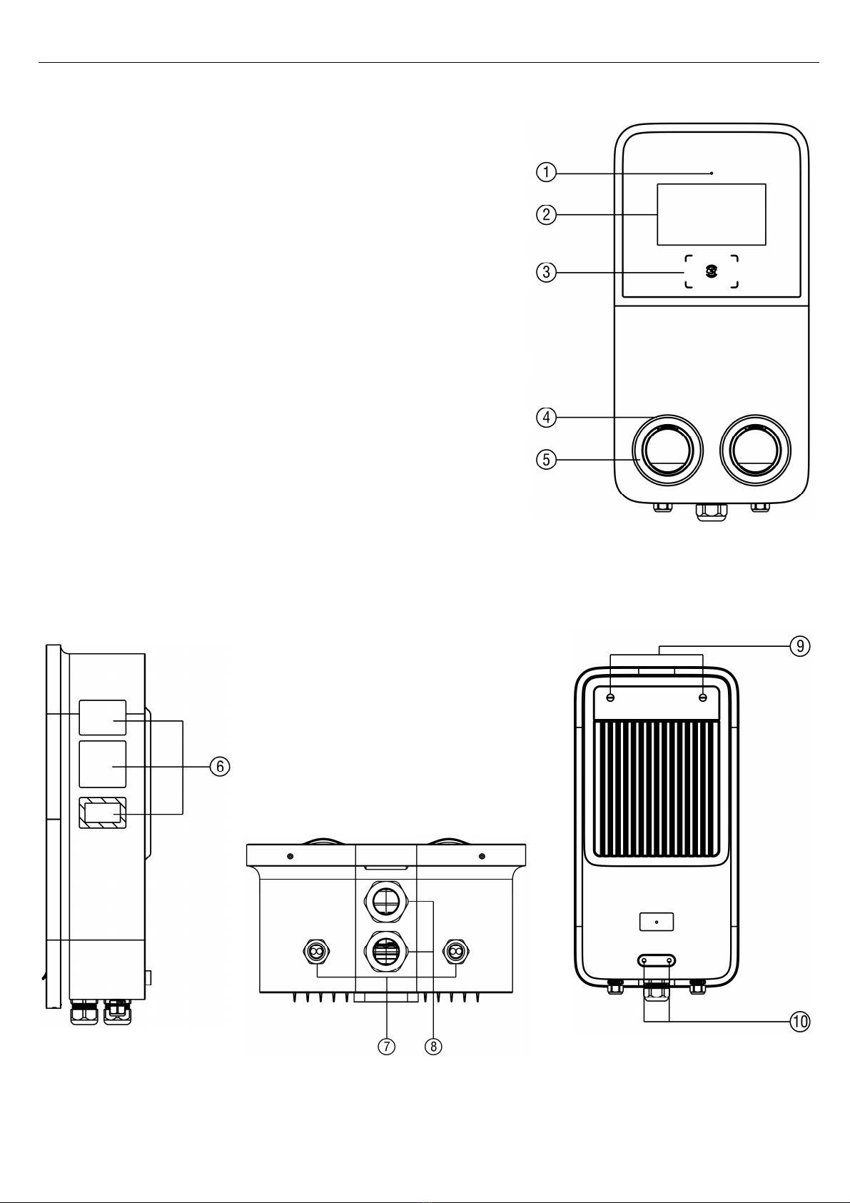
3.1 P
RODUCT
O
VERVIEW
............................................................................................................................................ 5
3.2 I
N THE
B
OX
......................................................................................................................................................... 6
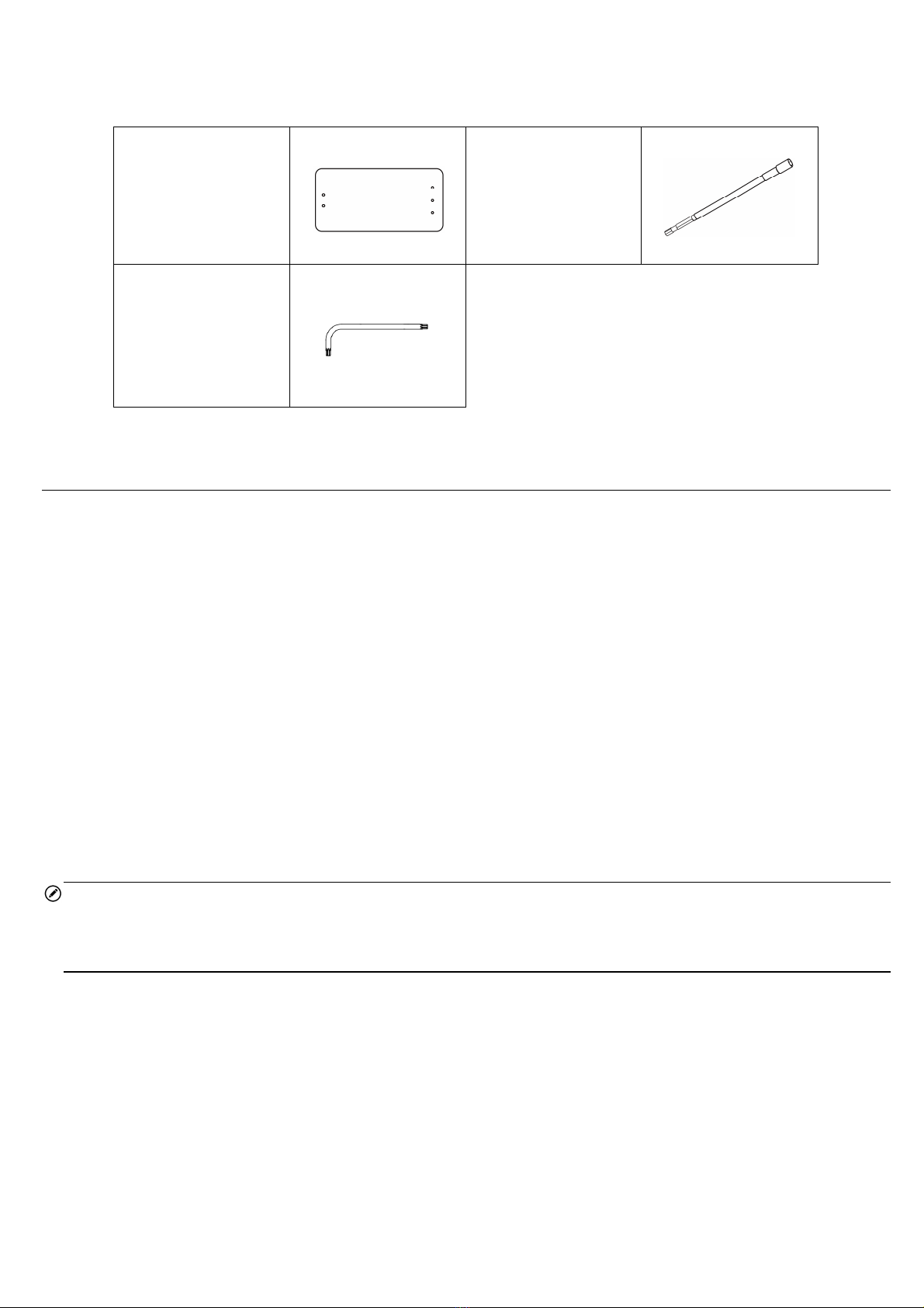
3.3 R
ECOMMENDED
T
OOL
......................................................................................................................................... 7
4 INSTALLATION ...................................................................................................................................... 8
4.1 P
REPARE FOR
I
N TALLATION
................................................................................................................................... 8
4.2 U
NPACK
............................................................................................................................................................. 9
4.3 M
ECHANICAL
I
N TALLATION
................................................................................................................................. 10
4.4 P
OWER
UPPLY
W
IRING
...................................................................................................................................... 18
4.5 C
ONNECTING TO THE
I
NTERNET
............................................................................................................................. 19
4.6 C
OMPLETE
I
N TALLATION
..................................................................................................................................... 20
4.7 E
NERGIZE THE
C
HARGING
TATION
........................................................................................................................ 20
5 SETTINGS ........................................................................................................................................... 21
5.1 I
NITIAL
ETUP
................................................................................................................................................... 21
5.2 C
HANGE THE
D
EFAULT
ETTING
........................................................................................................................... 23
6 OPERATION ........................................................................................................................................ 26
6.1 C
HARGING
O
PERATION
...................................................................................................................................... 26
6.2 D
I PLAY
D
E CRIPTION
........................................................................................................................................ 27
7 TROUBLESHOOTING ........................................................................................................................... 30
7.1 T
ROUBLE HOOTING
T
ABLE
................................................................................................................................... 30
8 SPECIFICATIONS ................................................................................................................................. 31
8.1 P
RODUCT
PECIFICATION
.................................................................................................................................... 31
8.2 LED
D
E CRIPTION
............................................................................................................................................. 32
8.3 P
RODUCT
D
IMEN ION
........................................................................................................................................ 32
9 COMPLIANCE ..................................................................................................................................... 34

1
1
Using This Manual
This manual describes the installation and use of the MaxiCharger AC Ultra. Prior to installation, read through
this manual to be familiarized with the instructions of this MaxiCharger to ensure a successful installation and
smooth operations.
1.1 Conventions
The following conventions are used.
1.1.1 Bold Text
Bold text is used to highlight selectable items such as buttons and menu options.
1.1.2 Notes and Important Messages
Notes
A NOTE provides helpful information such as additional explanations, tips, and comments.
Important
IMPORTANT indicates a situation which, if not avoided, may result in damage to the test equipment or vehicle.
1.1.3 Hyperlink
Hyperlinks or links that take you to other related articles, procedures, and illustrations are available in
electronic documents.
1.1.4 Illustrations
Illustrations used in this manual are only examples; the actual product(s) or screens may vary.
1.1.5 Revision History
Version Date Descriptions
V1 Initial version

2
2
Safety
For your own safety and the safety of others, and to prevent damage to the charging station and vehicles upon
which it is used, it is important that the safety instructions presented throughout this manual be read and
understood by all persons operating or coming into contact with the charging station.
2.1 Safety Messages
afety messages are provided to help prevent personal injury and equipment damage. All safety messages are
introduced by a single word indicating the hazard level.
DANGER
Indicates an imminently hazardous situation with a high risk level which, if the danger is not avoided, will
cause death or serious injury.
ARNING
Indicates a potentially hazardous situation with moderate risk level which, if the warning is not obeyed, can
cause death or serious injury.
CAUTION
Indicates a potentially hazardous situation with a medium risk level which, if the caution is not obeyed, may
cause minor or moderate injury or damage to the equipment.
2.2 Safety Instructions
The safety messages herein cover situations Autel is aware of. Autel cannot know, evaluate or advise you as
to all of the possible hazards. You must be certain that any condition or service procedure encountered does
not jeopardize your personal safety.
SAFETY ARNINGS
Read and follow all warnings and instructions before installing and operating the MaxiCharger.
Only a qualified electrician is allowed to install, service, repair and relocate the MaxiCharger.
The user must not attempt to service or repair the MaxiCharger as it does not contain user-serviceable
parts.
witch off input power before installing the MaxiCharger. Keep the power off until it is fully installed and
secure.
Do not use explosive or readily flammable substances near the MaxiCharger.
Do not use the MaxiCharger if the charging cable is frayed, broken or otherwise damaged, or fails to
operate.
Do not use the MaxiCharger if the enclosure or the EV connector is frayed, broken or otherwise damaged,
or fails to operate.
In the event of danger and/or an accident, a qualified electrician must immediately disconnect the
electrical supply from the MaxiCharger.

3
Refer to the vehicle user manual to check if the vehicle releases hazardous or explosive gases when
charging.
Follow the instructions given in the vehicle user manual before choosing the charging location of the
MaxiCharger.
Do not direct powerful water jets toward the MaxiCharger.
Do not operate the MaxiCharger with wet hands.
Do not put the charging handle into any liquid.
Do not install or open the MaxiCharger in wet environment (such as rain or heavy fog).
Ensure that the charging cable is positioned so that it will not be stepped on, tripped over, driven over or
otherwise subjected to excessive force or damage. Where applicable, ensure that the charging cable is
correctly stowed when not in use and that the charging handle does not touch the ground.
Keep the charging handle away from heat sources, dirt or water.
Use this MaxiCharger to charge compatible electric vehicles only. Refer to the technical specifications in
this manual. Refer to the vehicle manual to check if the vehicle is compatible.
Only use the MaxiCharger under the specified operating conditions in this manual.
Local regulations may be applicable and may vary depending on your region/country of use. The qualified
electrician must always ensure that the MaxiCharger is installed in accordance with the local regulations.
CAUTION
Ensure that the charging cable is not damaged or tangled prior to use.
Do not insert fingers into the charging port.
Do not leave objects inside the charging port.
Keep and use (electro) magnetic devices at a safe distance from the MaxiCharger.
2.3 Disposal Instructions
Handling waste incorrectly can have a negative effect on the environment and human health due to potential
hazardous substances. Discard the charging station correctly can facilitate the reuse and recycling the
materials and environmental protection.
Obey the local rules when discarding parts, packaging materials or the charging station.
Discard electrical and electronic equipment separately in compliance with the WEEE-2012/19/EU
Directive on waste of electrical and electronic equipment.
Do not mix or dispose the charging station with the household waste.

4
3
General Introduction
This MaxiCharger AC Ultra is designed to charge an electric vehicle (hereinafter called “EV”). Tailored for
commercial use, it features fast and efficient charging experience while offering best-value design and smart
charging.
This manual will instruct you on how to install and use this charging station.
Intended Use
The MaxiCharger AC Ultra is intended for the AC charging of EVs. It is intended for both indoor and outdoor
use.
DANGER
If you use the charging station in any way other than described in this manual or other related documents,
possible death, injury and damage to property can occur.
Use the charging station only as intended.
NOTE
The images and illustrations depicted in this manual may differ slightly from the actual ones.

5
3.1 Product Overview
MaxiCharger AC Ultra
1. Ambient Light ensor — detects ambient brightness
2. Display
3. RFID Reader
4. tatus LED (Refer to 8.2 LED Descriptions for details)
5. ocket
6. Product Label
7. Ethernet Cable Port
8. AC Inlet Hole
9. Upper Mounting crew
10. Mounting Hole

6
3.2 In the Box
Main Kit
Charging tation
1 PC
Wall Dock
1 PC
crew (M6 x 50)
(For wall-mounting
only)
5 PC
Wall Anchor
(For wall-mounting
only)
5 PC
Quick Reference
Guide
1 PC
Packing List
1 PC
Pedestal Kit
Pedestal
1 PC
Expansion Bolt
(M16 x 150)
4 PC
crew (M6 x 16)
3 PC
crew (M6 x 25)
2 PC
T25 crewdriver
1 PC
Drilling Template
1 PC
Quick Reference
Guide
1 PC
Packing List
1 PC

7
Tool Kit
Drilling Template
(For wall-mounting
only)
1 PC
ocket Wrench
1 PC
T10 crewdriver
1 PC
3.3 Recommended Tools
Tape measure
pirit level
Pencil
8 mm drilling bit
Drill
Wire stripper
Crimp Connector
Crimping plier
Phillips screwdriver
NOTE
The tools mentioned above are not included in the package. Ensure they are readily available prior to
installation.

8
4
Installation
4.1 Prepare for Installation
4.1.1 Choose Location
For all-mounting:
Install the charging station on a flat and vertical surface capable of supporting its weight (e.g. a finished
brick or concrete wall).
Install the charging station in a location that allows the charging cable to remain within its bending
tolerance.
The charging station should be installed 450 mm above the surface at a minimum.
Position the charging station in a location where it is not vulnerable to being damaged.
For Pedestal-mounting:
A horizontal, level, and sound foundation is required for installation. To ensure safe and permanent
anchoring, the concrete strength level should be above C30.
The base must permit the running off of any water that has entered the base.
The diameter of the embedded cable should not exceed 110 mm. All cables must be laid precisely in the
center of the concrete foundation from the base and should have an excess length of 1-1.5 m for the
remaining installation activities.
Do not mount the pedestal on asphalt.
The foundation can be flush with the surface.
4.1.2 Checklist
The local installation regulations are identified and followed.
All necessary permits are obtained from the local authority that has jurisdiction.
The existing electrical load has been calculated to find the maximum operating current for the charging
station installation.
A miniature circuit breaker (MCB) and residual current device (RCD) are installed upstream and have
ratings that correspond to the local power supply and required charging power.
The correct cables are available at the installation site, and there is sufficient cable length to strip and
connect the wires.
The recommended installation tools are available at the site. Refer to 3.3 Recommended Tools.

9
4.1.3 Electrical Design
DANGER
Connecting the MaxiCharger to the power supply other than specified in this section can cause incorrect
installation and the risk of electric shock, as well as damage to the charging station, and injury or death.
Earthing System
TN-system PE cable
TT-system
IT-system
Earth electrode installed
separately (self-installed)
Power Input Three-phase 400 V AC ± 15%, 50 Hz
MCB (Miniature Circuit Breaker) The power supply MCB must match the power rating of the
charging station.
Observe the descriptions below for power supply connection of the charging station, depending on the
specifications of the power supply cabinet.
400 V AC, Three-phase with Neutral
For three-phase using a Wye-connected secondary, all three phases (L1, L2, and L3) and neutral must be
connected. Each phase voltage must measure 230 V to neutral.
4.2 Unpack
1. Open the package.
2. Remove the charging station from the box.
3. Remove all packaging material from the charging station.
4. Discard the packaging material.
5. Ensure that all parts are delivered according to the order. Refer to 3.2 In the Box.
6. Do a visual inspection of the charging station and the parts for damage. In case any damage is found or
the parts are not consistent with your order, contact the delivery and Autel support.

10
4.3 Mechanical Installation
There are two ways to mount the charging station:
Mounting on a wall
Mounting on a pedestal
4.3.1 Mounting on a all
STEP 1
1. Place the drilling template against the wall, minimum 450 mm above the surface. Then level it using a
spirit level.
2. Mark the five mounting holes with a pencil and remove the template.
STEP 2
1. Drill five 8 mm holes to a depth of 50 mm.
2. Insert five 8 mm wall anchors into the holes.
3. Place the wall dock on the wall, aligning with the three upper holes. Level it with a spirit level. Then insert
three M6 x 50 screws into the holes. Tighten the screws to 5-7 Nm using the socket wrench.

11
STEP 3
Attach the charging station onto the wall dock by inserting the two mounting screws (B) on the back of the
charging station into the two upper mounting holes (A). lide the charging station downwards to engage the
screws.
STEP 4
Loosen the two M3 x 8 screws (A) at the bottom of the charging station using the T10 screwdriver and remove
the faceplate (B). Set them aside.

12
STEP 5
Remove the eight M3 x 8 screws using the T10 screwdriver. Set them aside.
STEP 6
Flip the maintenance cover up. Then insert two M6 x 50 screws into the two lower holes. Tighten the screws
to 5-7 Nm using the socket wrench to secure the charging station.

13
4.3.2 Mounting on a Pedestal
Preparing the Foundation
STEP 1
1. Dig a hole with the size of 460 x 300 x 250 mm (L x W x H).
2. Trench and excavate an opening to accommodate the wiring conduit.
STEP 2
1. Run the conduit to the designated location. The conduit stub-up is recommended 100 mm above the
surface at a minimum.
2. Pour concrete into the hole and wait until it has hardened.
3. Feed the AC input cable and the Ethernet cable (if available) out of the conduit. Ensure a length of 1-1.5m
is available above the foundation to allow wiring to reach the AC terminals.

14
Drilling Holes
1. Place the drilling template on the foundation, aligning its central hole with the conduit stub-up. Then level
the template using a spirit level.
2. Mark the four mounting holes on the foundation. Remove the drilling template.
3. Drill into the holes measuring 18 mm in diameter and 160 mm in depth.
Installing the Pedestal
STEP 1
Loosen the four M5 x 20 security screws on both sides using the T25 screwdriver to remove the upper and
lower front covers. Set them aside.

15
STEP 2
1. Place the pedestal onto the foundation, aligning with the conduit stub-up and four mounting holes.
2. Tap the included M16 x 150 expansion bolts into the four mounting holes. Tighten the bolts to 140 Nm to
secure the pedestal.
Mounting the all Dock
1. Align the wall dock with the three mounting holes on the pedestal.
2. Insert the three included M6 x 16 screws into the holes and tighten them to 5-7 Nm using the socket
wrench.

16
Mounting the Charging Station
Hang the charging station onto the wall dock by aligning the two mounting screws (A) on the back of the
charging station with the two holes (B) of the wall dock.
Securing the Charging Station
STEP 1
Loosen the two M3 x 8 screws (A) at the bottom of the charging station using the T10 screwdriver and remove
the faceplate (B). Set them aside.

17
STEP 2
Remove the eight M3 x 8 screws using the T10 screwdriver. Set them aside.
STEP 3
Flip the maintenance cover up. Then insert two M6 x 25 screws into the two lower holes. Tighten the screws
to 5-7 Nm using the socket wrench to secure the charging station.
Table of contents
Other Autel Accessories manuals