Autel MaxiVideo MV201 User manual

Table of Contents
1. Safety Instructions ............................................................................1
1.1 Work Area Safety....................................................................1
1.2 Electrical Safety.......................................................................1
1.3 Personal Safety........................................................................2
2. Description, Specifications and Tool Components.........................3
2.1 Description...............................................................................3
2.2 Specifications...........................................................................3
2.3 Accessories Included...............................................................4
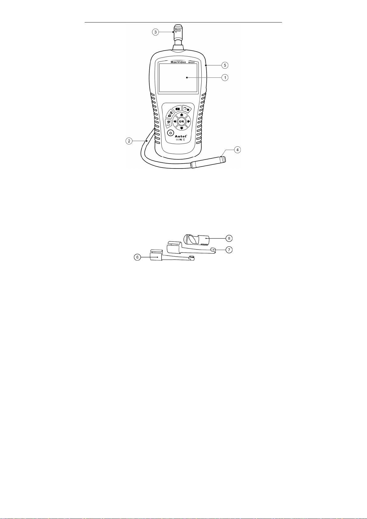
2.4 Tool Components ....................................................................4
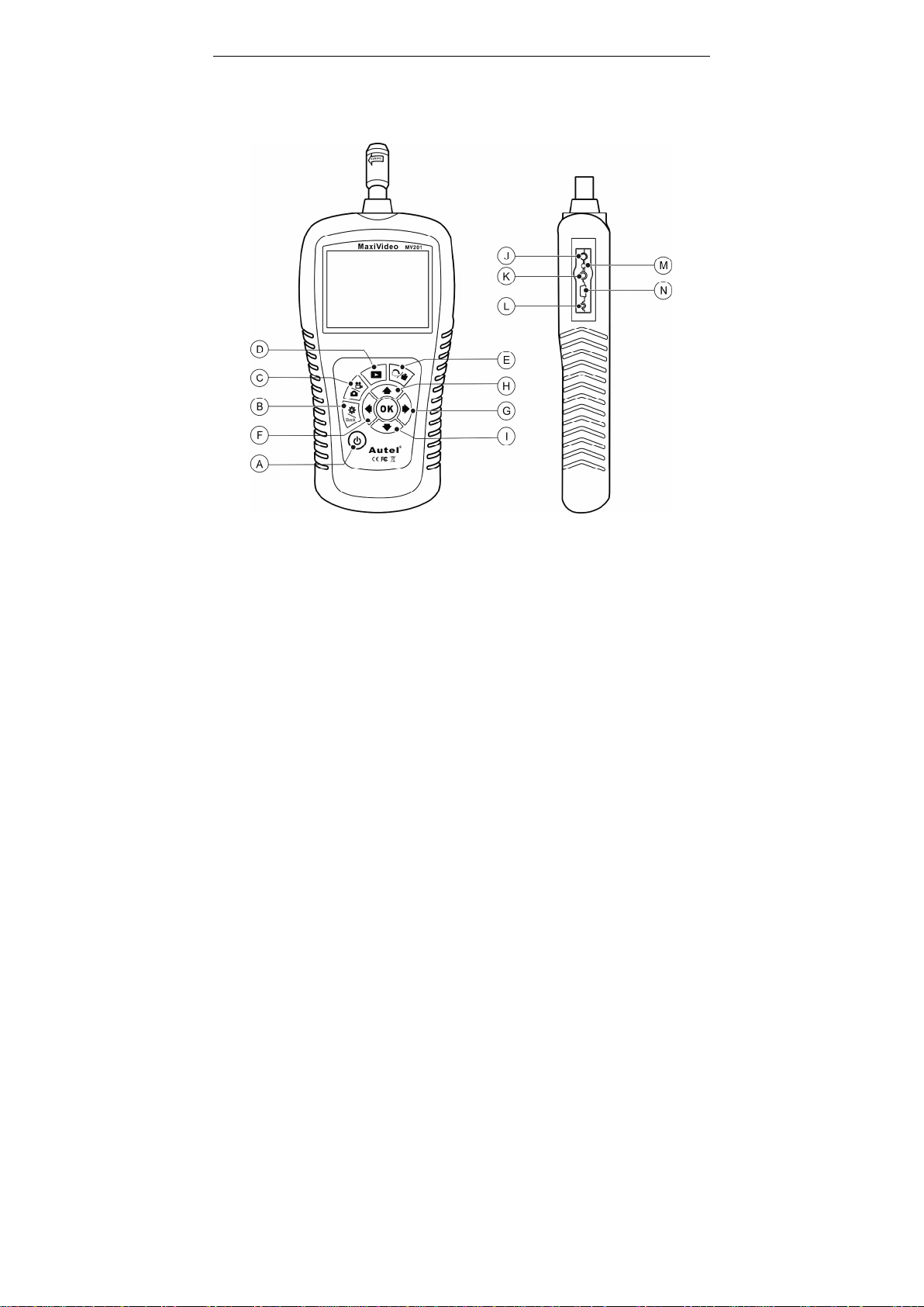
2.5 Buttons and Ports....................................................................6
3. Installation and Connection.............................................................8
3.1 The Imager Head and Cable Installation..............................8
3.2 Accessories Installation...........................................................8
3.3 SD Card Installation...............................................................9
3.4 USB Cable Connection ...........................................................9
3.5 Video-Out Cable Connection .................................................9
3.6 Earphone Connection .............................................................9
4. Battery Charging Precautions........................................................11
4.1 Battery Charging Safety.......................................................11
4.2 Battery and Charger Specifications.....................................11
4.3 Charger Inspection................................................................12
4.4 Battery Charging Procedures ..............................................12
5. Operation Instructions....................................................................14
5.1 Basic Operation.....................................................................14
5.2 Operation Precautions..........................................................15
5.3 Tool Inspection......................................................................16
5.4 Tool and Work Area Set-Up ................................................17
5.5 On Screen Navigation...........................................................19
5.6 Icons........................................................................................25
5.7 Software Update....................................................................32
6. Troubleshooting ..............................................................................33
7. Warranty Information....................................................................34
7.1 Limited One Year Warranty................................................34
7.2 Service Procedures................................................................34

Safety Instructions WorkArea Safety
1
1. Safety Instructions
IMPORTANT: To prevent electric shock, fire and/or personal injury
or damage, read this user’s manual first and observe the following
safety instructions.
1.1 WorkArea Safety
lAlways perform automotive testing in a safe environment.
lKeep your work area clean and well lit. Cluttered benches and
dark areas may cause accidents.
lKeep clothing, hair, hands, tools, test equipment, etc. away from
all moving or hot engine parts.
lOperate the tool in a well-ventilated work area.
lDo not operate the tool in explosive atmospheres, such as in the
presence of flammable liquids, gases, or heavy dust.
lKeep a fire extinguisher suitable for gasoline/chemical/electrical
fires nearby.
lDo not use the tool around corrosive chemicals which can ruin
the photo quality.
lKeep bystanders, children and visitors away while operating the
tool.
lKeep the tools dry, clean, free from oil, water and grease. Use a
mild detergent on a clean cloth to clean the outside of the tool
when necessary.
1.2 Electrical Safety
lAvoid body contact with earthed or grounded surfaces such as
pipes, radiators, ranges and refrigerators.
lDo not expose the tool to rain or wet conditions. Water entering
the tool will increase the risk of electric risk.
lDo not abuse the cord. Never use the cord for carrying, pulling,
or unplugging the tool. Keep cord away from heat, oil, sharp
edges or moving parts.
lIf operating the tool in a damp location is unavoidable, use a
ground fault circuit interrupter (GFCI) to protect supply.

Safety Instructions Personal Safety
2
1.3 Personal Safety
lDo not use the tool while tired or under the influence of drugs,
alcohol, or medications. A moment of interruption can result in
serious personal injury.
lDo not over-reach. Keep proper footing and balance at all times.
Proper footing and balance enables better control of the tool in
unexpected situations.
lAlways wear safety eye protection that meets ANSI standards.
lDo not wear loose clothing or jewelry. Keep your hair, clothing,
and gloves away from moving parts. Loose clothes, jewelry, or
long hair can be caught in moving parts.
lDo not place the tool on any unstable cart or surface. The tool
may fall causing serious injury to a person or serious damage to
the tool itself.
lNever spill liquid on the display units. Liquid increases the risk
of electric shock and damage to the tool.
lDo not use the tool for personal or medical use in any way.
lThe product is not shock-resistant. Do not use it as a hammer or
drop it.

Description, Specification and Tool Components Description
3
2. Description, Specifications and Tool
Components
2.1 Description
The premier Digital Inspection Videoscope MaxiVideoTM MV201 is
an ideal and powerful tool for inspecting difficult-to-reach areas
normally hidden from sight. It is a completely digital platform that
features the function of capturing and recording photos and videos
either on its internal memory or on the removable SD cards. The
ergonomic tool not only features a 3.5" full color LCD screen,
multi-language interface and viewing capacity as close as 3/8" with
crystal clear output, but also offers the capacity to view real time
images directly connected to a TV and upload captured photos and
videos to a PC. Accessories (magnet, hook and mirror) are included to
attach to the imager head to provide application flexibility.
2.2 Specifications
Recommended
use Indoor
Optimal viewing
Distance 3/8" to 12" (0.95cm to 30cm)
Image capture JPG images (1280 x 1024)
AVI videos (320 x 240)
Screen type
display 3.5" TFT LCD
Display
resolution 320 x 240
Power supply Built-in rechargeable lithium-ion battery
pack (3.7 Volt)
Tested battery
life 5-6 hours of continuous use
Dimensions 9255 x 108 x 36mm (10"x 4.25"x 1.42")
Weight Net: 0.6 kg (1.3 lbs);
Gross: 2.6 kg (5.7 lbs)

Description, Specification and Tool Components Specifications
4
Recording
medium Internal memory or SD card (SD card is
optional and not included)
Image controls Zoom, low light vision
Lighting Fully adjustable LED
1Cable reach 1m (3') -- expandable to 6m (19')
w/optional extensions
Imager head 8.5mm (0.33") is standard;
16mm (0.63") and
5.5mm (0.22") are optional.
1waterproof 1Imager head and cable to 3m (10')
1Additonal ports USB, video out and earphone ports
Operating temp. Main unit: 32°F to 113°F (0°C to 45°C);
Cable: 14°F to 176°F (-10°C to 80°C)
Storage temp. 1-4°F to 158°F (-20°C to 70°C)
Operating
humidity 5% - 95% non-condensing (display unit)
Video output RCA
2.3 Accessories Included
1) Protective carrying case
2) User’s Manual
3) Imager head and cable (8.5mm)
4) Magnet, hook and mirror
5) Charger
6) USB cable
7) Video-out cable
2.4 Tool Components
1Note: Because of continuing improvements, actual product may
differ slightly from photo.
The MaxiVideoTM MV201 comes with the following items:

Description, Specification and Tool Components Tool Components
5
Fig. 1
1) LCD Screen – Indicates still images and videos.
2) Cable – Connects to the tool while in use.
3) Cable Connector – Connects the display unit to the imager head
and cable.
4) 1Imager Head – Connects to the cable to view real-time images.
5) Rubber Boot – Protects the tool from drop, abrasion, etc.
Fig. 2
6) Accessory Magnet – Picks up small metal objects such as
dropped rings or screws on the floor.
7) Accessory Hook – Unclogs obstacles and picks up wires in the
pipes or confined areas.
8) Accessory Mirror – Helps users look around corners and see

Description, Specification and Tool Components Tool Components
6
inside the unreachable areas.
2.5 Buttons and Ports
Fig. 3
A. Power Button – Turns on/off the tool.
B. Setting/Back Button – Moves to the primary settings screen,
while pressing again will return to the last viewed screen.
C. Camera/Video Button – Helps capturing a photo while pressing
again will capture a video.
D. Play Button – Moves to play captured photos and videos.
E. Trash Can/Reverse Button – Deletes captured photos and
videos in the play mode. Pressing again will control the direction
of the real-time image and video in the live screen. The real-time
image and video will do a horizontal reverse or a vertical reverse.
F. LEFT Arrow LED Lighting Adjusting Button – Uses left
arrow button to increase LED brightness in the camera mode.

Description, Specification and Tool Components Buttons and Ports
7
G. RIGHT Arrow LED Lighting Adjusting Button – Uses right
arrow button to decrease LED brightness in the camera mode.
H. UP Arrow Zoom Adjusting Button – Uses up arrow button to
zoom in while in the camera mode.
I. DOWN Arrow Zoom Adjusting Button – Uses down arrow
button to zoom out while in the camera mode.
J. DC Power Source Port – Connects the tool to the mains with
the supplied charger for battery charging.
K. Video-out Port – Connects the tool to a TV with the supplied
video-out cable to view the real-time image.
L. Earphone Port – Inserts the optional earphone with microphone
into the earphone port to help recording.
M. Charging Indicator Light – When the battery is charging, the
charging indicator light will be red. When the battery is fully
charged, the charging indicator light will be green.
N. 1Mini USB Port – Connects the tool to a computer with the
supplied USB cable to upload and view captured photos and
videos.

Installation and Connection The Imager Head and Cable Installation
8
3. Installation and Connection
3.1 The Imager Head and Cable Installation
To use the tool, the imager head and cable must be connected to the
display unit. To connect the cable to the display unit, make sure the
key and slot (Fig. 4) are properly aligned. Once they are aligned,
finger-tighten the knurled knob to hold the connection firmly in place.
Fig. 4
3.2 Accessories Installation
The three accessories include magnet, hook and mirror (Fig. 2). All are
attached to the imager head in the same manner. Hold the accessory
and the imager head as shown in Fig. 5.
Fig. 5
Slip the end of the accessory over the tip of the imager head to fix the
accessory as shown in Fig. 6.

Installation and Connection Accessories Installation
9
Fig. 6
3.3 SD Card Installation
NOTE: SD card slot provides for additional memory, but SD card is
optional and not included. Different SD cards can be used to insert
into the SD card slot.
To insert an SD card into the SD card slot, make sure the contacts are
facing towards slot and the angled portion of the card is facing down.
When the SD card is installed, a small SD card icon will appear at the
top right portion of the screen. To remove an SD card, gently push the
SD card inward and then release to eject it from the card slot.
3.4 USB Cable Connection
Use the supplied USB cable to connect the tool to a PC to upload and
view captured photos and videos. A “USB Connected” message will
appear on the screen as shown. (Fig. 7)
Fig. 7

Installation and Connection Video-Out Cable Connection
10
3.5 Video-Out Cable Connection
Insert the video-out cable into the video-out port of the tool and the
other end of the cable into the video-in port of a TV, the LCD screen
will output a high quality real-time image.
3.6 Earphone Connection
Connect the optional earphone with microphone to the earphone port
of the tool, while speak to the microphone to record your voice.

Battery Charging Precautions Battery Charging Safety
11
4. Battery Charging Precautions
BIMPORTANT: To reduce the risk of serious injury, read these
precautions and the label on charger’s surface carefully before
using.
4.1 Battery Charging Safety
lDo not probe charger with conductive objects.
lDo not use charger if it has been dropped or damaged in any
way.
lCharge battery in temperatures above 41°F (5°C) and below
113°F (45°C).
lWhen in use, the charger shall be kept out of heat, high voltage
and avoided children’s touching.
lUse the supplied charger. Do not charge the battery over 24
hours.
lDo not allow anything to cover the charger while in use.
lUnplug the charger from outlet before attempting any
maintenance or cleaning.
lDo not store charger in damp, wet or explosive environment.
lDo not open charger housing. Have repairs performed only at
authorized locations.
lDo not charge battery near fire or in the sunlight.
lProper care will prevent serious damage to the charger.
4.2 Battery and Charger Specifications
Input 100-240 VAC/12 VDC 50/60Hz
Output 5V DC
Battery Type 3.7V lithium-ion
Battery Capacity
4200 mA
Input Current 0.3A/1A (DC)
Charging Time 5-6 hours
Cooling Passive convention cooling (No fan)

Battery Charging Precautions Charger Inspection
12
4.3 Charger Inspection
CAUTION: Before using, inspect the charger and correct any
problems. Set up charger according to these procedures to reduce
the risk of injury from electric shock, fire and other causes and
prevent tool damage.
1) Make sure charger is unplugged. Inspect the power cord and
charger for damage or modifications, or broken, worn, missing,
misaligned or binding parts. If any problems are found, do not
use the charger until the parts have been repaired or replaced.
2) Clean any oil, grease or dirt from the tool especially on the
buttons. This helps prevent the tool from slipping from your
hands and allows proper ventilation.
3) Inspect if the warning label on charger’s surface is intact and
readable.
4) Select appropriate location for charger before using. Check work
area for:
uThe charger must be between 41°F (5°C) and 113°F
(45°C) for charging. If the temperature of either is outside
of this range at any point during charging, the operation will
be suspended until brought back to the correct temperature
range.
uInspect that the plug fits correctly into the desired outlet.
uThe charger needs a clearance of at least 4" (10 cm) on all
sides to maintain a proper operating temperature.
4.4 Battery Charging Procedures
NOTE: New battery reaches full capacity after approximately 5
charging and discharging cycles.
The tool has a 3.7V built-in lithium-ion rechargeable battery. When
the battery is low, a “Battery critically low!” message appears and
suggests you to charge the battery in time. (Fig. 8)

Battery Charging Precautions Battery Charging Procedures
13
Fig. 8
There are two means of charging battery:
1) To charge battery by charger: Locate the DC power
source port of the tool. With dry hands, connect the tool to the
mains with charger to start charging.
2) To charge battery by USB cable: Locate the USB port of the tool.
With dry hands, connect the tool to a PC with USB cable to start
charging.
uThe battery will begin charging automatically. While the
battery is charging, the charging indicator light will be red.
uWhen the battery is fully charged, the charging indicator light
will be green.
uOnce the battery is charged, it may remain until it is ready to be
used. There is no risk of over-charging the battery. When the
battery has been fully charged, the charger automatically
switches to retention charging.
uUnplug charger from outlet once charging completes.

Operation Instructions Basic Operation
14
5. Operation Instructions
1IMPORTANT: Always wear safety eye protection to protect your eyes
against dirt and other objects. Follow operation instructions to
reduce the risk of injury from electric shock, entanglement and other
causes.
5.1 Basic Operation
NOTE: When in operation, the cable can be bent into a certain shape.
This may help you operate the cable into confined areas.
1) Hold the tool with LCD screen facing you and press Power
button to turn it on. Wait for two seconds, the first screen – a
splash screen is booting up, and then appear a live screen where
you can do most of your work.
2) Press OK button to capture photos in the camera mode; Press OK
button to begin capturing videos in the video mode. You should
press Camera/Video button to switch the two modes as you
desired.
3) Press UP and DOWN arrow buttons to zoom in or out while in
the camera mode where you can see a zoom indicator bar as you
adjust zoom.
4) Press LEFT and RIGHT arrow buttons to increase or decrease
LED brightness while in the camera mode where you can see a
brightness indicator bar as you adjust LED light intensity.
5) Press Play button to view captured photos and videos.
6) Press Trash Can button to delete captured photos and videos as
you needed when play back captured photos and videos.
7) Press Reverse button to control the direction of the real-time
image and video as you needed in the live screen.
8) Press Setting/Back button to Setup mode or return to the last
viewed screen.
9) Use the supplied accessories to provide application flexibility.
10) Use the supplied USB cable to connect the tool to a PC to upload
and view captured photos and videos.
11) Connect the supplied video-out cable to video-out port of the tool
and the other end of the cable to the video-in port of a TV to view

Battery Charging Precautions Basic Operation
15
a high quality real-time image.
12) Connect the optional earphone with microphone to the earphone
port of the tool, while speak to the microphone to record your
voice.
5.2 Operation Precautions
lUse the tool only as directed. Do not operate the tool unless the
user’s manual has been read thoroughly and proper training has
been completed.
lThe display unit is not waterproof. The imager head and cable
are waterproof, but not acid-proof or fireproof. Avoid
submersing the imager head and cable into corrosive, oily places
and be sure to keep the imager head and cable away from high
temperature objects.
lDo not immerse the tool and display unit in water. Such
measures reduce the risk of electric shock and damage.
lDo not use excessive force to insert or withdraw the imager head
and cable. This may result in damage to the tool or inspection
area.
lDo not use the imager head and cable to modify surroundings,
clear pathways or clogged areas.
lDo not place the imager head and cable into anything or
anywhere that may contain a live electric charge or moving parts,
which increase the risk of electric shock or entanglement
injuries.
lDo not use the tool for personal inspection or medical use in any
way. This is not a medical tool.
lDo not eat or smoke while operating the tool. Use hot, soapy
water to wash hands and other body parts exposed to drain
contents after using the tool to inspect drains and other areas that
may contain chemicals or bacteria, which will help prevent
contamination with toxic or infectious material.
lWhen the inspection is completed, carefully withdraw the imager
head and cable from inspection area.
lStore idle components out of the reach of children and other
untrained persons.
lMaintain the tool with care. Properly maintained tools are less

Operation Instructions Operation Precautions
16
likely to cause injury.
lDo not drop the tool, if the tool is dropped accidently, check for
the breakage and any other conditions that may affect its
operation.
lUse only accessories that are recommended by the manufacturer
for the tool.
lDry your hands when operating the tool or charging the battery.
lAlways use appropriate personal protective equipment while
handling and using the tool. Appropriate personal protective
equipment always includes safety glasses and gloves, and may
include latex or rubber gloves, face shields, goggles, protective
clothing, respirators and steel toed footwear.
lProtect against excessive heat. The tool should be kept away
from heat sources such as radiators, stoves or others that produce
heat. Do not use the tool near moving machinery or areas where
the temperature will exceed 113°F (45°C).
lStore the tool, charger and all cables in a locked area out of the
reach of children and people unfamiliar with tool.
5.3 Tool Inspection
WARNING: Before using, inspect your tool and correct any
problems to reduce the risk of serious injury from electric shock and
other causes and prevent tool damage.
lMake sure the power is OFF.
lClean any oil, grease or dirt from the tool, especially on the
buttons and ports. This helps prevent the tool from slipping from
your hands.
lInspect the imager head lens for condensation. To avoid
damaging the tool, do not use the tool if condensation forms
inside the imager head. Let the water evaporate before using
again.
lInspect the full length of the cable for cracks or damage. A
damaged cable could allow water to enter the tool and increase
the risk of electric shock.
lMake sure the connections between the display unit and imager
head and cable are tight. All connections must be properly

Battery Charging Precautions Tool Inspection
17
assembled for the cable to be waterproof.
lCheck if the warning label is present, firmly attached and
readable. Do not operate the tool without the caution label.
lTurn on the power and make sure the tool model through the
splash screen and then display the live screen.
lIf the tool does not work well after turning it on. Please have the
tool checked by a qualified technician. Any tool that cannot be
controlled with the power button is dangerous and must be
repaired.
2NOTE: Please check following methods to avoid injury.
üFOR WALLS: For inspecting the inside walls, be sure to shut
off the circuit breaker to the whole house before using the tool.
üFOR PIPES: If you suspect a metal pipe could contain an
electric charge, have a qualified electrician to check the pipe
before using.
ü2FOR AUTOMOBILES: Be sure the automobile is not running
during inspection. Metal and liquid under the hood may be hot.
Don’t get oil or gas on the imager head.
5.4 Tool and Work Area Set-Up
CAUTION: Set up the tool and work area according to these
procedures to reduce the risk of injury from electric shock,
entanglement, and other causes and prevent tool damage.
1) Check work area for:
üSufficient lighting.
üDo not work in area until flammable sources have been
identified and corrected. The tool is not explosion proof and
can cause sparks.
üDo not use the tool while standing in water.
2) Check the area and determine if MaxiVideoTM MV201 Digital
Inspection Videoscope is the correct tool for the job.
üCheck the access points to the area.
üCheck if there is any electric power supplied to the area to
be inspected.

Operation Instructions Tool and Work Area Set-Up
18
üCheck if the any liquids will be occurred during the
inspection. The imager head and cable are waterproof to a
depth of 3m (10'). Greater depths may cause leakage into
the imager head and cable and cause electric shock or
damage the tool. The display unit is not waterproof and
should not be exposed to wet conditions.
üCheck if any chemicals are present, especially in the case of
drains. Chemicals may damage the tool.
üCheck the temperature of the area. The working temperature
of the tool is between 32°F (0°C) and 113°F (45°C).
üCheck if any moving parts are present in the area.
3) Make sure the tool has been properly inspected.
4) Install the correct accessories for use in the appropriate
application.
CAUTION: Make sure the tool has been powered off before
performing maintenance.
lTool maintenance must be performed only by qualified repair
personnel. Maintenance performed by unqualified repair
personnel could cause injury.
lWhen maintaining, use only identical replacement parts. Use of
unauthorized parts or failure to follow maintenance instructions
may create a risk of electric shock or injury.
lDo not attempt to take any pieces of the tool apart unless directed
by the manual.
lFollow instructions to change accessories.
lDo not use acetone to clean the tool. Instead, use only alcohol to
swab the connections. Avoid rubbing too hard on the LCD
screen. After using, wipe the display unit clean gently with a dry
cloth.
lUpon the completion of any maintenance of the tool, ask
qualified repair personnel to perform safety checks to examine if
the tool is in proper operating condition.
lStop using the tool if it starts smoking or emitting noxious
fumes.
lAlways handle the tool with care. It is not shock-resistant.
lDo not disassemble the tool beyond what is shown in the manual.
Doing so will void your warranty.

Operation Instructions On Screen Navigation
19
5.5 On Screen Navigation
1) Splash Screen
When the tool is powered on, the first screen displayed is
referred to as the splash screen. (Fig. 9) This screen tells you
the tool is booting up. Once the tool is fully powered up, the
screen will automatically switch to the live screen.
Fig. 9
2) Live Screen
The live screen is where you will do most of your work. A live
image of what the imager head sees is displayed on the screen.
You can zoom, adjust LED brightness, rotate images and video,
view and capture photos and videos from this screen.
3) Switching from Still Image Capture to Video Capture
The tool defaults to still image capture when powered on. Press 258B
Video/Camera button to switch between still image capture and
video capture as you needed.
4) Adjusting LED Brightness
Pressing RIGHT and LEFT arrow buttons on the key pad (in
the still camera mode) will increase or decrease the LED
brightness. A brightness indicator bar will be displayed on the
screen as you adjust brightness. (Fig. 10)
Table of contents
Popular Music Equipment manuals by other brands

MIMAKI
MIMAKI CG-AR Series installation instructions

Professional Sound Corporation
Professional Sound Corporation Press Bridge Operation manual

KIOSHI
KIOSHI INTERACTIVE PIANO SILENT SYSTEM installation guide

ARP Instruments
ARP Instruments 1601 Service manual

KETRON
KETRON Event quick guide

Palmer
Palmer PLI 04 USB quick start guide