auto maskin RIO 425 User manual

Manual# 1100276
Installation Manual
RIO 425
AC Generator Interface


Installation Manal –RIO 425 Page i
Installation Manual
for
RIO 425 –AC Generator Interface
~~~
Revision
1.0
Date
12 August 2019
Revision history:
Rev.
Date
Description
1.0
12.08.2019
Initial Release Revision (Upgraded from former QIG ver. 1)
Copyright © 2010 - 2019 by Auto-Maskin.
All rights reserved. No part of this document may be reproduced or transmitted in any form or by any
means, electronic, mechanical, photocopying, recording, or otherwise, without the prior written
permission of Auto-Maskin.
www.auto-maskin.com

Page ii
Installation Manual - RIO 425
Table of Content
DOCUMENT INFORMATION ................................ 1
ABOUT THIS MANUAL .............................................. 1
Responsibilities .............................................. 1
INSTALLATION OF THE RIO 425 ........................... 2
INTRODUCTION ...................................................... 2
OPERATING CONDITIONS.......................................... 2
WIRING ................................................................ 2
Power Supply ................................................. 2
Communication to the DCU........................... 3
Generator Voltage Interface ......................... 4
Generator Current Interface .......................... 4
CONFIGURATION .................................................... 4
Configuration from the DCU web server ....... 5
Configuration using the user interface .......... 5
SCHEMATIC ......................................................... 7
APPENDIX............................................................ 8
Setup RIO 425 communication parameters... 8

Installation Manual - RIO 425
Page 1
Document
Information
About this manual
This manual has been published
primarily for professionals and
qualified personnel.
The user of this material is assumed to
have basic knowledge in marine
systems, and must be able to carry out
related electrical work.
Work on the low-voltage circuit should
only be carried out by qualified and
experienced personnel.
Installation or work on the shore
power equipment
must only
be carried
out by electricians authorized to work
with such installations.
Responsibilities
It is the
sole responsibility of the
installer
to ensure that the installation
work is carried out in a satisfactorily
manner, that it is operationally in good
order, that the approved material and
accessories are used and that the
installation meet all applicable rules
and regulations.
Note! Auto-Maskin continuously
upgrades its products and reserves the
right to make changes and
improvements without prior notice.
Page 2
Installation Manual - RIO 425
Installation of
the RIO 425
This chapter covers installation of the
RIO 425.
Introduction
The RIO 425 is a generator interface.
The module can be connected at the
generator, or close to the generator.
Using the two-wire data interface, it
communicates its measured data to a
DCU in the Auto-Maskin Marine Pro
range.
The unit can also be used standalone
and communicate its data on the
inbuilt Modbus interface.
Operating Conditions
Operating
Temperature:
-10 °C/ +50 °C
Relative
Humidity:
5 to 95 % RH (without
condensation)
Wiring
The RIO 425 has these main
connections
AC Power Supply
Communication to the DCU
Generator voltage interface
Generator current interface
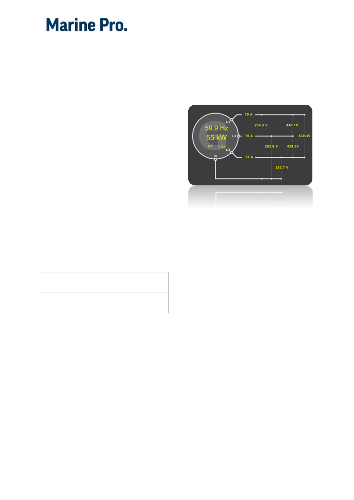
When properly connected and
communicating to the DCU on the RIO
link, the DCU will automatically detect
the RIO 425 and add an instrument
page similar to the one below.
Power Supply
AC or DC Power Supply
The RIO 425 can operate with either
AC or DC power supply.
AC Power Supply
On the RIO 425, connect an AC power
supply to terminals 14 and 15.
The supply shall be in the range 85 –
265 VAC (+10%/-15%).
DC Power Supply
On the RIO 425, connect a DC power
supply to terminals 14 (positive) and
15 (0V).
The supply shall be in the range 95 –
300 VDC (+10%/-15%).
Installation Manual - RIO 425
Page 3
Power Supply Fuse
The RIO 425 module shall be
protected with an external 2A fuse on
the supply line.
Wire Requirement
Supply wires shall have a minimum
area of 1mm2(~17 AWG).
Communication to the
DCU
The RIO 425 comes preconfigured to
communicate with the DCU
410(E)/408(E) or DCU 210(E)/208(E) in
the Auto-Maskin Marine Pro range.
It can be used together with other RIO
expansion modules on the same RIO
link.
Note! Only one RIO 425 can be used
on a RIO link.
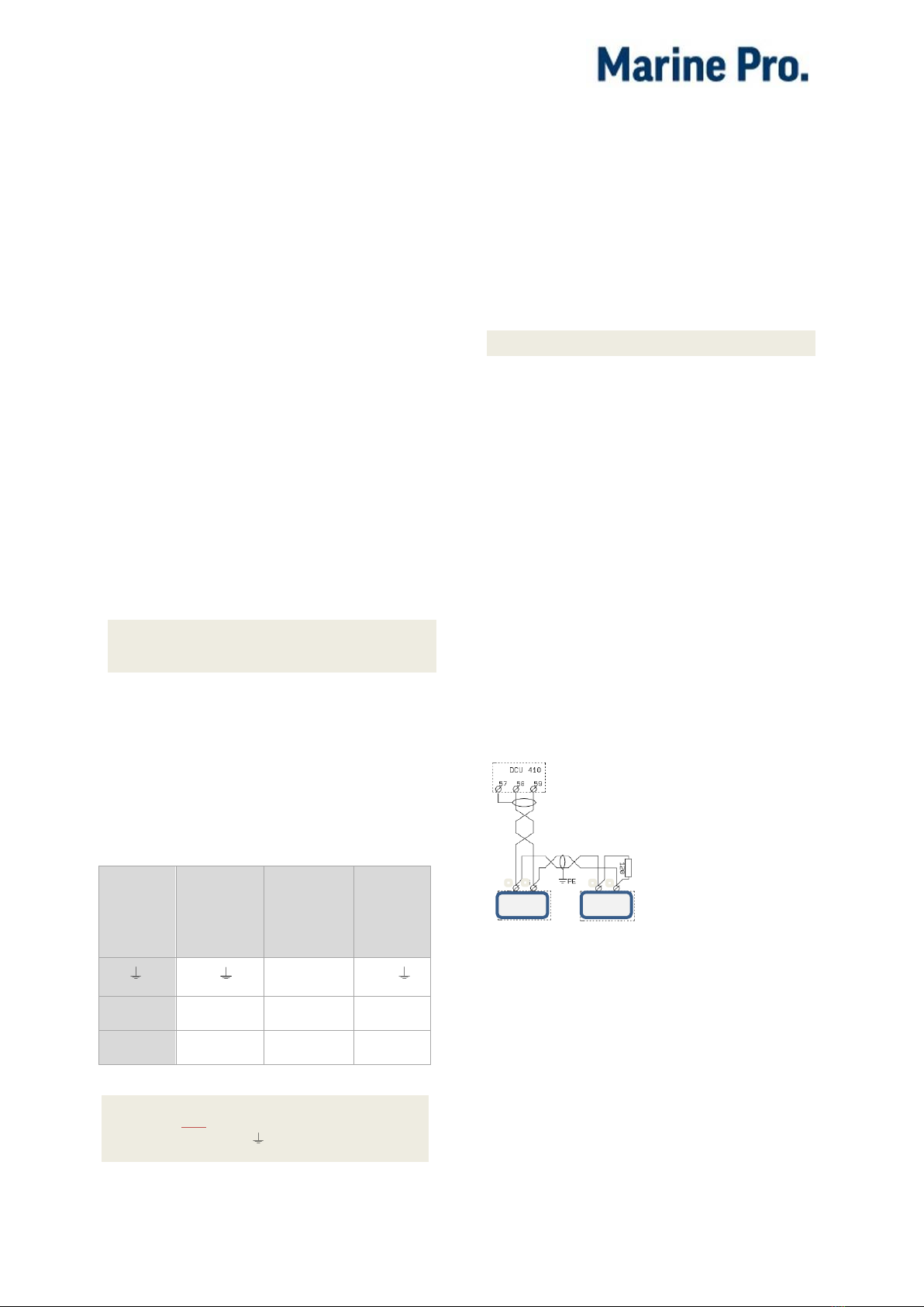
Communication Wiring
Depending on the DCU model connect
the wires in the shielded
communication cable to the terminals
as shown in the table below:
RIO
425
DCU
410(E)/
408(E)
DCU
210E/
208E
DCU
210/
208
S ( )
57 ( )
22 ( )
B (L)
58 (L)
C1-5 (L)
23 (L)
A (H)
59 (H)
C1-6 (H)
24 (H)
Note! Do not connect the
cable shield ( ) at both ends.
To minimize the effect of external
noise it is recommended to use
twisted pair wires.
Communication bus
termination resistor
Note! Do not skip this section!
The 120 ohm (1/4 W) termination
resistor shall be connected at the last
RIO unit (furthest away from the DCU)
in the RIO link chain.
If the RIO 425 is the only unit on the
RIO link, then the termination resistor
shall be connected at the RIO 425.
Connect the resistor directly across
terminals A and B on the RIO 425.
If the RIO 425 is
not
the last RIO unit
on the link, then the termination
resistor shall not be connected to the
RIO 425, but at the last RIO unit on the
RIO link.
If there are
several units
attached to the
link add the 120
Ohm resistor
together with
the last unit on
the bus.
The DCU has an inbuilt termination
resistor at its end.
When the bus is properly connected,
the measured impedance between bus
terminals A and B shall be 60 ohm
(+/- 5 ohm).

Page 4
Installation Manual - RIO 425
Is the DCU communicating
with the RIO 425?
This can be verified in the DCU web
server or user interface under the
Troubleshooting menu. See the RIO
425 section.
There is a comm LED indication on the
RIO 425 that flashes when
communicating.
Modbus Reference
To access the RIO 425 Modbus I/O list,
go to
200/400 Series Communication List
Modbus RTU Channel Specification
Parameter
Value
Physical
RS-485
Baud rate
19200
Start bits
1
Data bits
8
Stop bits
1
Parity
Even
Address
25
Generator Voltage
Interface
Connect the generator voltage
interface as follows:
Generator phase
RIO 425 terminal
N
13
L1
12
L2
11
L3
10
Wire requirement
Wires shall have a minimum area of
1.0 mm2(16 AWG).
Generator Current
Interface
Connect the generator current
interface as follows:
Phase
Current
transformer
RIO 425
terminal
L1
S1
S2
1
2
L2
S1
S2
3
4
L3
S1
S2
5
6
Wire requirement
The wire area shall be minimum 2.5
mm2(12 AWG).
Configuration
The RIO 425 can be configured from
the web server on a DCU in the Auto-
Maskin Marine Pro range. This is the
easiest and preferred method.
If no such DCU is available, the RIO
425 can be configured using the user
interface on the front of the unit.
Note! The current transformer ratio is
pre-configured to 5:1. It is possible to
change this ratio to 1:1, but only using
the RIO 425 user interface.

Installation Manual - RIO 425
Page 5
Configuration from the
DCU web server
Log into the DCU, and then select
Home and then RIO 425.
Set the desired values and press the
Submit button.
Configuration using the
user interface
The RIO 425 can be configured using
the small pushbuttons and display on
the front of the unit.
Initiate Configuration
To initiate the configuration, press and
hold the SETUP button for 5 seconds.
Voltage Transformer Primary
value
Note! This value shall conform to the
phase-phase voltage in the
installation. The setting is important
even if there is no voltage transformer
in the installation.
The display shows set PriU followed by
six digits; these allow the setting of
the transformer voltage primary value.
To write or change the voltage
transformer primary value, repeatedly
press the max key to increase the
value of the flashing digit.
When the required value is reached,
move on to the following digit by
pressing min.
When the last digit has been changed
or verified, press min to move back to
the first digit, allowing the previously
set values to be changed again.
To save the data and proceed, press
.
Voltage Transformer
Secondary value
Note! If there is no voltage transformer
in the installation, then the secondary
value shall be equal to the primary
value.
The display will show set SecU
followed by three digits; these allow
the setting of the secondary
transformer voltage.
To write or change the voltage
transformer secondary value,
repeatedly press the max key to
increase the value of the flashing digit.
When the required value is reached,
move on to the following digit by
pressing min.
When the last digit has been changed
or verified, press min to move back to
the first digit, allowing the previously
set values to be changed again.
To save the data and proceed, press
.

Page 6
Installation Manual - RIO 425
Current Transformer Primary
value
The current transformer primary value
should be as noted on the current
transformer(s) in use.
The display shows set PriA followed by
five digits; these allow the setting of
the current transformer primary value.
To write or change the current
transformer primary value, repeatedly
press the max key to increase the
value of the flashing digit.
When the required value is reached,
move on to the following digit by
pressing min.
When the last digit has been changed
or verified, press min to move back to
the first digit, allowing the previously
set values to be changed again.
To save the data and proceed, press
.
Current Transformer
Secondary value
Note! The RIO 425 comes preset to a
transformer ratio of 5:1, meaning the
secondary current varies up to 5A. If
necessary, the ratio can be changed to
1:1.
To select one of the two display
measurement options, press the max
key. The two available options will
toggle.
To save the new transformer ratio,
press .
Installation Manual - RIO 425
Page 7
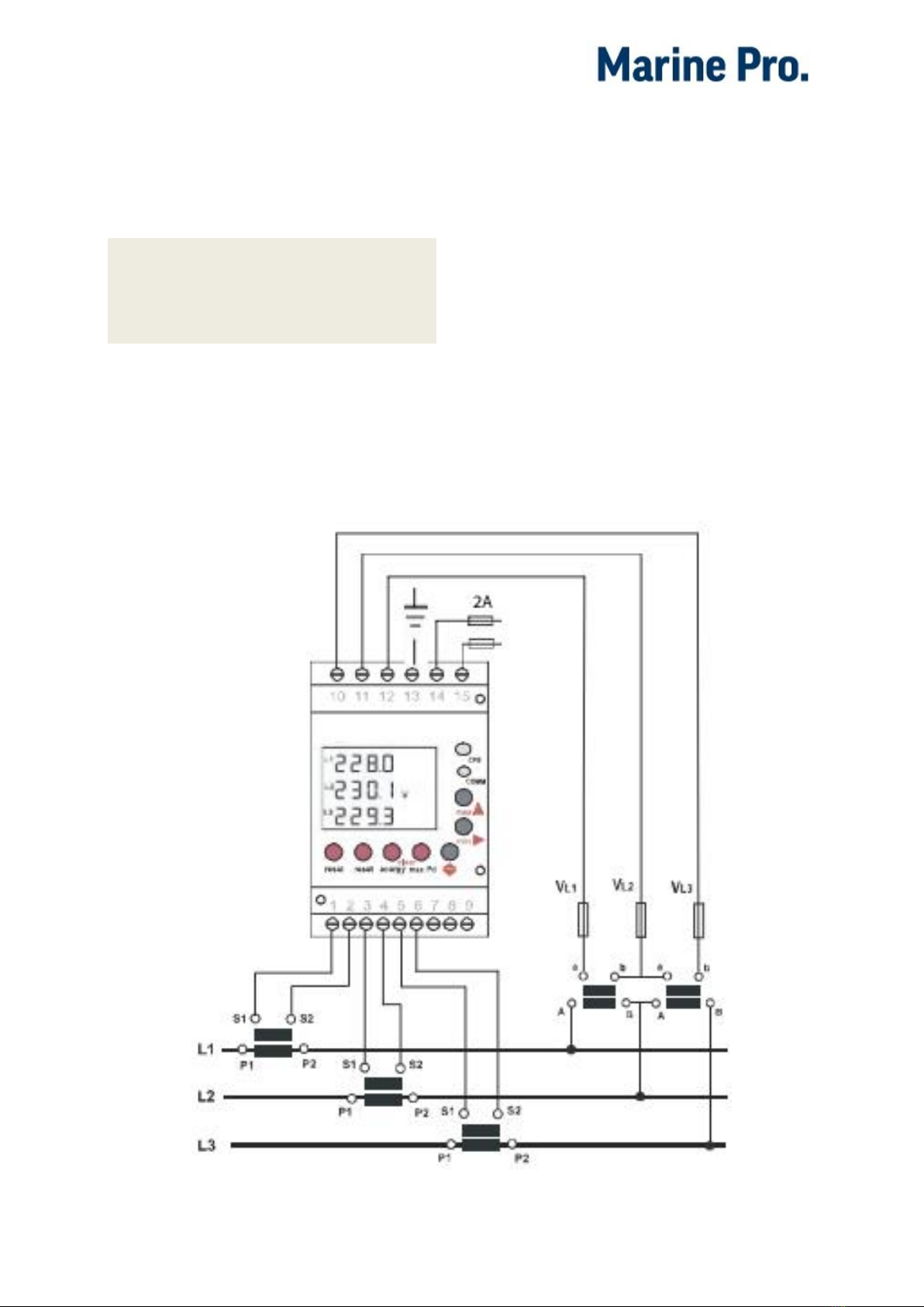
Schematic
This schematic shows a typical
installation of the RIO 425.
Note! The voltage transformer may or
may not be necessary. Consult the RIO
425 datasheet for supply voltage
range.
The RIO link communication interface
is not shown on the schematic.
The 3-pin communication interface
connector is on the underside of the
module.

Page 8
Installation Manual - RIO 425
Appendix
Setup RIO 425
communication
parameters
The RIO 425 comes ready configured.
If however, there is a need to verify the
parameters, then follow this
procedure.
Enter Communication setup
On the RIO 425, press the Reset
button, then immediately long-
press the Set-up button. The
display shall say Set Prot Bus.
Press the ⇕button to proceed.
Predefined communication
parameters
Next, the screen shall display Set Cdef
[yes/no].
Make sure to select Yes using
the ⇑ button.
Press ⇕ to proceed.
Peripheral number
Next, the screen shall display Set nPer
[0..255].
Make sure the value is set to
25, using the ⇑ and ⇒button.
Press ⇕ to proceed.
Transmission speed
Next, the screen shall display Set baud
[1200..19200].
Make sure the value is set to
19200, using the ⇑ button.
Press ⇕ to proceed.
Parity
Next, the screen displays Set Pari
[no/even/odd].
Make sure the value is set to
Even, using the ⇑ or button.
Press ⇕ to proceed.
Data bits
Next, the screen shall display Set Bits
[7/8].
Make sure the value is set to 8,
using the ⇑ button.
Press ⇕ to proceed.
Stop bits
Next, the screen shall display Set Stop
[1/2].
Make sure the value is set to 1,
using the ⇑ button.
Press ⇕ to proceed.
Press ⇕ again to save and quit.
Table of contents
Other auto maskin Recording Equipment manuals


