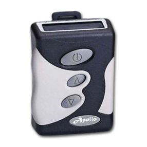
Auto Page AP4000EX User manual

1
OPERATING INSTRUCTIONS
INSTALLED AS A STAND-ALONE SYSTEM
INSTALLED WITH AN AUDIBLE ALARM SYSTEM
CHANGING THE BATTERY
INSTALLATION INSTRUCTIONS
BEFORE INSTALLATION
CONTENTS
WIRE HARNESS CONNECTIONS
ANTENNA CONNECTION
INSTALLING AS A STAND-ALONE SYSTEM
INSTALLING WITH AN ALARM SYSTEM
CODING THE PAGER(S)
ON/OFF SWITCH SETTINGS
LED & TONE IDENTIFICATION
PAGER MEMORY
USING THE CALL BUTTON
RANGE
ORDERING ADDITIONAL PAGERS AND TRANSMITTERS
AUTOPAGE ACCESSORIES
WIRING DIAGRAM
WARRANTY PROVISIONS

2
OPERATING INSTRUCTIONS
IF INSTALLED AS A “STAND-ALONE” SYSTEM
1. Exit the vehicle in the normal manner.
2. Approximately 10 seconds after leaving the vehicle switch on the pager to its audible or vibrator mode. Once
switched on, the pager will begin to beep or vibrate.(*) In approximately 2 seconds, the pager will automatically reset
itself in the stand-by mode. It is now ready to receive a signal from the vehicle should vehicle security be breached.
(*) See SWITCH SETTINGS section in this manual for switch positions.
3. If vehicle security is breached, or if you wish to test the pager, open a vehicle door. The pager will begin to beep or
vibrate after approximately 3 seconds. (*)
NOTE: When a trigger is received the pager will vibrate or sound for approximately 7 seconds. It will then
automatically reset, and the trigger will be stored in memory.
(*) See CODING THE PAGER section in the installation portion of this manual for information regarding the pager
LED’s, pager tones and their functions, using the call button, pager memory, and pager ON/OFF switch settings.
IF INSTALLED WITH AN AUDIBLE ALARM SYSTEM
1. Exit vehicle and arm the alarm as normal. The AP4000EX will automatically arm as soon as the audible alarm is
armed.
2. Test the pager by triggering the alarm system. The pager will begin beeping, or vibrating 3 seconds after the siren has
started sounding. (*) Allow 10 seconds to lapse before resetting the pager. Rearm the alarm system and test again if
required.
NOTE: When a trigger is received the pager will vibrate or sound for approximately 7 seconds. It will then
automatically reset, and the trigger will be stored in memory.
(*) See CODING THE PAGER section in the installation portion of this manual for information regarding the pager
LED’s, pager tones and their functions, using the call button, pager memory, and pager ON/OFF switch settings..
NOTE 1: If the AP4000EX has been installed with a relay to actuate the vehicle’s fully automatic power antenna, a
slight rise and fall of the power antenna may be noticed each time the alarm is armed or disarmed, or each time the door
is opened and closed if the AP4000EX has been installed as a stand-alone system. This action should be considered
normal due to certain installations and circumstances.
NOTE 2: Proper operation of the pager depends greatly upon the installation methods as well as where the vehicle may
be parked. Within a city or suburban environment, reception from one half (1/2) to three quarters (3/4) of a mile is
considered normal. However, this will vary depending on what the signal must travel through. The pager signal can be
weakened by heavy concrete structures, other more powerful radio or electronic signals, and will be completely

3
stopped by metal. Additionally, improper or inadequate antenna connections will result in poor pager range and
reception, and will also damage the main pager unit’s electronics. Such damage will not be covered under the warranty.
CHANGING THE PAGER BATTERY
The AP4000EX pager uses one (1) AA-Alkaline battery. For proper operation this battery should be changed
approximately every 20 days with the same quality battery. SUBSTITUTIONS ARE NOT RECOMMENDED.
Too change the pager battery, gently push the battery cover down and slide it off. Insert the new battery (note polarity),
and close the battery cover. Turn the pager on to test the new battery.
NOTE: The AP4000EX pager is equipped with a low battery warning. When in its stand-by mode the pager will emit
2 short beeps every second to signal that its battery needs to be replaced. THE PAGER WILL NOT RECEIVE ANY
SIGNALS WHEN THE LOW BATTERY WARNING IS ACTIVE.
NOTE: When the pager is not in use, it is recommended that it be turned off to conserve battery life.
WARNING: DO NOT ALLOW THE PAGER TO BE EXPOSED TO MOISTURE. IT IS NOT WATERPROOF.
WARNING: DO NOT DROP THE PAGER. REPEATED DROPPING WILL DAMAGE THE PAGER
Either of the above will not be covered under the warranty. For full warranty details, consult the warranty at the back of
this manual.

4
INSTALLATION INSTRUCTIONS
BEFORE INSTALLATION
BEFORE BEGINNING THE INSTALLATION, THOROUGHLY READ OVER THIS MANUAL TO BECOME
FAMILIAR WITH ALL OF THE INSTALLATION STEPS.
SUGGESTED INSTALLATION EQUIPMENT
[ ] Electric, and/or battery operated drill.
[ ] Assorted drill bits
[ ] Phillips and straight blade screwdrivers.
[ ] Needlenose pliers.
[ ] Diagonal cutters.
[ ] Wire cutter/stripper.
[ ] Wire connector crimping tool.
[ ] Soldering iron, or gun.
[ ] Voltmeter. (SEE CAUTIONS BELOW)
SUGGESTED INSTALLATION SUPPLIES
[ ] One NEW “AA” cell alkaline battery. (*)
[ ] Assorted, insulated lug and splice connectors.
[ ] Vinyl electrical tape.
[ ] Plastic tie wraps. (Cable ties)
[ ] Plastic shrink wrap and protective tubing.
[ ] Electrical diagram for the vehicle you are working on.
[ ] Solder approved for automotive use.
(*) The battery packed with the AP4000EX is a “test only” battery. This battery should be replaced with a new battery
as AutoPage cannot guarantee maximum voltage.
IT IS STRONGLY RECOMMENDED THAT A VOLTMETER BE USED FOR CHECKING ALL ELECTRICAL
CIRCUITS IN THE VEHICLE, INSTEAD OF A COMMON TEST LIGHT! Test lights can cause vehicle computer
damage if the wrong wires are probed, and can cause air bag systems to activate (deploy). Either of the above will
cause extensive damage to the vehicle, resulting in costly repairs. Pay close attention to all caution labels in the vehicle.
AutoPage will assume absolutely no responsibility whatsoever for this, or any other damage done to the vehicle, or any
personal injury due to improper installation. Refer to the limited warranty for details.
A suitable place must be located to permanently install the AP4000EX main control unit. This should be an area that is
not exposed to excessive temperatures or moisture. DO NOT INSTALL THE CONTROL UNIT UNDER THE
HOOD OF THE VEHICLE! IT IS NOT WATERPROOF. WATER DAMAGE WILL NOT BE COVERED
UNDER THE WARRANTY.

5
If the AP4000EX is to be connected through the vehicle’s fully automatic power antenna, it will be necessary to locate
the wire from the vehicle radio to the power antenna relay which signals the antenna to raise or lower. This wire will
show voltage each time the radio is switched “on”, allowing the antenna to raise. When the radio is switched “off”,
voltage will be eliminated and the antenna will lower.
At this time, determine a switched ignition source from the vehicle, and if installing with an alarm system, determine if the
alarm system triggers positive or negative if the alarm does not have a separate pager trigger output.
After performing the above tests, DISCONNECT THE MAIN BATTERY POWER OF THE VEHICLE!
WARNING! DO NOT INSTALL THE AP4000EX TRANSMITTER OR ITS ANTENNA NEXT TO ANY
VEHICLE’S COMPUTER, NOR ANY AUDIO SYSTEM COMPONENT THAT USES A SWITCHING
POWER SUPPLY. The radio frequency energy from the transmitter may cause interruption or improper operation of
such devices. AutoPage does not accept any liability for any losses or damage, whatsoever, resulting from such
operation.
CONTENTS
AP4000EX main control unit = 1
AP4000EX paging receiver = 1
6 wire harness = 1
2 wire harness = 1
Call button = 1
Radio cable (coax) jumper = 1
Warning decal = 2
Installation/User manual = 1
WIRE HARNESS CONNECTIONS & WIRE IDENTIFICATION
2 Wire Harness
1. RED w/fuse connector = Main power supply.
2. BLACK = Main system ground.
6 Wire Harness
1. WHITE = Switched ignition input.
2. GRAY = Negative trigger input.
3. VIOLET = Positive trigger input.
4. YELLOW = Fully automatic antenna output control. (*)
5. PINK = Optional shock sensor input.
6. GREEN = Call button input.
(*) Requires optional relay. See cautions in this manual regarding connection of this output.
WARNING: INSTALL THE SYSTEM WIRING SO THAT POWER CONNECTIONS ARE MADE AFTER
THE ANTENNA AND ALL OTHER CONNECTIONS HAVE BEEN MADE. REPEATED TRIGGERING OF

6
THE AP4000EX WITHOUT AN ANTENNA WILL RESULT IN DAMAGE TO THE TRANSMITTER
PORTION OF THE SYSTEM. SUCH DAMAGE WILL NOT BE COVERED UNDER THE WARRANTY.
ANTENNA CONNECTION
1. If the existing car radio antenna is used, disconnect the vehicle’s radio antenna cable from the radio. Plug the vehicle
antenna into the terminal of the AP4000EX main unit marked CAR ANTENNA. Plug the supplied coax jumper cable
into the terminal of the AP4000EX marked CAR RADIO. Plug the remaining end of the coax jumper into the vehicle’s
radio.
2. If the vehicle is equipped with a fully automatic power radio antenna and you wish to use this antenna for the
AP4000EX, and optional relay must be used to automatically raise and lower the antenna during the paging cycle.
ANTENNA
CAR RADIO
YELLOW (ANTENNA ACTUATOR CONTROL)
CUT
12 VOLTS CONSTANT
VEHICLE
ANTENNA
RELAY
OPTIONAL
RK-1 RELAY
VEHICLE FULLY AUTOMATIC
POWER ANTENNA. (SEE NOTE #1 BELOW)
SUPPLIED
COAX
JUMPER
VEHICLE RADIO
[FIGURE 3]
CAUTION: DO NOT ATTEMPT TO CONNECT
MORE THAN ONE ANTENNA TO THE
TRANSMITTER.
NOTE #1 THIS ANTENNA MUST BE FULLY
AUTOMATIC FOR PROPER OPERATION.
READ THE MANUAL FOR OTHER WARNINGS
AND CAUTIONS.

7
NOTE: Semi-automatic power antennas which must be raised and lowered by a switch will not work with the above
method. Such antennas must be left in the raised position for proper pager output, or a separate antenna must be
dedicated to the AP4000EX.
3. If installing the AP4000EX with the AutoPage TW-5 glass mount antenna, or TW-2, it is suggested that the
AP4000EX be mounted in the trunk of the vehicle. A constant source of 12 volts must be supplied to operate the
pager. In addition, a switched ignition wire from the vehicle, as well as the pager trigger wire must be routed to the
trunk. If the pager is installed as a stand-alone system, this installation method is highly recommended so that it will not
be necessary to route the antenna coax cable through the vehicle. Routing the coax cable of the antenna through the
vehicle may cause RF interference during the paging cycle if installed with an alarm.
ANTENNA
CAR RADIO
OPTIONAL
TW-5 GLASS
MOUNT
ANTENNA.
(SEE NOTE
#2 BELOW)
OPTIONAL
TW-2
ANTENNA
(SEE NOTE
#2 BELOW)
TO ANTENNA INPUT TERMINAL
ON PAGER MAIN CONTROL
WHEN VEHICLE RADIO ANTENNA
IS NOT USED.
[FIGURE 4]
CAUTION: DO NOT ATTEMPT TO CONNECT MORE THAN ONE
ANTENNA TO THE TRANSMITTER.
WARNING: IF THE VEHICLE’S EXISTING ANTENNA CONTAINS AN AMPLIFIER IN THE ANTENNA’S
BASE OR ANYWHERE IN ITS COAX CABLE, OR IF THE ANTENNA IS COMPUTER CONTROLLED,
MAKE NO ATTEMPT TO CONNECT THAT ANTENNA TO THE AP4000EX. THE ANTENNA AMPLIFIER
AND/OR COMPUTER CONTROL WILL BE DAMAGED. DO NOT CONNECT THE AP4000EX TO ANY
“IN-THE-GLASS” ANTENNA. IN THE EVENT OF SUCH STYLE ANTENNAS, IT WILL BE NECESSARY
TO DEDICATE AN ANTENNA TO THE PAGER FOR ITS EXCLUSIVE USE. USE THE AUTOPAGE TW-5,
OR TW-2, OR A GOOD QUALITY CB ANTENNA. DO NOT CONNECT THE AP4000EX TO ANY
CELLULAR TELEPHONE ANTENNA. IF YOU DO NOT KNOW WHAT TYPE ANTENNA THE VEHICLE

8
USES, CALL THE AUTOPAGE TECHNICAL DEPARTMENT AT 800/262-2526, EXTENSION 451 FROM
7:30 AM TO 5:00 PM PST. FAILURE TO FOLLOW THE ABOVE WARNINGS WILL CAUSE DAMAGE TO
THE VEHICLE AND THE PAGER MAIN UNIT, AND WILL NOT BE COVERED UNDER THE WARRANTY.
INSTALLING AS A STAND-ALONE SYSTEM
1. AFTER you have determined the location of a constant battery source for connection of the AP4000EX control unit,
you must also determine a source of switched 12 volts from the ignition switch. This source, usually found in the ignition
switch harness, will show constant voltage when the key is “ON” and the engine is running. This voltage source must be
eliminated when the engine is switched “OFF”. WARNING: DO NOT DISREGARD THIS STEP! CONNECTION
OF THE VEHICLE’S SWITCHED IGNITION TO THE WHITE WIRE OF THE AP4000EX IS VERY
IMPORTANT. THIS CONNECTION WILL TURN OFF THE AP4000EX SO IT WILL NOT BE ALLOWED
TO TRANSMIT A SIGNAL DURING VEHICLE OPERATION.
2. After securing the main control unit (*), connect the SWITCHED IGNITION as determined in the above step to the
WHITE ignition input wire.
(*) DO NOT SECURE THE PAGER MAIN CONTROL UNIT TO ANY AIR BAG RELATED WIRE HARNESS
OR COMPONENT.
3. When installed as a stand-alone system, triggering of the AP4000EX will be from the vehicle’s pin switch (dome
light) circuit. Connect in the following manner. For POSITIVE switched vehicles (most Fords), connect a wire from
the switched side of the vehicle’s pin switch to the VIOLET input wire of the AP4000EX. For NEGATIVE switched
vehicles, (most, except Fords) (*), connect a wire from the switched side of the vehicle’s pin switch to the GRAY input
wire of the AP4000EX.
(*) Some late model Ford vehicles now use a NEGATIVE pin switch system. Check carefully before making the
connection.
OFF START
RUN
ACCESSORY
BATTERY
WHITE
(SWITCHED IGNITION INPUT)
[FIGURE 5]
IGNITION SWITCH

9
GRAY TRIGGER
INPUT WIRE
PURPLE TRIGGER
INPUT WIRE
SWITCH BODY
GROUNDED TO VEHICLE
SWITCH BODY
ISOLATED FROM VEHICLE 12 VOLT CONSTANT
SUPPLY FROM VEHICLE
TO INTERIOR LIGHTS
TO INTERIOR LIGHTS
NEGATIVE SWITCHING
POSITIVE SWITCHING
(MOST FORDS)
[FIGURE 6]
4. The PINK wire is provided for the installation of optional AutoPage sensors for added security. Install and adjust the
chosen sensor according to the sensor’s installation instructions.
5. Select a suitable location and install the CALL (*) button. Connect the GREEN wire
from the AP4000EX 6 wire harness to one side of the call button. Connect the remaining
wire from the call button to vehicle ground.
(*) Do not eliminate the CALL button. It must be used to program the pager.
6. Connect the BLACK main ground wire to a solid ground as close to the control unit as possible. Keep the ground
wire as short as possible.
CALL SWITCH
(MOMENTARY SWITCH) GREEN

10
7. Connect the RED fused main power supply wire to a constant source of direct battery voltage.
INSTALLING WITH AN ALARM SYSTEM
If the AP4000EX is being installed as an add-on with an audible alarm system, connect as follows.
1. If the alarm has a separate pager trigger output, connect to the proper polarity trigger input of the AP4000EX.
2. If the alarm does not have a separate pager trigger output, the alarm siren may be used to trigger the pager. If the
alarm triggers POSITIVE as determined at the start of the installation, connect a “tap-off” wire from the siren lead.
Connect the “tap-off” to the VIOLET wire from the AP4000EX. If the alarm triggers NEGATIVE as determined at
the start of the installation, connect a “tap-off” wire from the siren lead. Connect the “tap-off” to the GRAY wire from
the AP4000EX.
3. Select a suitable location and install the CALL (*) button. Connect the GREEN wire
from the AP4000EX 6 wire harness to one side of the call button. Connect the remaining wire from the call button to
vehicle ground.
(*) Do not eliminate the call button. It must be used to program the pager.
4. Connect the BLACK main ground wire to a sold ground as close to the pager control unit as possible. Keep this
wire as short as possible.
5. Connect the RED fused main power supply wire to a constant source of direct battery voltage.
6. Connect the vehicle’s switched ignition source to the WHITE wire from the pager 6 wire harness. Refer to item 1 of
INSTALLING AS A STAND-ALONE SYSTEM for procedure and warnings.
7. No other connections should be made.
CODING THE PAGER(S), ON/OFF SWITCH SETTINGS, LED & TONE IDENTIFICATION, PAGER
MEMORY, CALL BUTTON
The AP4000EX pager is capable of monitoring three vehicles with optionally installed AP4000EX paging transmitters.
Additionally, the pager will hold the last trigger in memory.
1. Reconnect the battery in the vehicle.
2. Open the battery compartment on the pager and place a fresh “AA” cell into the battery compartment. Alkaline is
recommended for best performance. Be certain the battery polarity is correct. Replace the battery cover.
NOTE: The AP4000EX pager is equipped with a low battery warning. When in its stand-by mode the pager will emit
2 short beeps every second to signal that its battery needs to be replaced. THE PAGER WILL NOT RECEIVE ANY
SIGNALS WHEN THE LOW BATTERY WARNING IS ACTIVE.

11
CODING THE PAGER
Each AP4000EX pager is capable of learning up to three codes to monitor the original vehicle installation and optional
paging receivers installed in two other vehicles.
Step 1. Vehicle ignition must be OFF.
Step 2. Press and hold the reset switch on the pager, then turn its power switch ON. When the beeping stops, release
the reset switch.
Step 3. The RED LED will begin flashing. Within 5 seconds, press the reset switch 1 time. (*) The GREEN LED will
glow solid (**). Within 15 seconds, push the CALL button (***). The LED will turn off and the pager will chirp 2
times. Code learning is now complete.
NOTE (*) To code the pager for vehicle #2, press the reset switch 2 times. To code the pager for vehicle #3, press the
reset switch 3 times.
NOTE (**): If the 5 second time period is allowed to lapse after the RED LED begins to flash, the pager will
automatically return to its stand-by mode. If this happens, it will be necessary to start the code learning process again.
NOTE (***): The CALL button must be pushed with 15 seconds after the GREEN LED begins to glow. If the 15
second time period is allowed to lapse the pager will automatically return to its stand-by mode. If this happens, it will be
necessary to start the code learning process again.
THE CODE LEARNING MODE MUST BE ENTERED EACH TIME IF THE PAGER
IS TO BE PROGRAMMED INTO ADDITIONAL VEHICLES.
4. Turn on the pager. It will begin beeping and vibrating for approximately three (3) seconds. It will then automatically
reset itself in its receiving mode.
5. Test the pager with the vehicle’s ignition switch off. If installed as a stand-alone system open the door on the vehicle,
or trigger any optionally installed sensor. In approximately three (3) seconds the pager will respond with a continuous
beeping sound, or continuous vibrating. Additionally, the LED inside the pager will blink in accordance to the particular
trigger.
ON/OFF SWITCH SETTINGS
Position 1 = OFF
Position 2 = Vibration alert
Position 3 = Tone and LED alert

12
LED & TONE IDENTIFICATION
1. Zone LED
RED/GREEN alternate flashing LED with 2 short beeps = Vehicle security has been breached.
RED flashing LED with 1 long beep = Added sensor or sensors have been triggered,
GREEN flashing LED with phone type ring = Pager call button has been activated.
2. Identification LED
RED flashing LED = Trigger alert from vehicle #2 (*)
GREEN flashing LED = Trigger alert from vehicle #3 (*)
(*) Requires optional paging transmitters in each vehicle.
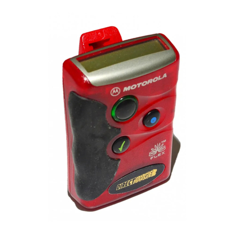
(INSERT PICTURE OF PAGER SHOWING LOCATION OF LED’S, ON/OFF SWITCH, AND RESET
SWITCH)
PAGER MEMORY
The AP4000DX pager will recall the last trigger or call input signal in its memory while
in the stand-by mode. To recall the memory, press the reset button. The LED will flash as noted above in the LED and
tone identification section. If in the vibration mode, the pager will vibrate every 30 seconds to indicate it has received a
trigger or call signal. If in the tone mode, the pager will beep 1 time every 30 seconds to indicate that it has received a
trigger or call signal.
NOTE: Turning the pager off will automatically clear the memory.
USING THE CALL BUTTON
The driver of the vehicle may wish to send a call signal to a passenger outside the vehicle who is carrying the pager. To
send a call signal, press the call button located in the vehicle.
NOTE: The call button will function with the vehicle ignition on or off.

13
RANGE
The range of the AP4000EX will vary according to numerous factors. Among them are vehicle location, location and
distance of user to vehicle, antenna placement, environmental conditions, and electronic signals or frequencies which
may block or break up the signal from the pager. Normal range within a city or suburban environment is approximately
one half (1/2) to three quarters (3/4) of a mile, by line of sight. Under absolute ideal conditions, ranges of two to three
miles are not uncommon.
WARNING! UNDER NO CIRCUMSTANCES SHOULD ANY ATTEMPT BE MADE TO BOOST OR
AMPLIFY THE SIGNAL FROM THE AP4000EX. SUCH ACTIONS ARE IN DIRECT VIOLATION OFF FCC
RULES AND REGULATIONS.
ORDERING ADDITIONAL PAGERS AND TRANSMITTERS
AP4000EX ACCESSORIES
PG-21 -Additional or replacement pager/receiver.
TX4000E -Additional paging transmitter for second and third vehicle installation. (Includes necessary wire harnesses
and coax jumper.)
TW-2 -Rubber ducky antenna.
TW-5 -Glass mount cellular style antenna.
RK-1 -Prewired relay kit.
SIS-3 -Electronic impact sensor.
SIS-10 -Super low frequency air vibration sensor.

14
GRAY (NEGATIVE TRIGGER INPUT)
PURPLE (POSITIVE TRIGGER INPUT)
PINK (OPTIONAL SENSOR INPUT)
WHITE (SWITCHED IGNITION INPUT)
YELLOW (ANTENNA ACTUATOR CONTROL)
VEHICLE FULLY AUTOMATIC
POWER ANTENNA. (SEE NOTE #1 BELOW)
OPTIONAL
TW-5 GLASS
MOUNT
ANTENNA.
(SEE NOTE
#2 BELOW)
OPTIONAL
TW-2
ANTENNA
(SEE NOTE
#2 BELOW) BLACK (VEHICLE GROUND)
RED (TO CONSTANT 12 VOLTS)
CAUTION: DO NOT CONNECT
POWER UNTIL AN ANTENNA
HAS BEEN CONNECTED.
GREEN (CALL MOMENTARY SWITCH)

15
LIMITED LIFETIME WARRANTY PROVISIONS
(U.S. and Continental U.S. Only)
1.AutoPage, Inc. WARRANTS that this new unit has been thoroughly inspected and
tested at the factory prior to delivery. Your AutoPage equipment is Guaranteed for
"life" to the original purchaser/user of the equipment under the following conditions:
If the product proves defective (according to AutoPage's testing) within the first
year, the defective unit may be exchanged or repaired free of charge. "Proof of
Purchase" (dated sales receipt) must accompany all warranty returns; otherwise,
your returns will be rejected and sent back.After one (1) year, the
purchaser should ship the unit pre-paid to AutoPage with a money order in the
amount of $20.00 to cover handling and shipping charges. Note: The WARRANTY
CARD on the back of this page may be required to receive warranty services.
2. This WARRANTY will be considered VOID if the equipment has been misused,
neglected, improperly serviced, altered, dropped or damaged by water, contrary to
the AutoPage INSTRUCTION MANUAL. Or, if used with accessories not approved
by AutoPage, which may have contributed to the defect.
3. The purchaser's remedies under this WARRANTY shall be limited to the repair or
replacement of electronic components only.
THE FOLLOWING IS NOT COVERED: Damages or deterioration to cases, batteries,
covers and cabinets; the cost of repairs, replacement and labor of which shall be
borne by the purchaser even if occurring during the WARRANTY period.
4. Any equipment or parts which are claimed to be defective under this
WARRANTY must be sent to the AutoPage Service center with "proof of purchase"
at purchaser's expense prior to such return, a Return Authorization Number should
be obtained. AutoPage will return the equipment, charges prepaid. Warranty
Service can be provided through the dealer where the equipment is originally
purchased.
5. Any unexpired WARRANTY shall be applicable to equipment and parts in the
possession of the original purchaser only.
6. THIS WARRANTY IS IN LIEU OF ANY AND ALL OTHER WARRANTIES,
EXPRESSED OR IMPLIED, INCLUDING BUT NOT LIMITED TO ANY WARRANTY OF
MERCHANTABILITY OR FITNESS FOR A PARTICULAR PURPOSE.
7 AutoPage shall not be liable, under the foregoing WARRANTIES or otherwise,
for: Any personal injury of any kind to the purchaser, its employees or agents or
anyone else whomsoever resulting directly or indirectly from the use or presence
of the equipment or parts; Consequential damages of any kind; Any inability of the
purchaser to use the equipment.

16
This WARRANTY CARD is for your record. However, AutoPage reserves the right to request
you to submit this WARRANTY CARD which must have complete information to receive
warranty service. Please keep this card in a secured place.
AUTOPAGE WARRANTY SERVICE CARD
Model__AP-4000EX______Serial#___________________________
CUSTOMER TO COMPLETE DEALER TO COMPLETE
Mr/Mrs/Ms
__________________________ _________________________
Your Name (Please print) Company Name
__________________________ _________________________
Address Address
__________________________ _________________________
Telephone Number City, State, Zip
__________________________ _________________________
Year/Make/Model of Vehicle Dealer's Telephone Number
_________________________
Date of Installation\Purchase
"Proof of purchase" which includes the store name and date of purchase must
accompany all warranted returns.
It is your responsibility to keep this card for any future warranty service.
AutoPage
Service Center
1815 W. 205th St., #101
Torrance, Ca. 90501
Tel:(310) 618-2002

17
Other manuals for AP4000EX
1
Table of contents
