manuals.online logo
Brands
  1. Home
  2. •
  3. Brands
  4. •
  5. AutoAqua
  6. •
  7. Accessories
  8. •
  9. AutoAqua Smart AWC Duo User manual

AutoAqua Smart AWC Duo User manual

Smart AWC Duo
SAWC-400P
Change for Simple
Smart AWC Duo
Controller x1
1. Controller with touch
panel & two Dual Sensors
2. Max. Mounting Thickness :
1/2 inch (12.7 mm)
Head : 8.2 feet (250 cm)
DC Pump x3
Universal Power
Adapter x1
Universal Power Supply :
100-240 VAC
A connector to break
the siphon
Siphon Break x3
For rimmed and rimless
aquariums up to 1/2 inch
(12.7 mm)
Universal Tube
Holder x3
Picture
Item
List of Parts (Can Be Purchased Separately)
Tubing 19.6 feet
(600 cm) Used with DC Pumps
Change for Simple
Description
1
Caution:RiskofInjuryfromStrongMagnets
Controller & Dual Sensors
Change for Simple
2
Smart AWC Duo Controller
High Level ATO/AWC Sensor*
High Level Failsafe Sensor
High Level Dual Sensor
Low Level Failsafe Sensor
Low Level AWC Sensor*
Low Level Dual Sensor
*The High Level ATO/AWC Sensor must be at least 1/4 inch
(6 mm) higher than the Low Level AWC Sensor, or Smart AWC
Duo will not work properly.
: High Level Dual Sensor
: Low Level Dual Sensor
: Power DC Jack
: ATO Filling Pump/ Freshwater AWC
Filling Pump Jack
: AWC Drain Pump Jack
: Saltwater AWC Filling Pump Jack
Installation
Change for Simple
3
*Please avoid setting up the sensor in an area with micro bubbles
or direct light.
Step 1 :
Mount the blue sensor
( ) at normal water level S1
– ATO water level (with
the lower sensor
indicating the water
level) on the tank/sump
with the magnet.*
1. AWC
(Auto Water Change)
i. Saltwater Aquarium
Tank/Sump
WaterChangeVolume
AWCDrainPump
WasteWater
WasteWaterContainer Tank/Sump
Step 4 :
Connect AWC
drain pump to
P2.
Step 2 :
Mount the green sensor
( ) at low water level S2
(with the top sensor
indicating the water
level) on the tank/sump
with the magnet.*
Arrow on siphon break
indicates water ow direction.
Air In
Water Out
*Note : Place siphon break inside the tank/sump but above the
water level.
Siphon break allows air in to break the siphon when the Air In :
pump turns off.
Water drops out of the hole are normal when the pump is on. Water Out :
Step 3 :
Connect AWC drain
tube(pump siphon
break* tubing holder).
Change for Simple
4
AWCFillingPump
Power
WasteWater
Tank/Sump
WasteWaterContainer NewWaterReservoir
AWCDrainPump
*Please avoid setting up the sensor in an area with micro bubbles
or direct light.
Step 1 :
Mount the blue sensor
( ) at normal water level S1
– ATO water level (with
the lower sensor
indicating the water
level) on the tank/sump
with the magnet.*
ii. Freshwater Aquarium
For Freshwater aquariums, P3 is not required.
Tank/Sump
WaterChangeVolume
Step 2 :
Mount the green sensor
( ) at low water level S2
(with the top sensor
indicating the water
level) on the tank/sump
with the magnet.*
Step 7 :
Connect power adapter. Step 6 :
Connect AWC lling pump to P3.
Step 5 :
Connect AWC lling
tube ( pump siphon
break tubing holder).
Change for Simple
5
Power
AWCFillingPump
Tank/Sump WasteWaterContainer
AWCDrainPump
AWCFillingPump
NewWaterReservoir Tank/Sump
Step 4 :
Connect AWC lling
pump to P1.
NewWaterReservoir
Step 7 :
Connect power adapter. Step 6 :
Connect AWC drain pump to P2.
Air In
Water Out
*Note : Place siphon break inside the tank/sump but above the
water level.
Siphon break allows air in to break the siphon when the Air In :
pump turns off.
Water drops out of the hole are normal when the pump is on. Water Out :
Arrow on siphon break
indicates water ow direction.
Step 3 :
Connect AWC lling
tube ( pump siphon
break* tubing holder).
Step 5 :
Connect AWC drain
tube ( pump siphon
break* tubing holder).
Change for Simple
6
*Please avoid setting up the sensor in an area with micro bubbles
or direct light.
2. ATO (Auto Top Off)
Step 1 :
Mount the blue sensor
( ) at normal water level S1
(with the lower sensor
indicating the water
level) on the tank/sump
with the magnet.*
Tank/Sump
ATOFillingPump
ATOReservoirTank/Sump
Step 3 :
Connect ATO
lling pump
to P1.
Arrow on siphon break
indicates water ow direction.
Air In
Water Out
*Note : Place siphon break inside the tank/sump but above the
water level.
Siphon break allows air in to break the siphon when the Air In :
pump turns off.
Water drops out of the hole are normal when the pump is on. Water Out :
Step 2 :
Connect ATO lling tube
( pump siphon break*
tubing holder).
In freshwater mode,
ATO operates with pump 1.
Change for Simple
7
ATOFillingPump
ATOReservoir
Step 4 :
Connect power adapter.
Tank/Sump
Power
ACSwitch
Tank/Sump
OpticalLevelSensor
Reservoir
ACFillingPump AC
Power
*The DC pumps can be replaced with larger AC pumps with
AUTOAQUA Smart AC Switch
Calculating the Water Change Volume
Change for Simple
8
The volume can be calculated by multiplying the width and length
of your tank and the distance between the pyramids of the two
sensors.*
For example, a tank is 18 inches in length and 17 inches in width. If
the distance between the two sensors is 3 inches, the water change
volume is approximately 4 gallons.

18” (L) X 17” (W) X 3” (H) = 918 cubic inches (around 4 gallons)**
* The water volume might be inuenced by factors such as the
speed of return pump.
**231 cubic inches = 1 US gallon
Length:18”
Width:17”
WaterChangeVolume Height:3”
*During water change process, pressing can stop the process
and return to the previous AWC MANUAL/AUTO setting page. Also,
ATO is forced to be turned off if its previous status is on and at the
same time the controller gives a ve-second audible and visual alert
( ashing).
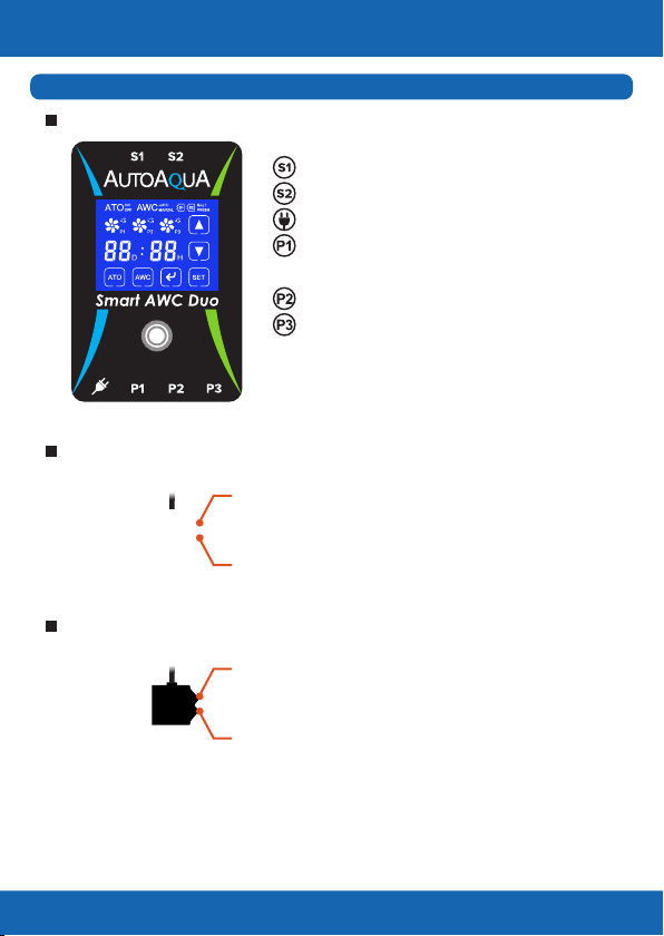
Icons & Buttons for Setting
Change for Simple
9
1Turn ATO on or off
1 2 3 4
5
6
2Choose AWC MANUAL / AUTO mode or
turn AWC off
1. Start / pause / resume the AWC process
2. Dismiss alarm
3
Choose the setting item in the AWC MANUAL /
AUTO mode
4
1. Increase day / hour
2. Choose Saltwater / Freshwater mode
5
1. Decrease day / hour
2. Choose Saltwater / Freshwater mode
6
1. Wake up the display
2. Dismiss alarm
3. Resume AWC process
4. Return to AWC setting page*
5. Reset (hold at least for 8 seconds until the
display goes black)
7
No.
7
Display Indication
Change for Simple
10
12 3
4
5
1ATO : ATO is on.
: ATO is off.
Item Display
2AWC
: AWC is off.
: AWC is in MANUAL mode.
: AWC is in AUTO mode.
3Aquarium
Setting Mode
: Saltwater mode
: Freshwater mode
4Pump
5Countdown Timer
(AWC AUTO Mode)
No.
Colon ashes every second :
Timer is running.
Colon ashes every 3 seconds :
Timer pauses.
D ashes : DAY is being set.
H ashes : HOUR is being set.
shows : Pump is connected and off.
ashes : Pump pauses after power outage.
rotates : Pump is on.
ashes : Pump pauses.
ashes : QST alarm
Auto Water Change Setting
Change for Simple
11
1. AWC MANUAL Mode (One-Time AWC)
to set it.
2. AWC AUTO Mode (Periodic AWC)
Auto Water Change Process
1. ATO is turned off automatically during the process.
2. Old water in the tank/sump is pumped out until the water level reaches
the Low Level AWC Sensor.
3. New water is lled into the tank/sump until the water level reaches the
High Level AWC sensor.
4. ashes for 3minutes to balance the water level. It will ll
new water automatically if the water level drops.
5. When water change is done, will ash 5 times with 5 beeps.
In this mode, Smart AWC Duo will do water changes periodically.
1). Touch until the screen shows .
2). Touch and the “D” will ash. Touch or to set the date.
3). Touch again and the “H” will ash. Touch or to set the
hour.*
4). Touch again and the or will ash. Touch or
to set it.
5). Touch again to save the setting.
6). Touch to start the countdown timer. As soon as it reaches the
end, the next one starts immediately.
* If the display shows 00D : 00H, touching
** The display will go back to standby status without saving any
*** P3 will not show and work in Freshwater mode.
settings if there is no action for 10 seconds during the setting process.
will go back to date setting.
In this mode, users have to manually start the AWC process.
1). Touch until the screen shows .
2). Touch and the or will ash. Touch or
3). Touch again to save the setting.
4). Touch to start the water change.
Alarm and Reminder
Change for Simple
12
Description
Status Action
ashes with
the audible alert
1. ATO pump is not connected.
2. ATO pump malfunctions.
1. Connect the pump cable.
2. Replace the pump.
&
ashes with
the audible alert
Pump pauses over 10 minutes. Touch or to dismiss
the alarm.*
ashes with
the audible alert
Quick Security Technology
(QST) alarm
Please refer to page 13 for
further details.
1. Touch or to dismiss
the alarm.
2. Verify the root cause.
Empty Reservoir
Bubble Noise
Sensor is not clean.
Pump Failure
&
ashes with
the audible alert
Timer pauses over 10 minutes. Touch or to dismiss
the alarm.*
shows The High Level Failsafe Sensor
detects water.**
Touch or to dismiss
the alarm.
shows The Low Level Failsafe Sensor
detects no water.**
Touch or to dismiss
the alarm.
* Touching or will dismiss the alarm only. Please touch or
again to resume the process.
** For very small aquariums, it's normal that the failsafe sensor may
be triggered after each lling/draining.
*** If there are two alarms triggered at the same time, touching
or once will dismiss one alarm only.
Quick Security Technology (QST)
Change for Simple
13
Smart AWC Duo uses QST for real-time protection against any failure
situation.*
QST can detect the malfunction of the sensor, the controller, and the
empty reservoir to avoid the pump running dry. The controller will
give an audible and visual alert when any one of the following
situations occurs.
For ATO: Any lling time is 6 times longer than the rst lling time.
For example, if the rst lling time is 10 sec, the controller will give
an alert when any lling time is over 60 sec.
For AWC: Any draining time or lling time is 3 times longer than
the rst one.**
For example, if the rst draining or lling time is 20 sec, the
controller will give an alert when any draining or lling time is
over 60 sec.
*No security time control for the rst lling and draining.
**AWC lling time including the lling occurring during 3-minute
balance period.
How to Reset / How to Clear QST Memory?
Press for at least 8 seconds until the display goes black can clear QST
memory and go back to factory setting. After reset, please unplug
and plug the power cable back in.
Power Outage Security Measures
Change for Simple
14
1. When the power outage occurs during the water change process,
the process will be delayed for 1 minute after restoration of power
and then resumes. The pump icon will ash during the delay.
2. When the power outage occurs during the countdown, the timer
will pause during power outage.* It will retain the record and
resume after power outage automatically.
Specifications
1. Power Input : 100-240 VAC 50-60 Hz
2. DC Pump :
• Head : 8.2 feet (250 cm)
• Flow Rate : 74 gph (280 lph)
3. Max. Mounting Thickness : 1/2 inch (12.7 mm)
4. Water Change Interval :
• Minimum : 1 hour
• Maximum : 99 days
Notice
1. Please read the manual in detail before installation.
2. If using another ATO instead of the built-in ATO, please turn off
your ATO before AWC starts.
3. Avoid setting up the sensors in an area with micro bubbles and
direct light.
4. Please keep the controller away from water and make sure the
pump connections are dry before plugging in.
* Since the timer is not running during a power outage, the next
water change process will be delayed.
For example, a power outage occurs when the display shows 00:08.
After Smart AWC Duo is powered on again, the countdown will
start from 00:08.
1. Limited warranty is provided by AUTOAQUA only if your
AUTOAQUA Product ("Product") was purchased from an
authorized distributor or an authorized reseller.
2. All warranty repairs or replacement are performed by the
authorized distributor or authorized reseller in the region
where the Product was rst shipped by AUTOAQUA.
3. The limited warranty is valid for a period of 1 year under proper
installation and normal use from the date of the original
purchase listed on the proof of purchase or sales receipt.
4. In the event of a limited warranty claim, proof of purchase or
sales receipt (issued to the original purchaser) is required.
15
Warranty Period
Place of Purchase Service
Purchase Date
(Store name, phone, email, address)
(Y/M/D)
AUTOAQUA Technologies Co., Ltd.
7F-7.,NO.229,Fuxing 2nd Rd.,Zhubei
City, Hsinchu County,Taiwan
E-mail : service@autoaqua.com.tw
www.autoaqua.com.tw
* Please go to AUTOAQUA website to
get the distributor information.
One year from the purchase date
Limited Warranty
Change for Simple

This manual suits for next models

1

Popular Accessories manuals by other brands

PCB Piezotronics 208A13 Installation and operating manual

PCB Piezotronics

PCB Piezotronics 208A13 Installation and operating manual

LMI Technologies Gocator 2130 user manual

LMI Technologies

LMI Technologies Gocator 2130 user manual

Omron E3NT-L brochure

Omron

Omron E3NT-L brochure

La Crosse Technology TX8U instruction manual

La Crosse Technology

La Crosse Technology TX8U instruction manual

Creative Cedar Designs 3512 Owner's manual and assembly instructions

Creative Cedar Designs

Creative Cedar Designs 3512 Owner's manual and assembly instructions

SICK MLS operating instructions

SICK

SICK MLS operating instructions

OPHIR L50(300)A-IP Calibration manual

OPHIR

OPHIR L50(300)A-IP Calibration manual

Ecolink WST-401 manual

Ecolink

Ecolink WST-401 manual

powerstick PowerJump quick guide

powerstick

powerstick PowerJump quick guide

JETI model MUI EX Operation manual

JETI model

JETI model MUI EX Operation manual

HSS Hire 56772 Operating & safety guide

HSS Hire

HSS Hire 56772 Operating & safety guide

Omron E2C-EDA Series instruction sheet

Omron

Omron E2C-EDA Series instruction sheet

Craftsman 316.792400 Operator's manual

Craftsman

Craftsman 316.792400 Operator's manual

Goobay 76778 user manual

Goobay

Goobay 76778 user manual

PFT SILOMAT E operating instructions

PFT

PFT SILOMAT E operating instructions

Nevco MPCX2 Football Operator instructions

Nevco

Nevco MPCX2 Football Operator instructions

Sartorius IS 64 FEG-S0CE Installation and operating instructions

Sartorius

Sartorius IS 64 FEG-S0CE Installation and operating instructions

Miele SEB 234 -  2 operating instructions

Miele

Miele SEB 234 - 2 operating instructions

manuals.online logo
manuals.online logoBrands
  • About & Mission
  • Contact us
  • Privacy Policy
  • Terms and Conditions

Copyright 2025 Manuals.Online. All Rights Reserved.