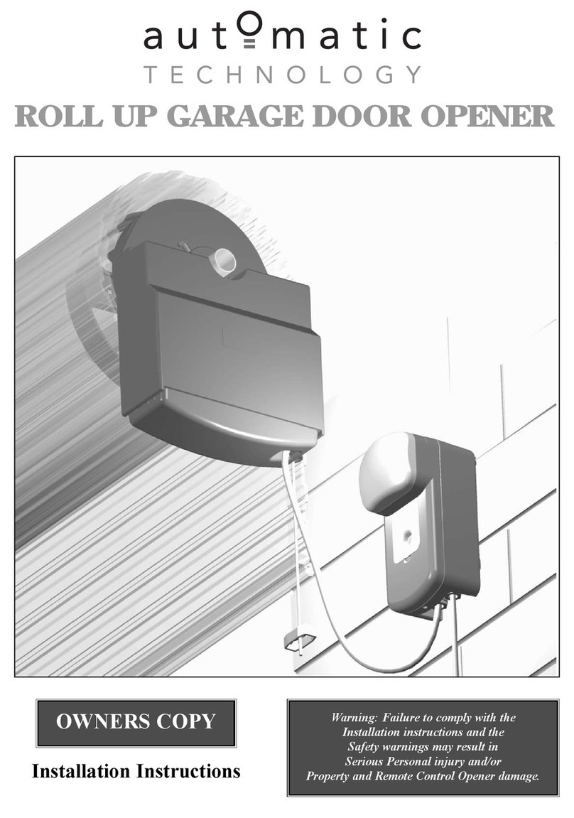
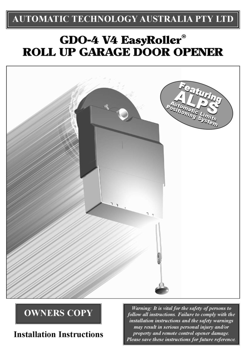
Automatic Technology Australia EasyRoller GDO-4 Quick start guide

Automatic Technology Australia Pty Ltd
EasyRoller
GARAGE DOOR
OPENER
lnstallation
lnstructions and Owners
Manual for GDO,4
Garage Door Opener

Gontents
USER SAFETY INFORMATION
FEATURES
OPERATING CONTROLS
PACKAGE CONTENTS
SEOUENCE OF INSTALLATION
INSTALLATION
FAULTS AND REMEDIES
PARTS LIST
TECHNICAL SPECIFICATIONS
OPTIONS AND ACCESSORIES
WARRANTY AND EXCLUSION OF LIABILITY
PAGE
I
I
2
4
4
5
1t
12
13
t3
14
U

User Safety lnformation
lnstall the wall switch in a
location/position where the
garage door is yisible and
A Garage door must be well out of reach ol children. objects including motor vehicles
/t\ oaranced. Sticking or binding fi only operate the garage within the doorway'
4\ (e6;s must be repaired by a / I \ door opener when the garage A When using auto close mode a
qualified garage door installer Adoor is in.futl view and free /I\ photo electric beam must be fitted
prior to operator installation. from obstructions. / ' \correctly and tested for operation
A Connect the operator to a
fl\ prop"rry grounded general
A purpos e 24oV outlet installed by
r oualified electrical contractor
v
and/or property damage, This, A Keep hands anct any loose
test must be repeated at reoular /il . ..'.
intervals and the n*"*""*-'"'*' /I\ clothinq clear of door and door
Featufies
PLEASE READ
THESE IMPORTANT
SAFETY RULES
Do not attempt to repair door
yourself as hardware is under
extreme tension and
can cause serious personal
injury and/or property damage
Remove or disengage all
garage door locks prior to
installation of operator.
Make sure that the reversing
sensitivity is adjusted correctiy on
installation so that the door
reverses to the open position
when obstructed. Failure to
adjust this setting propedy could
result in serious personal injury
Your EasyRoller Automatic Garage
Door Opener has many features
which you will appreciate. The
Components and Materials used in
'his Automatic Opener are of the
\ratest Technology and highest
Quality. Below are listed some of
the features.
OPERATION
To operate the door simply press
the hand held transmitter or the
wall mounted switch for two
seconds and the door will
automatically open or close. The
door can be stopped during an
opening or closing cycle by
pressing the wall switch or
handheld transmitter. The next
actuation will move the door in the
opposite direction.
SAFETY OBSTRUCTION
REVERSE
While the door is doing a closing
cycle and it should hit an obstacle
or be restricted in some manner, it
will automatically reverse. The
amount of force the door should
encounter before reversing is
adjustable. The door also if
restricted whilst opening will
Do not allow children to sperate
the garage door opener.
Serious personal injury and/or
property damage can result from
failure to follow this warning. A
Do not operate the garage door ll_\
opene r when children/persons
are near the door- Children must
be supervised near garage door
at all times and when door
operator is in use. Serious
personal injury andlor property
damage can result irom failure to
follow this warning.
Disconnect power cord from
mains power before making any
repairs or removing covers.Only
qualified service personnel can
remove coverg from opener.
stop. The Safety Obstruction
Forces should be checked at least
once a month.
AUTOMAT!C
COURTESY LIGHT
The Courtesy Light on the Opener
comes on automatically whenever
the door is activated to do an
opening or closing cycle. The light
will stay on for approximately ihree
minutes then turns off
automatically. The Light can also be
switched on and off without
operating the door. This is done by
pressing the Light button on the
Wall Switch. The Light turns off
after three minutes.
MANUAL OPERATION
The Opener is equipped with a
unique Manual Disengaging
Device. lf the power to the Opener
is disrupted for any reason the door
can be put into Manual Mode by
pulting down on the string handle,
then releasing. This will allow you to
manually open or close the door.
When power is restored, by pulling
down on the string handle and
releasing, the Opener is put back
into Automatic Mode.
Do not disengage the door
opener to manual operation with
children/persons or any other
at regular intervals. Extreme
caution is recommended when
using auto close mode. All safety
rules above must be followed.
Automatic Technology Australia
Pty. Ltd. to the extent that such
may be lawfully excluded hereby
expressly disclaims all conditions
or warranties statutory or othen|ise
which may be implied by law as
conditions or warranties of
purchase of an Automatic
Technology Australia Roll-Up-
Door Opener and Automatic
Technology Australia Pty. Ltd.
hereby further expressly excludes
all or any liability for any injury.
damage, cost, expense or claim
whatsoever suffered by any
person as a result whether
directly or indirectly from failure to
install the ATA Easy Roller Roll-
Up-Door in accordance with these
installation instructions.
SECURITY GODE STORE
The Opener uses state of the art
technology in storing your selected
Transmitter Security Code. Up to
sixty different codes can be stored
in the non volatile memory device.
To store any code simply press and
hold the Code Store button on the
Opener and press the Transmitter
button twice. Each or all codes can
be deleted and changed at any
time. Security is enhanced because
there are no Dip switches on the
Opener which can be visually seen
and copied.
cAs (colouR
ASSTSTED SETTTNGS)
To make the installation of the
Automatic Opener more user
f riendly Automatic Technology
Australia developed the CAS
(Colour Assisted Settings) System.
This unique system allows for all
the Open and Close adjustments
and settings to be colour
coordinated, Red for Close and
Green for Open. The colour
coordination makes it easier and
quicker for the user or installer to
complete the installation.

Featurgs cont...
OPEN AND CLOSE
DRIVE BUTTONS
Another feature developed by
Automatic Technology Australia in
aiding in the installation of the
Opener are the Open and Close
Drive Buttons. These buttons are
used to help set the open and close
limit positions. The quicker
setting time and a more precise
limit position can be achieved
using this system.
AUTO CLOSE MODE
The Opener can be programmed
to automatically close
approximately thirty seconds after
the door has opened. A Photo
Electric Beam must be installed if
this mode is selected.
AUTO RUN TIME
lf the Motor is left running in the
Opener for any reason the Auto
Run Time will turn the motor off
after thirty seconds.
PHOTO ELECTRIC BEAM
The Opener has an input for a
Photo Electric Beam to be
connected for extra safety protection.
15. AUTO CLOSE (J2) lnput is
used for selecting the auto
close mode. lf auto close is
selected the door will
automatically close
approximately 30 seconds after
opening. To select, remove
shunt from P.E. input connector
and place on auto close
connector pins. NOTE: a P.E.
Beam must be used when auto
close is selected.
16. SEGURALIGHT lnput is used
for connecting a Securalight
(optional extra) Monitor. A
Securalight is a monitor unit
which is mounted inside your
home and is connected to the
Opener by wire cable. The
monitor indicates the status of
the door, for example if the
door is moving, is opened or
closed, etc. An audible beeper
sounds whenever the door is
moved by the Opener. The
door can also be controlled
from the monitor unit.
17. O/S/C lnput is for connecting
the Wall Switch.
18. WALL SWITCH is usuatty
mounted inside the garage.
Pressing the Open / Close
button on the wall switch will
open, close or stop the door.
Pressing the Light button will
turn the light in the Opener on
or off. lf the light comes on and
you do not press to turn off, the
light will turn off automatically
after about 3 minutes.
19, ENGAGVDISENGAGE
HANDLE when pulled down
and released will select
manual mode when there is a
power failure. Pulling down and
releasing again will select
automatic mode.
20. STANDBY BATTERY SHUNT
must be removed when using
Battery Back Up Option.
1.
2.
3.
4.
5.
6.
v
Operating Gontrols
O/S/C Button (yellow) is used
during installation to test the
open, close and stop
commands to the Opener.
Pressing this button will open,
close or stop the door.
CODE SET Bufton (blue) is
used for storing or erasing your
selected security code from
your transmitter(s) into the
Openers memory device.
OPEN DRIVE Button (green)
is used during installation to
help set the open limit stop
position. Pressing and holding
this button will move the door
in the open direction.
Movement stops when the
button is released or when the
open limit switch is activated.
NOTE: The open obstruction
detection is inoperable
whenever the Open Drive
button is used to move door.
OPEN LIMIT Led (green)
illuminates whenever the open
limit switch is activated. The led
is very helpful during installation.
CLOSE DRIVE Button (red)is
used during installation to help
set the close limit stop position.
Pressing and holding this
button will move the door in the
close direction. Movement
stops when the button is
released of when the close
timit switch is activated.
NOTE: The close safety
obstruction detection is
inoperable whenever the
Close Drive button is used to
move door.
CLOSE LIMIT Led (red)
illuminates whenever the close
limit switch is activated. The led
is very helpful during installation.
OPEN FORCE ADJUSTMENT
Shaft (green) is for adjusting
the open obstruction force.
Turning the shaft in a clockwise
direction increases the force
that is required to restrict the
door before it stops when
opening. Turning anticlockwise
will decrease the force that is
required to stop the door.
8. CLOSE FORCE
ADJUSTMENT Shaft (red) is
for adjusting the close safety
obstruction force. Turning the
shaft in a clockwise direction
increases the force that is
required to restrict the door
before it reverses when
closing. Turning anticlockwise
will decrease the force that is
required to reverse the door.
NOTE: The open and close
safety obstruction forces need
to be tested at regular intervals
(once a month) and the
necessary adjustments made.
9. OPEN LIMIT CAM (green) is
used to set the open limit stop
position. Check lnstallation
section on how to adjust.
10. OPEN LIMIT ADJUSTMENT
SCREW (green) is used to fine
adjust the open limit stop
position. Check lnstallation
section on how to adjust.
11. CLOSE LIMIT CAM (red) is
used to set the close limit stop
position. Check lnstallation
section on how to adjust.
12. CLOSE LIMIT ADJUSTMENT
SCREW (red) is used to fine
adjust the close limit stop
position. Check lnstallation
section on how to adjust.
13. P.E. lnput is for connection of
Photo Electric Beams (optional
extra) for extra safety
obstruction protection. The P.E.
shunl must be removed when
a PE. is connected.
14. P.E. SHUNT must not be
removed othenarise the Opener
wilt not function correctly.
Remove only when a P.E. is to
be connected
7.

Operating Gontrols
IPIRATlNG CINTRNLS
?ffi
tt
m"ll
ll
)g
1. O/S/C button
2. Code set button
3. Open drive button
4. Open limit LED
5. Close drive button
6. Close limit LED
7. Open force adjustment shaft (green)
8. Close force adjustment shaft (red)
9. Open limit cam (green)
10. Open limit adjustment screw (green)
11. Close limit cam (red)
12. Close limit adjustment screw (red)
13. PE. input
14. PE. shunt
15. Auto close input
16. Securalight inout
17. O/S/C input
18. Wall switch
19. Engage/disengage handle
20. Battery shunt

Package Gontents
ITEM
DRIVE UNIT
HAND TRANSMITTER
WALL SWTTCH (WrrH WrRE)
BATTERY (9VOLTS)
WETGHT BARS (NOT TNCLUDED rN SOME COUNTRTES)
SELF TAPPING SCFIEWS (M4 X 25mm)
INSTALLATION MANUAL
qUANTITY
1
1
1
1
2
4
1
Sequence of lnstallation
f,
HAND
TRANSMI T TER
VALL
SVITCH
DRIVE UNIT STRING
HANDLE
BATTERY
VEIGHT BARS

lnstallation
SIDE ROOM REQUIREMENTS
Figure 1 shows the minimum side room that is required.
The distance between the edge of the door curtain and the inside of the
bracket is B5mm and the distance between the edge of the door and the
outside of bracket is 135mm.
Figure 2 shows the recommended side room. The distance between the
edge of the door curtain and the inside of the bracket should be 11Omm
minimum and the distance between the edge of the door and the outside
of bracket should be 160mm minimum.
I. CHECK OPERATION OF DOOR
BEFORE BEGINNINGTHE INSTALLATION OFTHE EASY ROLLER
AUTOMATIC OPENER CHECKTHE OPERATION OFTHE DOOR.
The door must be well balanced and be in a reasonable operating
condition. The door should not stick or bind in the guide tracks. The ideal
operational effort in raisrng or lorvering the door should not exceed a force
'rf 15 kgs (33 lbs.). The maximum effort should not exceed a force of 25
U(gs (55lbs.).
2. FIXING OF DOOR WEIGHT BARS
Move the door manually to mid open position. Place the weight bars
equally apart on the bottom rail of the door and secure them with the
fasteners provided (see Fig. 3). Check the operation of the door again. lf
the door feels heavy it may require exira tension to be added to the door
springs. Refer to the Door lnstallation Manual from the manufacturer on
how to tension the door.
3. IEFT OR RIGHT HAND INSTALLATION
The Easy Roller Automatic Opener can be installed on the left or right
hand side of the door (when looking out from the inside of the garage). lf
your opener is to be installed on the RIGHT HAND side of the door then
go on to Step 4. lf the left hand side is your selected side for installation
the next siep is to move the motor wire connector (labelled J12 on the
control board). The connector has to be removed and reconnected to the
i-EFT side of J12 which is marked A:B (see Fig. 4).
ttlT you have made an error in selection and wish to install to the RIGHT
HAND side of the door then reconnect the connector to the RIGHT side oI
J12 marked B:C (see Fig. 5).
M]NIMUM SIDf RtrtrM
RECIMMENDED SIDE RINM
160 mm
\/EIGHTS
MOTOR VIRE CONNECIED
rOR LEFT HAND SIDE
INSTALLATION (AB)
ABC
FIG.4
MOTOR VIRE CBNNECTED
FOR RIGHT HAND SIDE
INSTALLATION (BC)

lnstallation cont...
4. FIXING DRIVE ASSEMBLY TO DOOR
The Easy Roller Drive Assembly can be fixed to the Roll Up Garage Door
in a variety of ways. Below we will describe one method of fixing. Make
sure there is enough room (135mm from end of door shaft to the wall) to
slide drive assembly onto shaft.
PLEASE NOTE: THE INSTRUCTIONS FOR FIXING OF THE DRIVE
ASSEMBLY TO THE DOOR IS FOR RIGHT HAND INSTALLATION.
FITTING DRIVE ASSEMBLY TO DOOR
(see Fig.6,Fig.7, and Fig.8 ).
(a) Check that the door shaft U bolt is securely tightened on the left hand
side of the door.
(b) Baise the door and tie a rope around the centre to secure the roll.
(c) Support the right hand end of the door with a suitable prop, e.g. step
ladder and soft padding to protect door surface.
STOP. WARNING: DO NOT ALLOW CHILDREN/PEFISONS
AHOUND THE DOOR WHEN PROPPED. SERIOUS PERSONAL INJURY
AND / OR PROPERTY DAMAGE CAN RESULT FFIOM FAILURE TO
FOLLOW THIS WARNING.
(d) Check that step 3.1a was completed. Carefully loosen and remove the
right hand door shaft U bolt.
(e) Make sure that the door supporting prop is secure. While the door is
supported remove the right hand door mounting bracket from wall.
(f) Remove the Drive Assembly from packaging. Try and rotate the drive
gear by pushing on the fork. lf the gear does not rotate the manual
mode has to be selected. To select pull on the string handle
downwards, then release slowly. The drive gear should now rolate.
(g) Slide Drive Assembly over the door axle making sure that the fork
extends into and over one of the spokes of the door drum wheel.
(h) Refit the door mounting bracket to the wall. ln some cases the bracket
may have to be repositioned. Retighten the door shafi U bolt.
Remove door supporting prop and untie rope from curtain.
Straighten the Drive Assembly and position as per figure B. Tighten
the two locking bolts firmly to secure Drive Assembly.
Check the manual operation of the door by raising and lowering the
door. The door should run smoothly and not catch on any part of the
Drive Assembly.
5. SETTING LIMIT SWITCHES
The Limit Cams, Limii Fine Adjustment Screws and Door lnch Buttons are
colour coded to make the setting of the limits as user friendly as possible.
The GREEN colours for OPEN LIMIT SETTING. The RED colours for
CLOSE LIMIT SETTING.
5.1 SETTING LIMITS FOR RIGHT HAND INSTALLATION
(a) With the Drive Assembly in manual mode (disengage, see Fig. 12),
move the door up by hand to the desired open position.
(b) Remove the Light Diffuser (see Fig. 9). Rotate by hand in an
anticlockwise direction the green limit cam (see Fig. 10) until the cam
clicks the open limit switch.
(c) Move the door down by hand to the desired closed position.
(d) Rotate by hand in a clockwise direction the red limit cam (see fig. 11)
until ihe cam clicks the close limit switch.
(e) Connect power lead from
the Drive Assembly into a general purpose power outlet installed by a
licensed qualified electrical contractor. Turn the Power On.
(0 Fle-engage the drive gear by pulling down on the string handle and
then releasing slowly (see Fig. 12)
6
(i)
(i)
(o) CHECK IF
,U' BOLT IS
TI6HTENED
(d) REMOVE RIGH'I
-U' BOLT
\
FIG. 7
TO REMT]VE
LIGHT DIFUSER
FIG. 9
FI6. 8

OPEN LIMIT ADJUSTMENT
(g) Press in and hold the Green Open lnch Button. The door should start
opening. Release the inch button when the door reaches the desired
open position. lf the Green LED (see Fig. 10) is illuminated and the
desired limit position has been reached then the limit adjustment is
complete. lf the Green LED is illuminated but the door has not
reached, or has gone past the desired position, you have to adjust the
Green Fine Adjustment Screw (see Fig. 10). Adjust the screw
anticlockwise to open the door more. To open the door less adjust the
screw clockwise. Each complete revolution of the adjustment screw is
equal to approximately .1 Omm of door travel.
NOTE: lf the door has not reached the desired limit position by more
than 30mm, it is recommended that the green limits cam be adjusted
again before the green fine adjustment screw is adjusted.
CLOSE LIMIT ADJUSTMENT
(h) Press in and hold the Red Close lnch Button. The door should start
closing. Release the inch bution when the door reaches the desired
y closed position, lf the Red LED (see Fig. I1) is illuminated and the
desired position has been reached then the limit adjustment is
complete. lf the Red LED is illuminated but the door has not reached,
or has gone past the desired position, you have to adjust the Red
Fine Adjustment Screw (see Fig. 11). Adjust the screw anticlockwise
to close the door less. To open the door more adjust the screw
clockwise. Each complete revolution of the adjustment screw is equal
to approximately 1Omm of door travel.
NOTE: if the door has not reached the desired limit position
by more than 30mm, then it is recommended that the red
limits cam be adjusted aQain before the red fine adjustment
screw is adjusted.
5.2 SETTING LIMITS FOR LEFT HAND INSTALLATION
(a) With the Drive Assembly in manual mode, move the door up by hand
to the desired open position.
(b) Remove the Light Diffuser (see Fig. 9). Rotate by hand in a clockwlse
direction the Green Limit Cam (see Fig. 13) until the cam clicks the
open limit switch.
b) Move the door down by hand to the desired closed position.
St(d) Rotate by hand in an anticlockwise direction the red limit cam (see
Fig.14) until the cam clicks the close limit switch.
(e) Connect Power Lead from the Drive Assembly into a general purpose
power outlet installed by a licensed qualified electrical contractor.
Make sure that the Power Lead is safely fastened away from any
moving parts. Turn the Power On.
(f) Re-engage the drive gear to door by pulling down on the string handle
and then releasing slowly (see Fig. 12).
OPEN LIMIT ADJUSTMENT
(S) Press in and hold the Green Open lnch Button. The door should
start opening. Release the inch button when the door reaches the
desired open limit stop position. lf the Green LED (see Fig. 13) is
illuminated and the desired limit stop position has been reached then
the limit adjustment is complete. lf the Green LED is illuminated but
the door has not reached the desired position, you have to adjust the
Green Fine Adjustment Screw (see Fig. 13). To open the door more,
adjust the screw anticlockwise. To open the door less adjust the screw
clockwise. Each complete revolution of the adjustment screw is equal
to approximately 'lomm of door travel.
NOTE: lf the door has not reached the desired limit position by more
than 30mm, it is recommended that the green limits cam be adjusted
again before the green fine adjustment screw is adjusted.
FIG, 11
OR
RE-EN6A6E
FIG. 12
^NIICLEXVISE rO @EN @E
cL&xvtsE ro @N LEss IOIAIE 6FEEN 'N
@Hp
F1G, 13

lnstallation conr...
CLOSE LIMIT ADJUSTMENT
(h) Press in and hold the Red Close lnch Button.The door should start
closing. Release the inch button when the door reaches the desired
closed limit stop position. lf the Red LED (see Fig. 14) is illuminated
and the desired limit position has been reached then the limit
adjustment is complete. If the Red LED is illuminated but the door has
not reached, or has gone past the desired position, you have to adjust
the Red Fine Adjustment Screw (see Fig. 14). Adjust the screw
clockwise to close the door less. To close the door more adiust the
screw anticlockwise. Each complete revolution of the adjustment screw
is equal to approximately 1Omm of door travel.
NOTE: lf the door has not reached the desired limit position
by more than 30mm, then it is recommended that the red
limits cam be adjusted again before the red fine adjustment
screw is adjusted.
6. FIXING OF DOOR CURTAIN TO DRUM WHEEL
The Door Curtain has to be secured to the drum wheel with
suitable fasteners.
(a) With the door in the fully closed position mark the curtain (as per Fig.
15) on both ends of the door.
(b) Open door slightly to have access to the marked positions. Secure the
curtain to drum wheel using self drilling screws (two on each end). The
screws should be at least 90 degrees apart as per Fig. 15.
7. SETTING OF CLOSE SAFETY OBSTRUCTION AND
OPEN FORGE
lmportant: The setting for the open and close obstruction forces are the
most important adjustments that are made in the whole installation
procedure. Make sure that the force (load ) is adjusted correctly as per the
installation instructions. Failure to adjust these settings correctly could
result in serious personal and /or property damage. The end user musl be
informed that they must test at regular intervals (once a month is
recommended) these settings and the necessary adiustments
made if required.
Note: The Open and Close Obstruction Force ad.lustments procedure are
the same for Left or Right Hand installation.
7.1 CLOSE SAFETY OBSTRUCTION FORCE ADJUSTMENT
(a) Fully open the door by pressing in and holding the green
inch button. The door will stop automatically when the open limit
position is reached.
(b) Turn the Red Close Force Shaft fully clockwise. Press the Yellow
O/S/C (open, stop,close) button (see Fig. 16) momentarily, the door
should stgrt closing. As the door is closing turn the Red Shaft slowly
anticlockwise until the door stops momentarily then reverses to the
open position.
(c) Turn the Red Shaft 10' clockwise, Press the Yellow button to close the
door. lf the door reverses by itself, readjust the Red Shaft a further 5"
clockwise. Keep adjusting in this manner until the door can complete
the full closing cycle.
FIG. i4
DRUI,,I VHETL
+-+
(o) (b)(c)
l/
FIG. 16
u

7.2 OPEN OBSTRUCTION FORCE ADJUSTMENT
(a) Fully close the door by pressing in and holding the green
inch button. The door will stop automatically when the closed limit
position is reached.
(b) Turn the Green Close Force Shaft fully clockwise. Press the Yellow
O/S/C (open, stop, close) button (see Fig.17) momentarily, the door
should start opening. As the door is opening turn the Green Shaft
slowly anticlockwise until the door stops.
(c) Turn the Green Shaft 10" clockwise. Press theYellow button to open the
door. lf the door stops by itself, readjust theGreen Shaft a further 5"
clockwise. Keep adlusting in this manner until the door can complete
the full opening cycle.
7.3 CLOSE SAFETY OBSTRUCTION TEST
The door now has to be tested for response to an obstruction while it is
opening and closing. With the door in the opened position, place a solid
object approximately I metre in height underthe door (see Fig. 18). Press
"the Yellow button to close the door. When the door reaches and pushes on
\-.ie object it should pause then reverse up to the open position. Repeat
the above and observe the action of the door as it pushes against the
solid object. Undue load should not be applied to the door. The load
imposed by the door should be around I to 10k9. The load can be tesied
by placing a bathroom scale on the floor under the door, start a close
cycle and read the scale as the door pushes down against the scale. lf the
reading is too high. readjust the Red Close Force Shaft. Turning shaft
clockwise increases the load applied to the door. Turning shaft
anticlockwise decreases the load applied to the door.
IMPORTANT: IF THE DOOR IS UNABLE TO REVERSE WHEN
OBSTRUCTED DISCONTINUE USE. SELECT MANUAL MODE AND
CONTACT AUTOMATIC TECHNOLOGY AUSTRALIA PTY LTD.
8. SETTING OF TRANSMITTER AND RECEIVER
SECURITY CODE
8.1 SETTING THE TRANSMITTER
(a) Remove the sliding cover from the back of the Transmitter (see
Fig.19). The coding switches are located under the slide of back
-. cover (see Fig. 19).
\o) Using a pen or similar instrument, move the code switches so as to
form a random looking pattern. For example switches i,2,5,7,8,10
and 11 in the off position and 3,4,6,9,12 in the on position (see Fig.
19). The selected pattern forms the Transmitter Code.
(c) Connect the 9V Battery to Transmitter. Slide the back cover
back into position.
8.2 STORING THE TRANSM!fiER CODE INTO THE
CONTROLLER'S RECEIVER
The memory in the controller's receiver can store up to 60 different
transmitter codes.
(a) Press and hold the Blue Code Set Button on the Control
Panel (see Fig. 20).
(b) Press the Transmitter Button for approximately two seconds.
Pause for 2 seconds. Press the Transmitters Button again for
approximately two seconds.
(c) Release the Code Set Button.
(d) Press the Transmitter Button to see if it operates the door.
(e) Uncoil the Antenna Wire and stretch it out against the Garage Wall in
a horizontal or vertical direction (try and keep the antenna wire away
from metal objects). Secure wire with suitable fasteners. Do not cut
the antenna wire or coil up.
IMPORTANT: Only operate the Garage Door Opener when the
Garage Door is in full view and free from obstructions.
(o) (b)(c)
AUTO
CLOSE
@
@
FIG. 17
FIG. 18
FIG. 19
1,.:,r$,,r

lnstallation cont...
8.3 DELETING THETRANSMITTERS CODE FROMTHE
CONTHOLLERS RECEIVER
lf you only want to delete one transmitter code stored then use step 8.3a
to d. Use step B.3e to h if you want to delete all the stored transmitter
codes.
(a) Select the transmitte(s) you want to delete from memory.
(b) Press and hold the Blue Code Set Button on the Control
Panel (see Fig. 20).
(c) Press the Transmitter Button for approximately two seconds.
Pause for two seconds. Press the transmitters Button again for
approximately two seconds.
(d) Release the Code Set Button. The code should now be deleted.
Confirm this by pressing the transmitter button to see if it can
operate the door.
Turn the Power Off to the Drive Unit.
Press and hold the Blue Code Set Button on the Control panel.
Turn the Power back On again.
Release the Code Set Button after three seconds. All the Stored
codes should be now deleted. Confirm this by trying to operate the
door by pressing one of the deleted transmitters.
(e)
(0
(s)
(h)
9. FITTING WALL SWITCH
(a) Remove the front cover from the Wall Switch. Take note of the
orientation of the Switch, the Open/Close Button must be to the top
when mounting to the wall.
(b) Locate the Wall Switch in a convenient position. Make sure thai you
mount the Switch higher than a child can reach and in a position
where the door is clearly visible.
(c) Connect the three wires, and secure to wall with the two screws
provided (see Fig. 21).
(d) Connect plug from the-.wai-switch wire to the connector marked
O/S/C (J6) on the control board.
NOTE: The descriptions (e), (f) and Fig.22 are for Right Hand lnstallation.
For Left Hand lnstallation break the tab and use the cable restrainers on
the opposite side.
fl)
Secure wall switch wire to the control board with the cable
restrainer provided.
Break away the plastic tab with a pair of pliers to create an exit point
for the wire from the Drive Unit (see Fig. 22)
Check the exit point of the wire from the switch base and remove
material from the front cover of switch,so that the cover does not cut
through the wire.
Reposition the two buttons in the front cover and refit over the switch
base by pushing on cover.
Fasten wire to wall with suitable fasteners. Make sure not to break
through tle wire insulation when fastening. Breaking the insulation
will create a short in the wire.
Refit the light diffuser.
Test the operation of the switch by pressing the Open/Close Button to
move the door.
While the door is siationary press the Light Button to turn the light on
the opener On and Off.
(e)
(f)
(s)
(h)
(i)
(i)
(k)
@*p
.I
El
'i
FIG. 21
10

Faults and Remedies
SYMPTOMS POS,SIBLE CAUSE REMEDY
tr Door will not operate tr Main power not turned on
tr Door is obstructed Turn on
Remove obstruction
tr
tr
tr Door is locked or
motor jammed tr Unlock door
tr Door will not reverse
tr Door moves downwards and
reverses itself upward
. . 1 Door ooerates from
t drive unit but not from
hand transmitter
tr Door reversing sensitivity not
adjusted properly
Door reversing sensitivity
not adjusted properly
lndicator on transmitter
not lighting
Code not stored in
controlling receiver
Drive unit aerial wire
not extended
Battery flat
Radio interference
Fle-adjust reversing sensitivity
(Ref installation instructions
Step 7.1)
Re-adjust reversing sensitivity
(Ref installation instructions
Step 7.1)
Battery flat or battery
leads broken
Refer to installation
instructions-Step 8.2
Extend aerial wire
Replace battery
Return operator to place of
purchase for frequency
upgrade (charges apply)
tr
tr
tr
tr tr
tr
1tr
o
tr
tr
tr
tr
D Door open/closes by itself
v,
tr lncorrect coding D Change the numerical
coding on transmitter
and receiver (please
ensure at least 4 switches are
in the on position)
tr Door does not close fully tr Limit microswitch
incorrectly adjusted tr Re-adjust limit switch
(refer to installation
instructions-Step 5)
tr Door does not open fully tr Limit microswitch
incorrectly adjusted tr Re-adjust limit switch
(refer to installation
instruction-Step 5)
tr Lights not functioning tr Globe blown O Replace globe
tr Replace with 24VDC '15 Watts
Festoon Globe
tr Globes keep blowing I lncorrect globe

Parts List
Item No Description
4
5
6
7
8
o
10
11
12
13
14
15
16
2
3Limits Base
Adjustment s':rer, green/red
Switch holder green\red
E circlip D1500 0040
lvliniature microswitch
Disengagement spring
l\,4otor base
Cam
Disengagement lever
Disengagement shaft
Cam spring
Limits cam guide
Limit cam green-limit cam red
Plastic base
clamp
Drive ass'y 7
Worm shaft
Gear 1
Limits shaft
Board support
Helical gear 2610
lnternal gear
I\,4ain cover
Light diifuser
Board cover
Control board assy CB-7 V1 .00
Worm support
Limits bush
Controls label
Logo label right
Worm washer
' Disengagement cap
Disengagement washer
Transf orme r TF6 1 7 06 I 1 2-3
Terminal block 500/02DS 2 Pos
Cord grip grommet SB-6R-3
String 600mm
Hex. Head screw m8x25
Hex {lange hd. Screw m6xl6
Pan. Flange hd. Screw m4x12
Taplite screw "P" m4x10
Taptite screw "P" m3x16
Cap head screw m6
Hex flange nut m6
Retaining ring stw 45
E circlip D.l500 0080
Hex nut m4
String handle
Clamp washer
Special washer
Flat washer LD.5
Hex nut Wint tooth washer m5
ldentity label
Warning label
String guide
,,..€d{'
p.,
43
,1
111
111
4
2
1
1
-I
'1
1
1
1
1t1
2
12
Req'd Order Code
*l
fu.,
lipt'
#:44
i aa
s,,
01 626
01 630/01 628
01 634i01 632
01 083
00928
01 236
00443
00487
01 640
01614
1 239A
00492
00491 /00490
0.1620
01 600
00039
01610
00446
01612
01622
00409
01 602
01 625
0051 2
01624
00099
01 636
00434
01 3s8
01 3s3
00489
00441
01117
0552D
05424
00560
01 544
01011
01017
01 038
01 057
01 055
01 001
0'101 5
01 065
0108'1
01 089
01644
01 118
01 062
01105
1 088A
01 359
01 371
01642
01176
01428
0141s
01 339
01 338
01 031
01049 14G
/"
65
73
3
'I
1
,l
1
2
4
11
12
1
3
4
1
17
18
19
20
21
22
24
26
28
29
30
31
34
JO
37
38
39
40
41
42
43
44
45
4b
48
4S
50
51
53
54
55
56
57
58
59
60
62
64
65
74
Cable clamp acc-2.5 (5/16")
Harness microswitch
Power cord 1.5M + ring
Logo label left
Cord label
Pan. Head screw m4x12
Taptite screw "S" m3.5x6
75
83
84
I
@4s
I
!
564
a
57
l8
t9
50
s"
54
12

Technical Specifications
INPUT VOLTAGE:
TRANSFORMER SPEC.:
MOTOR SPEC.:
CONTROL BOABD SPEC.:
ry'IANSMITTER SPEC.:
OPENER LIFTING CAPACITY:
23OVl 24OV AC 50 Hz
(110V AC 60 Hz or 127V AC 60 Hz available on request)
Single Phase
Current Required
Primary Voltage
Secondary Voltage
Motor Type
Voltage
Torque
Relay Contact Rating
Relay Coil Voltage
Control Board Voltage
Light Globe Voltage
Recerver Specif ication
24VDCl5VDC
24V DC / 15 Watts
Recerver Type
HF Frequency
lntermediate Frequency
Code Storage Capacity
1 Amp
230 I 240V AC
24V AC / 100 VA
Permanent Magnet D.C. Motor
24V DC
135 kg cm at 4 Amps
10Amp/30VDC
24V DC
27.145 MHz
50 mA (approx)
9 Volts
PCM 12 Bit Binary (4096 Code Combinations)
Channel
MECHANICAL
KEY RELEASE
Narrow Band FM
(Superhetrodyne)
27.145 Mhz
455 Khz
60 Different Codes
SECURALIGHT
MONITOR
Carrier Frequency
Current Consumption
Battery Voltage
Coding Format
30 kg
Accessories
TX SERIES HANDHELD
TRANSMITTERS
One,Two & Four Channel
KPX.4/KP.4 WIRELESS
DIGITAL KEYPADS
ELECTRONIC
KEY RELEASE
CRXA.I/2 SERIES
ffi?

AUTOMATIC TECHNOLOGY AUSTRALIA PTY LTD
17-19 Advantage Rd, Highett, Victoria, Australia, 3190.
Ph: (03) 95322788 Fax: (03) 95322799
E*mail: ata @ ata. net.au
Web : http://www. ata. net. au
Table of contents
Other Automatic Technology Australia Garage Door Opener manuals
Automatic Technology Australia
Automatic Technology Australia GDO-5-AS User manual
Automatic Technology Australia
Automatic Technology Australia GDO-4 V4 EasyRoller User manual

Automatic Technology Australia
Automatic Technology Australia GDO-4 V4 EasyRoller User manual
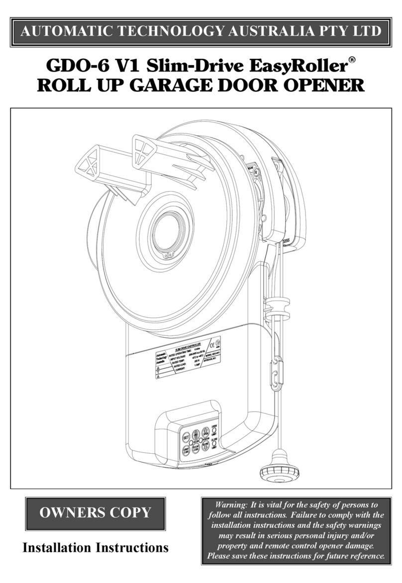
Automatic Technology Australia
Automatic Technology Australia GDO-6 V1 Slim-Drive EasyRoller User manual
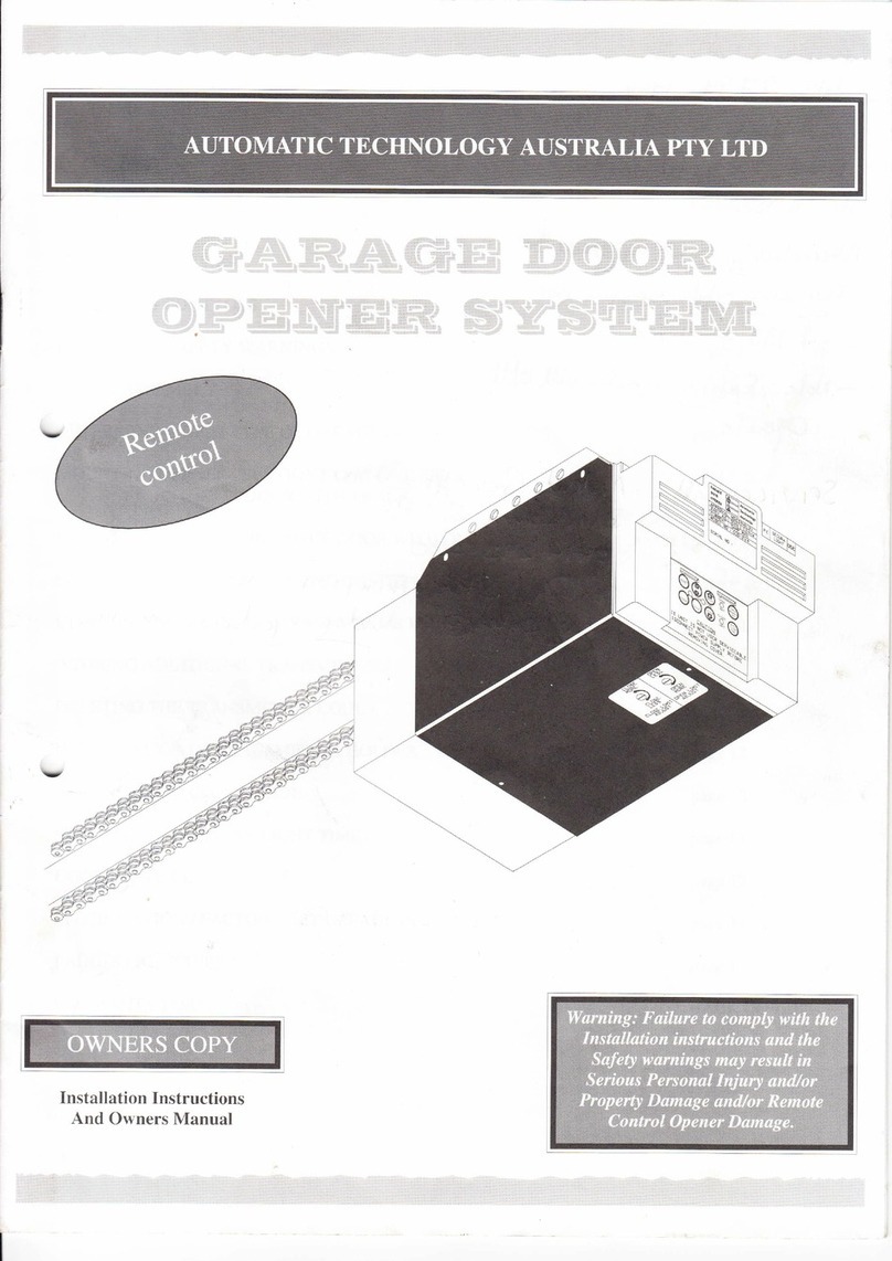
Automatic Technology Australia
Automatic Technology Australia Securalift GDO 2v4 Quick start guide
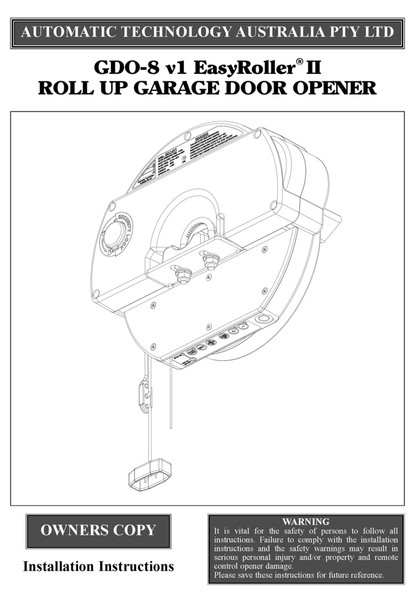
Automatic Technology Australia
Automatic Technology Australia GDO-8 v1 EasyRoller II User manual
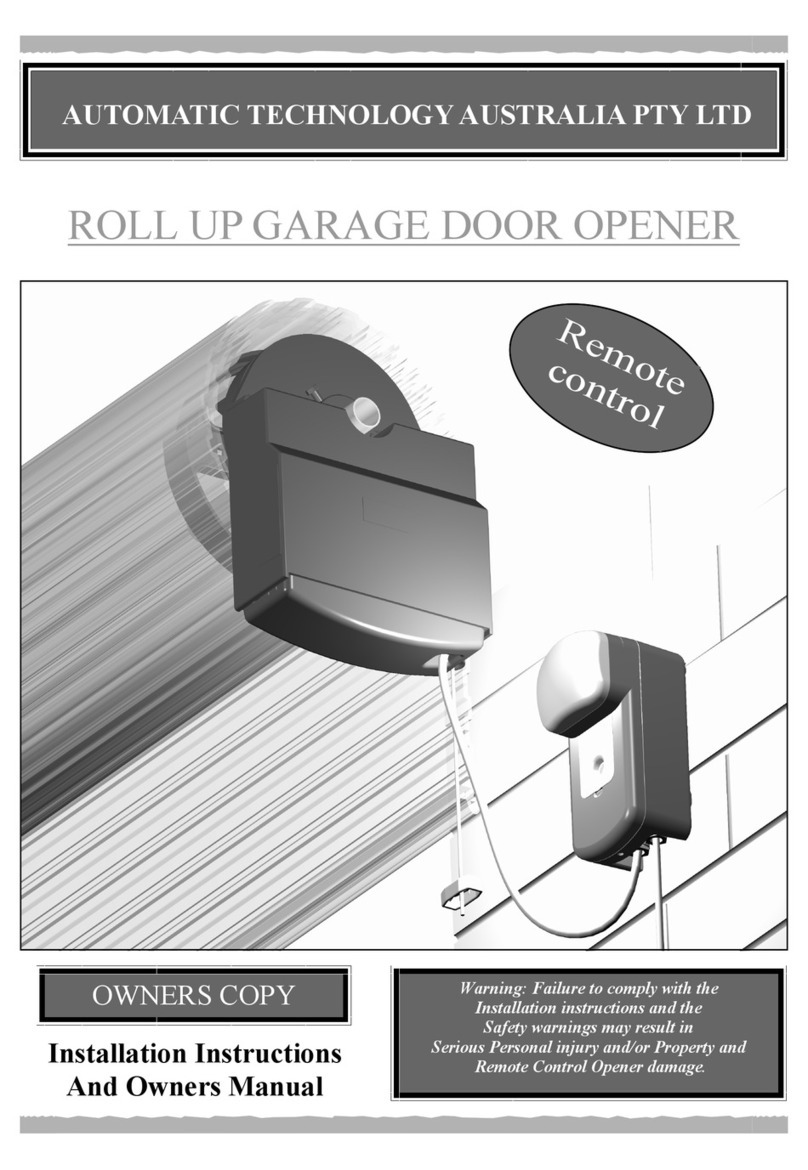
Automatic Technology Australia
Automatic Technology Australia ROLL UP GARAGE DOOR OPENER Quick start guide

