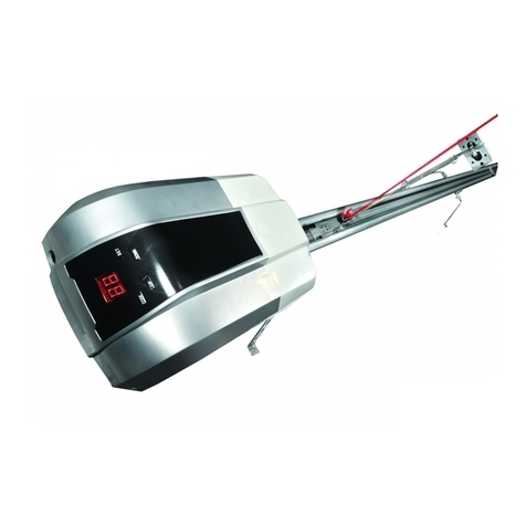
AN-Motors ASG600/3KIT User manual

РУКОВОДСТВО
ПО МОНТАЖУ И ЭКСПЛУАТАЦИИ
Комплекты серии ASG/KIT
для автоматизации гаражных ворот
ASG600/3KIT
ASG1000/3KIT
ASG1000/4KIT
Installation and operation manual
Sets series ASG/KIT for automation of garage doors

2
CONTENTS
1.
2.
2.1.
2.2.
3.
3.1.
3.2.
3.3.
4.
4.1.
4.2.
4.3.
4.4.
4.5.
5.
5.1.
5.2.
5.3.
5.4.
5.5.
6.
6.1.
6.2.
6.3.
7.
7.1.
7.2.
8.
9.
10.
General information and safety measures………… ………………….....
PRODUCT DESCRIPTION…………………………………………………………….
Scope of supply ………………………………………………………………..……
Technical characteristics …………………………………………………………..
Installation preparation …………………………………………………………
Preliminary inspection ……………………………………………………….
Tools and materials for installation…….. ………………………………….
Preliminary works ……………………………………………………………………
Installation …………………………………………………………………………………..
Assembling of the drive rail…. …………………………………………………
Installation of the drive on the rail ………………………………………….
Rail fixing to the wall above the doors ………………………………….
Rail fixing to the ceiling ……………………………………………………..
Connection of carriage and door curtain ………………………………
ELECTRIC SUPPLY SYSTEM …………………………………………….
Photo cells installation …………………………………………………..
Control buttons installation …………………………………………….
Other devices installation ………………………………………………..
Accumulator installation ……………………………………………………..
Drive connection to the electric network ………………………….
ADJUSTMENT ……………………………………………………………………………
Adjustment of final positions ………………………………………………
Adjustment of working modes………………………………………………….
Programming of control boards ……………………………………………………
TESTING AND COMMISSIONING …………………………………….
Testing ……………………………………………………………………………………..
Commissioning ………………………………………………………………….
OPERATION ………………………………………………………………………….
DEFECTS AND RECOMMENDATIONS ON THEIR ELIMINATION
STORAGE, TRANSPORTING AND UTILIZATION …………………….
3
4
4
5
6
6
6
7
7
7
9
9
9
10
10
11
11
11
11
12
12
12
13
14
15
15
17
17
17
18

3
1. GENERAL INFORMATION AND SAFETY MEASURES
!
This manual contains important information about safety measures. Before the mount-
ing it is necessary to make a careful study of the mentioned information. Keep this
manual for further application!
!
Installation, connection, final testing of the equipment, commissioning and technical
support must be performed by qualified and trained specialists.
!
Observe safety measures regulated with current normative documents and this manual.
!
Provide standards requirements concerning the construction, installation and operation
of the automated doors (EN 12604, EN 12605, EN 12453, EN 12445, EN 12978), as
well as other possible local regulations and norms.
!
Mounting, programming, adjustment and operation of the drive with violation of the
requirements stated in this manual is not accepted as it may lead to damage, injuries
or impairment.
!
Changing of the elements of the drive or its misuse is not acceptable. Manufacturer and
supplier are not responsible for any damage caused with unauthorized changes of the
product or its misuse.
!
While installation and operation make sure that there are no lien objects, water or oth-
er liquid inside the drive and its other open parts, otherwise switch off the drive and
address to the service center. Operation of the equipment in such conditions is not
safe.
!
Package must be utilized according to the current legislation.
!
If there is a defect which cannot be eliminated with the help of this manual, address to
the service center.
!
In case of conducting any works (installation, repair, maintenance, cleaning, etc.) and
connections inside the drive cut off the power supply. If the switch device is out of the
visibility zone fasten the plate “Don’t switch. Men work” and take measures preventing
the possible supply of energy.
!
In case of power cable damage its replacement must be performed by the specialist
sent by manufacturer or service center.
!
The company holds the right to make any changes in this manual and drive construc-
tion without preliminary notification retaining all mentioned functions.
!
The contents of this manual cannot be used as basis for issuing any claims.

4
2. PRODUCT DESCRIPTION
The set for garage doors automation (further - Set) includes the electric drive (further - Drive)
with the drive rail and serves for automation of the balance system of garage doors.
Set ASG600/3KIT and set ASG1000/3KIT contain the rail ASGR3. Set ASG1000/4KIT contains the
rail ASGR4.
The drive has an electric motor with a self-blocking reduction gear, electric control unit with the
inbuilt radio receiver and lighting (illuminating lamp). The drive can be used with different devices
(accessories) providing additional functions and ensuring safety.
Drive feeding is provided through the chain with ~230В/50Hz. In case of temporal cut-off of volt-
age in the feeding chain the carriage of the drive rail can be unblocked which provides the possi-
bility to move the door curtain manually. The drive can also be fed from the accumulator which
serves as a standby electric supply unit.
2.1. Scope of supply
Table 1 contains the list of elements supplied.
Table 1. Scope of supply
№
Item
Quantity, pcs.
1
Drive
1
2
Installation and operation manual
1
3
Radio control panel
2
4
Drive rail (semi-assembled, in a set with a rope for manual un-
blocking and two stripes for fastening)
1
5
Carriage top part
1
6
Cranked rod
1
7
Forward thrust
1
8
Bracket of fastening the rail to the wall
1
9
U-shaped bracket for fastening the drive to the rail
2
10
U- shaped bracket for fastening the rail to the wall
1
11
Door bracket
1
12
Bracket of fastening the rail to the ceiling
1
13
Bolt М6х14
2
14
Bolt М8х16
6
15
Screw М6х20
4
16
Self-tapping screw М6,3х16
4
17
Nut М6
6
18
Nut М8
6
19
Axis Ø8х25
2
20
Cottar
2
21
Safety label
1
22
Unblocking label
1
!
Screws (dowels) needed for fastening the elements to the wall and ceiling are not in-
cluded in the scope of supply because their type depends on the material and thickness
of the wall.
!
After receiving the product make sure that the set is complete and the elements are
not damaged. In case of damage address the supplier.

5
2.2. Technical characteristics
The mentioned characteristics are stated for the environment with 20 ºС (±5 ºС).
Table 2. Technical characteristics of the drive
Parameter
Value
ASG600/3KIT
ASG1000/3KIT
ASG1000/4KIT
Supply voltage, В
230 (±10%)
Supply frequency, Hz
50
Maximal driving force, Н
600
1000
Force exerted rating, Н
300
400
Speed at force exerted rating, m/c
0,08
0,06
Speed of idle movement (less than), m/c
0,14
0,15
Power consumption, watt
200
300
Power consumption in the waiting mode (less
than), watt
4
Maximal continuous working time, min
4
Maximal number of working cycles with force
exerted rating, cycles/h
8
10
6
Lighting lamp (illumination)
24В/10Вт, base ВА15
Rail length, m
3,2
4,2
Maximal doors height, m
2,4
3,4
Maximal doors area, m2
8,4
12
16
Protection class
I
Protective class of cover
IP20
Range of working temperatures, ºС
-20…+50
Drive dimensions (less than), mm
345х215х120
Drive weight (less than), kg
4,1
4,6
Table 3. Technical characteristics of the radio control unit
Parameter
Value
Code
dynamic
Operating frequency, MHz
433,92
Emissive power (less than), mWatt
2
Transfer cycle (less than), %
10
Radius of action (more than), m
50
Power source for the control unit
battery 12В/type 27А
Number of programmed control units, pcs.
20
Protection class of control unit cover
IP40
Control unit dimensions (less than), mm
55х38х12
Control unit weight (less than), g
33

6
3. INSTALLATION PREPARATION
3.1. Preliminary inspection
Before the installation of the set it is necessary to:
Check all the elements and materials on the possibility of their application and correspondence
to the current regulations.
Make sure that door construction is suitable for automation. The set cannot be applied in
doors with a wicket or pedestrian zone.
Make sure that door dimensions are in the acceptable limits (see part «Technical characteris-
tics»).
Check that the effort required for the movement of door curtain is less than the maximum
driving force (see part «Technical characteristics»).
Check that the effort required for the movement of door curtain makes a half from the force
exerted rating (see part «Technical characteristics»). The reserve of effort is required because
unfavorable weather conditions (such as wind, snow and others) as well as elements natural
wear can lead to application of increasing effort as a result of increase of friction in the sys-
tem.
Check the balance system of the doors that is they must stay immovable in any position.
Evaluate possible risk (stroke, squeezing, jamming, dragging and other damages). Define the
accessories required for elimination of the risks and observing the safety standards.
Make sure that places of accessories installation (photo cells, control buttons and others) are
protected from strokes and the surfaces are strong enough.
Make sure that there are no lien objects, water or other liquid inside the drive and its other
open parts.
Make sure that the drive and its components are positioned away from the source of heat and
open fire. Violation of this requirement can lead to the product damage, cause its malfunction-
ing, fire and other dangerous situations.
Make sure that there is a possibility of simple and quick manual unblocking.
Make sure that the outlet for plugging of electric drive is grounded.
Make sure that the outlet is installed so that after installation and connection of the drive the
supply cable will not be in the area of doors and other parts movement.
Make sure that the part of electrical network with the drive has a protective device from short
circuit (automatic device or any other similar device). Distance between terminals in the de-
vice should be more than 3mm.
3.2.Tools and materials for installation
Pic. 1 shows the minimum set of tools and materials required for the product installation.
Pic. 1. Minimum set of tools and materials
!
The applied tools must be in good order and correspond to the current requirements of
safety, standards and instructions.
While installation of accessories (photo cells, switchers, control buttons, etc.) it is recommended
to use multiconductor cable. Apply the electric cable with parameters (cutting, number of wires,
length, etc.) depending on the connection scheme, product power, insert distance, external con-
ditions according to the current norms. Cables must be in special cable tubes.

7
3.3. Preliminary works
Before the installation:
Define the approximate position of every component in the drive system;
Define the plan according to which the connection of all electrical devices in the drive system
will be performed;
Make sure there are all required tools and materials;
Define the extremes of the wire and lay cables in the places for components installation;
Remove all unnecessary objects (ropes, chains, angles, etc.) and switch off all unnecessary
devices.
!
While installation of the electrical cable do not perform any electrical connections. Make
sure that the power chain is cut off.
!
Instructions stated in this manual can serve as an example because the installation of
the drive and its elements may vary. The fitter task is to choose the most suitable solu-
tion.
4. Installation
Installation and all other connections must be performed by qualified and trained specialists in
accordance with the current regulations and the present manual.
Follow the Pic. 2 in the process of installation (numbers of position in the picture are shown in ac-
cordance with the Table 1 of the scope of supply except for the positions 21 and 22).
4.1. Assembling of the drive rail
The rail is supplied semi-assembled. To complete the assembling (view А, Pic. 2) follow the in-
structions:
Adjust the top of the carriage 5 to the bottom of the rail carriage 4 using four screws 15. Put a
little lubricant between the carriage and the rail to ensure smooth movement.
If required, pull the drive chain fixing the nut in the butt of the rail with the help of a screw. If
the chain is too tightened the rail elements will be worn faster, if the chain is too loose there
can be sagging of the chain and unpleasant noise.
Fix the spare end of the rope for manual unblocking 21 in the aperture of the lever at the top
of the carriage 5. The rope for manual unblocking must be positioned at a height less than
1,8m from the floor.
The rail carriage can be unblocked providing a possibility to move the doors manually. To unblock
the carriage pull down the rope for manual unblocking until the carriage lever is in down vertical
position (Pic. 3а). To return the carriage in blocked position pull the rope from the doors to move
the carriage lever in horizontal position (Pic. 3б), then move the door curtain so that the carriage
is connected with the chain catcher.
!
Use manual unblocking only in the process of installation if the drive does not work or
the power is cut off.

A
B
C
D
F
G
FD
G
CAB
4
15 5
21
4
1
9
17
8
13
18
22
10 14
15º… 30º
22
12
16
11 20
19
6
7
35º… 55º
17
Pic. 2. Set installation

а
б
Pic. 3. Manual unblocking of the carriage
!
In the process of unblocking there can be uncontrolled movement of doors:
- if the door spring are loose or broken;
- if the doors are not balanced;
- if the doors are opened manually the carriage can collide with the drive (during build-
ing works limit the doors run in the opening direction);
- in the unblocked position doors can be moved only with medium speed!
4.2. Installation of the drive on the rail
To install the drive on the rail (view B, Pic. 2) follow the instruction:
Connect with slight push the rail end 4 and the drive 1 matching the aperture in the star
wheel and the drive shaft. The drive must be carefully installed on the rail. Little force
should be applied for not to damage the drive or spoil its exterior outlook.
Fix the rail to the drive with two U-shaped brackets 9, then tighten them with four nuts 17.
4.3. Rail fixing to the wall above the doors
To fix the rail to the wall above the doors (view C, Pic. 2) follow the instruction:
Define the positioning of the fixing bracket of the rail 8 on the wall above the doors. In the
highest point of the doors movement at the opening position the top end of door curtain
must be at least 50 mm lower than the horizontal bottom end of the rail.
Adjust the fixing bracket of the rail 8 at the chosen place on the wall in the horizontal posi-
tion in the middle of the doors using three dowels. If the bracket cannot be positioned in
the middle of the doors, it must be installed at a distance approximately 100mm to the
right or to the left from the middle of the doors. Use the dowels suitable for the material
and wall thickness.
Connect the rail with the drive and the fixing bracket of the rail 8 using two bolts 13 and
two nuts 17.
4.4. Rail fixing to the ceiling
To fix the rail to the ceiling follow the instruction:
Fix the U-shaped bracket of the rail 10 (view D, Pic. 2) and the bent fixing strip 22 on the
rail near the drive using two bolts 14 and two nuts 18.
If the distance from the rail to the ceiling is 5…130mm one fixing P-shaped strip is used
(Pic. 2).
If the distance from the rail to the ceiling is 130…350mm two fixing Z-shaped strips are
used (in this case there should be two additional fixing strips which are not included in the
scope of supply).
!
Depending on the fixing technique choose the most appropriate apertures on the
bent fixing strip. It is acceptable to cut off the unnecessary part of the fixing strip.
!
The rail with the drive can be installed directly on the ceiling. In this case the dis-
tance from the rail to the ceiling must be 5 mm.

10
Position the fixing bracket of the rail 12 (view F, Pic. 2) and the bent fixing strip 22 (de-
scribed above) on the rail at a place ensuring the highest rigidity of the rail (for example, at
a distance 1/3 of the rail length from the door passage). Connect the fixing bracket of the
rail and the fixing strip using two bolts 14 and two nuts 18.
Using the ladder lift the rail with the drive so that the bent strips are pressed to the ceiling.
Level the rail vertically and horizontally (is checked with the level). Mark four points for the
dowels to adjust the rail to the ceiling.
Adjust the dowels and fix the strips 22 to the ceiling. Use the dowels suitable for the mate-
rial and wall thickness.
!
Fixing elements must hold the rail weight with the drive and resist the effort required
for opening / closing of the doors. Take into account the objective wear and defor-
mations.
4.5. Connection of carriage and door curtain
To connect the carriage of the rail and door curtain (view G, Pic. 2) follow the instruction:
Connect the cranked rod 6 and forward thrust 7 using two bolts 14 and two nuts 18 regu-
lating the common length by choosing the appropriate apertures
Using axes 19 and cotters 20 fix one end of combined rod on the carriage, adjust the door
bracket 11 at the other end.
Move the combined rod together with the carriage (first unblock the carriage) until the door
bracket 11 touches the top end of the door curtain. Then level the rod and fix it on the
doors using four self-tapping screws 16.
5. ELECTRIC SUPPLY SYSTEM
!
Before starting the connection works make sure that the wiring is cut off.
!
During operation and installation of electrical devices (accessories) it is obligatory to
follow the present manual. Incorrect connection may fail the functioning of the drive.
After installation of electrical devices it is necessary to connect them with the drive. Follow the
instruction:
Turn off four screws, remove the frame cover of the drive to open the access to the termi-
nals of the control panel.
Using the drill make an aperture in the frame base, it is needed for laying cables from elec-
tric devices to the control panel.
Using the screwdriver connect the electric conductors to the terminals of the drive control
panel (Pic. 4) according to points 5.1 …5.4.

11
-+
BAT
-+
+24V PE GND PB
COM
NO
-
+-
+
COM
NC
RX
TX
фотоэлементы
кнопка
управления
аккумулятор
Pic. 4. Electric supply system
5.1. Photo cells installation
To ensure the security the drive may have photo cells. Output circuit of the receiver (RX) must
be connected with the terminals «PE»and «GND». Power circuit of the receiver (RX) and
transmitter (TX) of photo cells are connected with the terminals «+24V»and «GND».
If there are several pairs of photo cells they must be connected one with another consecutively
in the output circuit and parallel in the power circuit.
When the doors are closing photo cells interrupt their movement and initiate further opening of
the doors.
5.2. Control buttons installation
To control the drive in the step-by-step mode (corresponds to the sequence …Open –Stop –
Close –Stop…) there is a possibility to connect devices with “normally open contacts”: buttons,
locking switches, etc.
Connection of the control button (or buttons) is performed to the terminals «PB»and «GND».
If there are several buttons installed to control the drive, they must be connected parallelly.
Control devices must be positioned within sight of the doors at a safe distance from the mova-
ble parts at a height not less than 1,5m.
5.3. Other devices installation
The drive can be also connected with other devices, for example, universal receiver of radio
control, etc. These devices can be connected with the terminals «+24V»and «GND»with volt-
age 24Вof direct current. Maximum level of current for all devices connected with the termi-
nals «+24V»and «GND»must not exceed 100mA.
5.4. Accumulator installation
Accumulator (accumulating battery) can be used as a standby power supply source with
24В/2,5А·h. The drive control panel automatically switches to the accumulator in case of ab-
sence of the mail power supply and automatically returns to the mail power supply when it
starts functioning. The drive control panel controls the battery charge.
!
If the connection of additional devices (for example accumulator) is performed after
commissioning of the drive system re-program the final positions of the doors (see
part «Adjustment of final positions») and check the drive system functioning.
Photo cells
Control button
Accumulator

12
5.5. Drive connection to the electric network
During the first connection of the drive to the electric network:
Make sure that the rail carriage is blocked.
Connect the plug of the drive feeding cable with the outlet of supply network.
Immediately after connection of the plug and the outlet there will be a short light from the
lamp (lightening), the indicator on the drive control panel (Pic. 5) will show the numbers
from «99» to «11». Then the drive will switch to the sleeping mode (the indicator will show
«--»). If the indicator does not show the symbol switch off the drive from the network and
carefully examine all connections (see he part «Malfunctions and recommendations on their
elimination»).
If the drive is connected with photo cells it is necessary to check the receiver (RX). If the
indicator of the receiver blinks or does not glow it means that there is no signal of it is in-
terrupted due to inaccurate adjustment of the photo cells. The option of photo cells applica-
tion must be activated beforehand (see part «Adjustment»).
6. Adjustment
Drive adjustment is performed through the control panel (Pic. 5) which has four buttons and
an indicator (double 7-segment indicator).
CODE SET
UP DOWN
Pic. 5. Control panel
Table 4. Functions of buttons on the control panel
Button
Function
SET
Choice and confirmation of the function
UP
Increase of the parameter during programming and ad-
justment; controls the doors opening while adjustment of
final positions
DOWN
decrease of the parameter during programming and ad-
justment; controls the doors closing while adjustment of
final positions
CODE
Programming and deleting of the radio control panel
6.1. Adjustment of final positions
Adjustment of final positions of door opening/closing is performed manually (Table 5).

13
Table 5. Adjustment of final positions of door opening/closing
Action
Indicator
1
Press and hold button «SET» for 5 seconds
2
When you see the indicator «Р1»release the button and press once again
«SET» without holding it
3
When you see the indicator «ОР»using buttons «UP» and «DOWN»
move the door leaf to the final opening position. Then press the button
«SET»
4
When you see the indicator «CL»using buttons «UP» and «DOWN»
move the door leaf to the final closing position. Then press the button
«SET»
5
The doors will automatically open and close to fix two final positions and
force applied to move the doors in the control unit memory.
6
When the positioning is over the drive will be adjusted in the waiting mode
!
The process of programming must not be interrupted. If it happens all actions must be
repeated from the beginning.
6.2. Adjustment of working modes
Control unit allows to adjust the following parameters of the drive (table 6): power, mode of
operation of photo elements, auto-closing and electronic interlock.
The adjustment of power (А, table 6) allows to define the level of power while closing the
doors. When this level of power is achieved the drive stops and opens the doors in case there
is an accidental obstacle (for example, a vehicle or a man).
The adjustment of photo elements (В, table 6) allows to activate the drive during the function-
ing of photo elements.
The adjustment of auto-closing (С, table 6) ensures the automated closing of the doors when a
definite period of time after the opening expires.
Electronic blocking (D, table 6) is used to avoid the opening of the doors in case of random
pressing on the buttons. If this function is active, at first it is necessary to press briefly the
button «В» on the control panel (pic. 6), then press the button programmed to control the
drive.
Table 6. Adjustment of the drive
Adjustment / Action
Indicator
A) Adjustment of power
-
1
Press and hold button «SET» for 5 seconds
2
When you see the indicator «Р1»release button «SET»
3
Press button «UP». When you see the indicator «Р2» press button «SET»
4
Press button «UP», to increase the power by one point, button «DOWN»,
to decrease the power by one point. Maximal level «F9», minimal - «F1».
Factory setting-«F5».
…
5
To confirm the chosen value press button «SET», after that the drive will
be adjusted in the waiting mode.
B) Adjustment of photo elements
-

14
1
Press and hold button «SET» for 5 seconds
2
When you see the indicator «Р1»release button «SET»
3
Using buttons «UP»and «DOWN»choose the mode «РЗ», after than
press button «SET»
4
Using buttons «UP»and «DOWN»choose «HI»(photo elements are ac-
tive), or «НО»(photo elements are not active). Factory setting - «НО»
or
5
To confirm the chosen value press button «SET», after that the drive will
be adjusted in the waiting mode.
C) Adjustment of auto-closing
-
1
Press and hold button «SET» for 5 seconds
2
When you see the indicator «Р1»release button «SET»
3
Using buttons «UP»and «DOWN»choose the mode «Р4», then press
button «SET»
4
Press button «UP», to increase the time of autoclosing, or button
«DOWN», to decrease the time of autoclosing. Maximal level «b9»(corre-
sponds to 9 min), minimal - «b1» (corresponds to 1 min). Level «bО» -
autoclosing is not active. Factory setting - «bО».
…
5
To confirm the chosen value press button «SET», after that the drive will
be adjusted in the waiting mode.
D) Adjustment of electronic blocking
-
1
Press and hold button «SET» for 5 seconds
2
When you see the indicator «Р1»release button «SET»
3
Using buttons «UP»and «DOWN»choose the mode «Р5», then press but-
ton «SET»
4
Using buttons «UP»and «DOWN»choose «Lс» (function is active), or
«uL»(function is not active). Factory setting - «ul_»
or
5
To confirm the chosen value press button «SET», after that the drive will
be adjusted in the waiting mode.
!
If the new setting will not be confirmed within 20 sec the control unit will switch to
the waiting mode and will not save the settings.
6.3. Programming of control board
The control of the drive with one button on the board (pic. 6) is performed in the step-by-step
mode (corresponds to the succession of actions ...Open -Stop - Close - Stop...). To provide the
control of the drive through the board, the code of the button on the board must be
programmed in the memory of the control unit (table 7).

15
A
B
C
А- Control buttons
В–electronic blocking buttons
С–LED
Pic. 6. Radio control board
Таблица 7. Запоминание и стирание пультов радиоуправления
Action
Indicator
A) Board entering in the memory of the control unit
-
1
Press button «CODE»
2
When you see the indicator «Su»press 1...2сchosen button on the con-
sole (one of the buttons А, pic. 6)
3
Pres once again 1...2сthe same button on the control unit. The indicator
briefly blinks «Su», after that the control unit will be adjusted in the waiting
mode.
-
When the control unit is programmed to 20 consoles you will see the indi-
cator «Fu»
B) Board deleting from the memory of the control unit
-
1
Press and hold button «CODE»within 8 sec, you will see the indicator
«dL», which confirms deleting of all programmed consoles (codes) from
the memory of the control unit
2
Release button «CODE», after that the drive will be adjusted in the waiting
mode.
!
Before the first programming of the board clean the memory of radio receiver from
the codes programmed before.
!
If the console is lost you must delete all codes from the memory of the control unit
and program them once again to avoid the illegal intrusion into the premises.
7. TESTING AND COMMISSIONING
This is the most important stage of drive system installation as it can ensure the highest level
of security.
7.1. Testing
After installation, connection and adjustment of the drive it is necessary to check the proper
functioning of the drive system.
Each additional device for example, photo cells requires individual testing. It is recommended
to implement all the procedures described in the present manual.
Testing is performed in the following way:
Make sure that instructions from the section “General information and safety measures”are
fully observed.
Check the firmness of connection between the drive and the rail, it must be reliable and
suitable for the loads even if the doors are opened and stopped sharply.
Check the chain tension and if it in necessary tighten it.
Unblock the carriage pulling down the unblocking rope. Open and close the doors several
times manually. Make sure that there are no points of increased resistance to movement
and no defects after assembling and adjustment. Return the carriage into blocked position.

16
Repeat the cycle “opening-closing”. Make sure that the doors move in the required direc-
tion, door curtain must move evenly without any changes of speed. The movement must
slow down at approximately 200mm height from the final position.
Make sure that the illuminating lamp is “lit” when the drive works and “goes out” after 3
minutes after final shut-off.
Check the photo cells (if there are any), they must not be connected with other devices. To
do it block the optic axis using a cylindrical bar (diameter 50mm, length 300mm): firstly
close to TX-photo cell (transmitter), then close from RX- photo cell (receiver) and at last in
the middle between two photo cells. Make sure that in all cases the drive functions correctly
during the functioning of photo cells (while closing the drive stops and the illumination lamp
blinks several times, then the drive opens the doors).
Check the ability of the set to find the interconnection with alien objects in the process of
opening. While opening load the doors in the middle of the bottom edge with 20kg (not
more). The doors must stop.
Check the ability of the set to find the interconnection with alien objects in the process of
closing (monthly test). Put on the floor an obstacle 40mm high. Close the doors. When the
doors touch the obstacle the drive must stop them and open fully. If it is necessary adjust
the effort (section «Adjustment»).
7.2. Commissioning
Commissioning of the drive system must be held only after successful testing. Partial commis-
sioning or temporary operation is not acceptable.
To perform the commissioning follow the instructions:
Prepare and keep the technical documentation for the set of automation. The documenta-
tion must contain: general drawing, electric scheme, installation and operation manual,
schedule of service maintenance.
Adjust near the doors the permanent label or sign with the description of unblocking and
manual opening of the doors.
Adjust near the doors at a visible place the permanent safety label containing the following
text: “Attention! Automatic drive. Don’t stay near the doors as it can unexpectedly be acti-
vated. Don’t allow children to stay near the doors during their movement”.
Adjust at a visible place near the doors or stationary control devices the warning label with
the following text: “Attention! Risk of jamming —Regularly check and if required adjust the
device, if the doors touch an object 40mm high positioned on the floor the direction of their
movement must change to the opposite or there should be a possibility to release the ob-
ject from under the doors ”.
Give the completed «Installation and operation manual»to the customer.
Prepare «Schedule of service maintenance»and give it to the customer.
Before commissioning inform the customer about risks and about rules of safe operation.
8. OPERATING
While operating:
Don’t allow children to play with control elements. Control panels must be positioned out of
children’s reach.
Don’t ever hold the moving parts of the doors.
Before operate the doors make sure that in a dangerous area there are no people, animals,
transport or any objects. Observe the process of door movement. It is forbidden for people
and transport to pass under the doors when they are moving.
Be careful while using the manual unblocking device because the door can suddenly fall due
to loosening or break of the spring or balancing system.
People operating the doors or their representatives after the commission of the automation
set must be instructed concerning its service maintenance.
Check the safety devices functioning monthly.
Examine the drive system regularly in particular check cable, springs, and mounting
reinforcement on their level of ware, damage or unbalance. It is forbidden to use the doors
wanted repair or regulation because the installation defect or incorrect balancing can lead
to injuries or drive damage.

17
!
The drive is designed for operation in dry premises and cannot be applied in acid,
salty and highly explosive environment.
The drive system must be examined by service maintenance specialists regularly to ensure ef-
fective and safe operation. Planned maintenance must be carried out in accordance with the
current regulations stated in the present manual observing safety measures. Planned mainte-
nance must be carried out at least once a year or after 2000 cycles of opening/closing. While
planned maintenance it is required:
To check the wear of the set elements (chain, carriage, star wheel, doors components and
other), pay attention to the oxidation of the elements. Replace all elements and junctions
which gave an unacceptable level of wear.
Check the accuracy of doors final positions. If required, re-program final positions.
Clear the external surface of the drive and safety devices using soft damp cloth. It is
forbidden to use for cleaning: water streams, high pressure cleaners, acids or alkali.
Test the equipment using recommendations from section «Testing».
Average endurance period is 8 years with 4 cycles of «opening-closing» per day. After the
stated period it is necessary to address the manufacturer or supplier to obtain the certificate
on further operation.
!
The company does not directly control the process of installation of doors, drive and
automatic devices, their maintenance and operation and cannot be responsible for the
safety of installation, operation and technical support of the drive system.
9. DEFECTS AND RECOMMENDATIONS ON THEIR ELIMINATION
Table 8 contains the list of defects which may arise while installation and operation of the set
as well as the recommendations on their elimination.

18
Table 8. Defects and recommendations on their elimination
Defect
Possible reason
Recommendations
Drive does not work (indica-
tor on the control board does
not show anything)
Electric supply is cut off
or safety device is fused
Check the voltage in the net.
Check and replace if necessary
the safety device (safety device
parameters must correspond to
the marking of the original)
The drive is not controlled by
the radio control board (in-
dicator on the control board
is «lit»)
Code of the radio control
board isn’t written in the
memory of the control
board
Program the control board in the
drive memory
The drive is not controlled by
the radio control board (in-
dicator on the control board
is not «lit»)
Battery of the control
board is discharged
Check the control board battery,
replace it if necessary
Illuminating lamp does not
work
The lamp is «fused»
Check the lamp, replace it if nec-
essary
Doors do not stop in final
positions
Final positions are not
programmed or disturbed
Reprogram final positions of the
doors
While closing the doors the
drive stops and then opens
the doors
There is an obstacle or
the drive effort is incor-
rectly adjusted
Make sure there is no obstacles,
if necessary increase the drive ef-
fort
There is a noise when the
drive works
There is no lubricant be-
tween the rail and the
carriage
Add the necessary quantity of lub-
ricant
In the process of operating
the chain vibrates and
pounds on the track
The chain is not tightened
Ensure the required tension of the
chain, if necessary lubricate it
Drive does not react on the
obstacle on the optical axes
of photo cells in the process
of door closing
Photo cells are defective
Check the functioning of the photo
cells, replace it if necessary
!
If you cannot eliminate the defect using the above mentioned recommendations or if
there are any other defects address to the service center.
10.STORAGE, TRANSPORTING AND UTILIZATION
The set must be stored in a package in closed premises with natural airing without regulated
climatic conditions where temperature variations, air humidity, influence of send and dust con-
siderably differ from the corresponding parameters in an open air. The influence of precipita-
tions and direct sun rays is not acceptable.
Transporting can be performed with any type of covered motor transport with temperature
from -25 ºС to +55 ºС and average monthly air humidity 80% (for 20 ºС) in accordance with
the instructions on the package with obligatory avoidance of hits and transfer inside the vehi-
cle.
The present product is manufactured from different materials: some of them can be applied
repeatedly, others must be utilized. Some elements can contain harmful substances. Follow
the current regulations on processing and disposal of harmful substances elaborated by local
authorities.
The drive does not contain precious metals.

19
Certificate data
Manufacturer _____________________________________
Product class _____________________________________
Factory number _____________________________________
Information about the client (customer) ___________________________________________
___________________________________________________________________________
___________________________________________________________________________
name, address and telephone of the client (customer)
Information about the supplier (mounting company) ________________________________
___________________________________________________________________________
___________________________________________________________________________
name, address and telephone of the supplier (mounting company)
Mounting questionnaire
Customer (address) _________________________________________________________
___________________________________________________________________________
___________________________________________________________________________
Telephone and address of the supplier (mounting company) __________________
___________________________________________________________________________
___________________________________________________________________________
Place of installation and purpose of the applied equipment ________________________
___________________________________________________________________________
___________________________________________________________________________
Certificate of the settings
Device
(design and series number)
Quantity
Date
Customer
Supplier
Certificate of the adjustments
Adjustment
Date
Customer
Supplier

20
Registration of technical maintenance
Date
Works completed
Customer
Supplier
Certificate on mounting and adjustment
The set is installed and adjusted according to the stated regulations and is ready for commis-
sioning.
Date of mounting
_______________________________
date, month, year
Signature of person responsible for mounting
_______________________________
signature
MP
_______________________________
Deciphering of signature
___________________________________________________________________
___________________________________________________________________
name, address and telephone of the company performing the mounting
This manual suits for next models
2
Table of contents
Other AN-Motors Garage Door Opener manuals