idomus POWER35 User manual

POWER35
SECTIONAL DOOR OPERATOR
SEKCINIŲ VARTŲ AUTOMATIKA

2

1
2
Lubos
Ceiling
190.5
190.5
430
263
160 max
82 min
141.5
100
251
430
100
248
211
70
27.8
25.4
6.4
70 181
3

3
4
Siena
Wall
S
C
V
B
A
15
82+150
430
430
6
68 22
108
110
140
15
280
150 max
82 min
11
4

5
6
Z1
d
Z2
4x1.5 min
4min
L1 / M
5
,,:Nenaudojamas / Not used /
4x1.5 min
L1 / M
L2 / COM
L3 / M
COM SW
AUX
COM AUX
SWC
SWO
GND

7
8
400V trifazės įtampos prijungimas žvaigžde
Star connection for 400V, three-phase
400 ,
230V trifazės įtampos prijungimas trikampiu
Triangle connection for 230V, three-phase
230 ,
Bendras žvaigždės taškas
Star centre
6
Mėlynas
Blue
Geltonas
Yellow
Oranžinis
Orange
Violetinis
Violet
Nenaudojamas
Not used
.
Raudonas+Juodas
Red+Black
+
Rudas + Baltas
Brown + White
+
VN.M VN.MT
Rudas
Brown
Juodas
Black

9
10
11
7

12
13
8
Balta
Rudas
Brown
Raudonas
Red
Oranžinis
Orange
Juodas
Black
Baltas
White
Mėlynas
Blue
Geltonas
Yellow
Violetinis
Violet
Rudas
Brown
Baltas
White
Juodas
Black
Geltonas
Yellow
Mėlynas
Blue
Raudonas
Red
Raudonas
Red
Rudas
Brown
Oranžinis
Orange
Juodas
Black
Juodas
Black
Geltonas
Yellow
Mėlynas
Blue
Raudonas
Red
Baltas
White
Rudas
Brown
Juodas
Black
Juodas
Black
Apsauginis jungiklis
Safety switch
Grandinės iungiklis
Circuit breaker
Baltas
White
Mėlynas
Blue
Geltonas
Yellow
Violetinis
Violet
Apsauginis jungiklis
Safety switch
COM SW
AUX
SWCSWO
AUXSWC
SWO XT
SWO
AUX
AUX
SWC
SWC
SWO XT
SWO
SWO
COM SW
COM AUX

Šis gaminys gali būti naudojamas tik tai paskirčiai , kuriai jis
buvo sukurtas ir tik tokiu būdu, kaip nurodyta šioje instrukcijoje.
Bet koks kitas vartojimo būdas gali būti pavojingas.
Jei gaminys naudojamas ne pagal paskirtį ir šią instrukciją,
pardavėjas neatsako už gaminio kokybę ir galimas pasekmes.
Sumontuoti šį gaminį, laikantis galiojančių reglamentų, turėtų
tik kvalikuotas specialistas.
Gaminio pakuotė turi būti laikoma vaikams nepasiekiamoje
vietoje, nes ji gali būti pavojinga. Prieš išmetant, pakuotė turi
būti rūšiuojama į įvairias atliekų rūšis (pvz. plastikas, popierius ).
Montuotojas, montuojantis šį gaminį, vartotojui turi pateikti visą
informaciją apie šio gaminio funkcijas ir vartotojo instrukciją.
.
DĖMESIO
Daugiapolis nuotolinio kontakto jungiklis su nuoto-linio
kontakto atsidarymu, lygiu arba didesniu nei 3 mm, turi būti
aprūpintas elektros srovės tiekimu.
Įsitikinkite, kad prieš instaliuojant atitinkamą diferencialinį
jungiklį, yra imtasi priemonių dėl apsaugos nuo per didelės
įtampos.
Pagal saugos teisės aktus, kai kurie įrenginių tipai reikalauja,
kad vartų jungtis būtų įžeminta. Instaliavimo, techninės
priežiūros ir remonto darbų metu, atjunkite el. srovę.
Aprašymai ir skaičiai šiame vadove nėra įpareigojantys.
Gamintojas pasilieka sau teisę, paliekant nepakeistas pagrin-
dines produkto charakteristikas, pakeisti čia esančią informaciją
techniniu, dizaino ar komerciniu požiūriu, be šios vartotojo
instrukcijos atnaujinimo.
ĮVADAS
Prieš pradėdami šios sistemos montavimo darbus, perskaitykite šią
instrukciją.
Naudokite šią įrangą tik pagal tą paskirtį, kuri yra nurodyta instrukcijoje.
Montuotojas, montuojantis šį gaminį, vartotojui turi pateikti visą
informaciją apie šio gaminio funkcijas ir vartotojo instrukciją.
PASKIRTIS IR ATSARGUMO PRIEMONĖS
Ši pavara skirta pakeliamiems sekciniams vartams (VN.S20/VN.ST20), ir
stumdomiesiems pramoniniams vartams (VN.S40/VN.ST40) darinėti.
Prieš pradėdami montuoti patikrinkite vartų balansavimą ir judėjimą.
Patikrinkite trosų, spyruoklių ir vartų balansavimo sistemos būklę. Jei
vartai pastatyti seniai, patikrinkite ir visas kitas susidėvinčias dalis. Šie
nurodymai ypač svarbūs operatoriaus saugumui ir įrenginio patikimumui.
MONTAVIMAS
Dėl savo lankstumo pavara gali būti montuojama ne tik iš kairės ar
dešinės, bet ir horizontaliai ar vertikaliai (2 pav.). pavara skirta 1" (25.4
mm) skersmens troso vyniojimo velenui sukti ir turi griovelį pleištui.
Kitokio skersmens vyniojimo velenui reikia perėjimo (VN.A30 Ø30 velenui,
VN.A3175 Ø31.75 velenui, VN.A40 Ø40 velenui). Tvirtinimas atliekamas
tokia tvarka:
• įsitikinkite, kad atstumas tarp lyno vyniojimo veleno ir jo tvirtinimo
• paviršiaus yra tarp 82 ir 150 mm (žr. 3 pav.).
• privirinkite arba prisukite prie šio paviršiaus apkabą ”S”.
• uždėkite pavarą ant lyno vyniojimo veleno, įstatydami pleištą ”C”.
• prisukite ir užveržkite varžtus ”V”.
Vartų judėjimo greitis apskaičiuojamas pagal formulę:
V (vartų) = d (lyno vyniojimo veleno metrais) x 3.14 x 24 = m/min.
Pavaros judėjimą galima perduoti lyno vyniojimo velenui grandine (VN.
RM), sumažinant arba padidinant greitį (VN.RV) (4 pav.). Tuomet vartų
judėjimo greitis apskaičiuojamas pagal formulę:
V (vartų) = d (lyno vyniojimo veleno metrais) x 3.14 x 24 x Z1 / Z2 = m/min.
GALINIO JUNGIKLIO REGULIAVIMAS
Pavara turi 4 mikrojungiklius: 1 atidarymo galiniam jungikliui (raudonas
kumštelis), 1 papildomam atidarymo jungikliui (mėlynas kumštelis), 1
uždarymo galiniam jungikliui (geltonas kumštelis) ir 1 papildomai įrangai
(juodas kumštelis), NC kontaktas iki 3 A 24 V. Kumšteliai reguliuojami
tokia tvarka (10 pav.):
• Įkiškite atsuktuvą į kiaurymę F, kad nejudėtų velenas.
• Atleiskite veržlę ”D” tiek, kad liktų nedidelis pasipriešinimas
kumštelių sukimuisi.
• Beveik iki galo uždarykite vartus rankomis ir sureguliuokite geltoną
kumštelį.
• Beveik iki galo atidarykite vartus rankomis ir sureguliuokite raudoną
kumštelį.
• Nustatykite mėlyną kumštelį kiek toliau už raudoną.
• Įjunkite automatiką (jei vartai pradės užsidarinėti, sukeiskite
vietomis variklio maitinimo laidus 1 ir 3, 6 ir 7 pav.), ir tiksliai su-
reguliuokite uždarymo kumštelio (geltono) padėtį pagal 11 pav.
• Užveržkite veržlę ”D”
Techniniai duomenys
POWER35
Maitinimo įtampa
Vartojama srovė
Galingumas
Sukimo momentas
* Maksimalus durų svoris
Išėjimo veleno anga
Maksimali jėga, kai Ø 120
Sukimosi greitis išėjimo
** Reduktoriaus perdavimo skaičius
Darbo pertraukos
Šiluminės apsaugos įsijungimas
Darbinė temperatūra
Kondensatorius
Tepalas
Svoris
Matmenys: žr. 1 pav.
1x230V (50Hz)
3A
600W
90Nm
3700N
25.4mm
1500N
24rpm
1/20
30%
130°C
-20°C / +50°C
20µF
Agip Blasia 32
15kg
* Sekciniams vartams ir plieninio lyno Ø 120mm skersmens vyniojimo
velenui.
** Maksimalios išėjimo veleno apsukos.
9

The product shall not be used for purposes or in ways other than
those for which the product is intended for and as described in
this manual. Incorrect uses can damage the product and cause
injuries and damages.
The company shall not be deemed responsible for the non-
compliance with a good manufacture technique of gates as
well as for any deformation, which might occur during use.
Keep this manual for further use. Qualied personnel, in com-
pliance with regulations in force, shall install the system.
Packaging must be kept out of reach of children, as it can be
hazardous. For disposal, packaging must be divided the various
types of waste (e.g. carton board, polystyrene) in compliance
with regulations in force.
The installer must supply all information on the automatic,
WARNING
manual and emergency operation of the automatic system and
supply the end user with instructions for use.
An omnipolar switch/section switch with remo-
te contact opening equal to, or higher than 3mm
must be provided on the power supply mains.
Make sure that before wiring an adequate dierential switch
and an overcurrent protection is provided.
Pursuant to safety regulations in force, some types of instal-
lation require that the gate connection be earthed. During
installation, maintenance and repair, cut o power supply
before accessing to live parts.
Descriptions and gures in this manual are not binding.
While leaving the essential characteristics of the product
unchanged, the manufacturer reserves the right to modify
the same under the technical, design or commercial point
of view without necessarily update this manual.
WARNING
Before installing the automatic system read the instructions hereunder
carefully.
It is strictly forbidden to use the product VN.M for applications other
than indicated in this instruction handbook.
Show the user how to use the automation system.
Give the user the part of the leaet which contains the instructions for
users.
OPERATING LIMITS AND WARNINGS
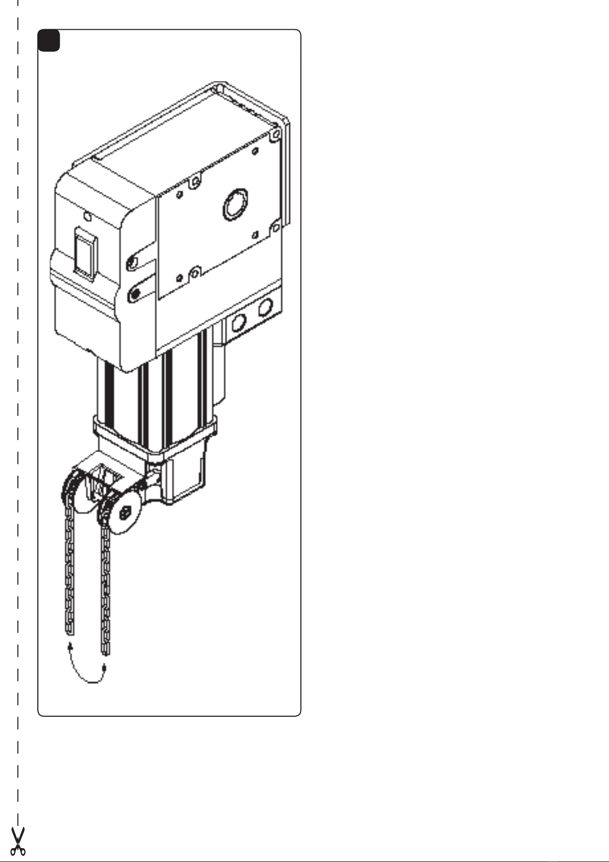
This geared motor has been studied and manufactured to activate bal-
anced sectional doors (POWER35).
Before proceeding to install the system, make sure that the door is bal-
anced and slides well. Check that the ropes, the springs and the para-
chuting system are in good conditions. For doors that have not been
installed recently, check also all the other parts subject to wear and tear.
The above instructions are essential for the safety of the system and the
reliability of the operator.
INSTALLATION
Thanks to its versatility, this geared motor can be assembled not only on
the right-side or left-side of the door, but also horizontally or vertically
(g. 2). The geared motor has been designed to directly activate the ca-
ble winding shaft of the door which must feature 1" diameter (25.4mm)
and should be provided of housing for the key. For cable winding shafts
having a dierent diameter, an adapter should be provided (itemVN.A30
for diam. 30 shafts, item VN.A3175 for diam. 31.75 shafts, item VN.A40
for diam. 40 shafts).To t the unit proceed as follows:
•Makesurethatthedistancebetweenthecablewindingshaftandthe
surface to which the bracket should be tted ranges between 82 and
150mm (as per g. 3).
•WeldortthebracketSwithscrewstothesurface.
•Insertthefearedmotorinthecablewindingshaft.
•TightenthescrewsinsertingthetighteningkeyCrst.
To calculate the movement speed of the door, proceed as follows:
V(door speed) = d(diam. of cable winding drum - m) x 3.14 x 24 = m/1'
It is possible to use the geared motor by extending the motion to the
rope winding-up shaft by means of a chain (item VN.RM). The motion
can possibly be transmitted reduced or multiplied (item VN.RV) (g. 4).
To calculate the movement speed of the door, proceed as follows:
V(door speed) = d(diam. of cable winding drum - m) x 3.14 x 24 x Z1 /
Z2 = m/1'
ADJUSTMENT OF THE LIMIT SWITCHES
The geared motor is equipped with 4 microswitches: 1 is the opening limit
switch (red cam), 1 the opening over-travel (blue cam), 1 closing limit
switch (yellow cam) and 1 is at disposal of the accessories (black cam),
N.C. max. 3A, 24Vac/dc max. To adjust the cams proceed as follows (g.
10):
•PutascrewdriverintheholeFtoavoidtherotationoftheshaft.
•LoosenthenutDtoallowrotationofthecamwithaveryreduced
resistance.
•Manuallymovethedooruntilitisalmostcompletelycloseandadjust
the yellow cam.
•Repeattheoperationwhileopeningthedoorandadjusttheredcam.
•Thenpositionthebluecamsothatitisactivatedslightlydelayedwith
respect to the red cam.
•Powertheautomaticunitandoperateit(ifitisaclosingoperation,invert
wires 1 and 3 of the motor power supply, g. 6 and 7) while adjusting the
closing cam (yellow) with slight adjustments as per g. 11.
•SlightlytightennutD.
Technical data POWER35
Power supply
Consumption
Power
Torque
* Door max. weight
Exit shaft hole
Max. force on Ø 120
Exit rounds
** L.S. reduction ratio
Jogging
Thermal switch trig.
Operat. temperature
Capacitor
Lubrication
Weight
Dimensions: see g.1
1x230V (50Hz)
3A
600W
90Nm
3700N
25.4mm
1500N
24rpm
1/20
30%
130°C
-20°C / +50°C
20µF
Agip Blasia 32
15kg
* For balancing doors and diameter Ø 120mm of the steel cable wind-
ing drum.
** Max. no. of rounds from the exit shaft.
10

.
VN.S
, .
.
,
.
e
(VN.S20/VN.ST20),
(VN.S40/VN.ST40)
.
. ,
.
,
.
.
,
,
(. 2).
1"(25.4
) .
(VN.
A30 Ø 30, VN.A3175 Ø 31.75, VN.A40 Ø 40).
:
· ,
, ,
82 150 ( . 3).
· ”S” .
· ,
”C”.
· ”V”.
:
V()= d( )x3.14x 24= /.
(VN.RM)
(VN.RV)(. 4).
:
V() = d( ) x 3.14 x 24 x Z1/ Z2
= /
P
4 : 1
( ), 1
( ), 1
( ) 1
( ), N.C.
. 3 A 24 .
(. 10):
· F.
· ”D” ,
.
·
.
·
.
· .
· ( ,
1 3, . 6 7),
() .
11.
· ”D”.
POWER35
* .
. Ø 120
**
: . . 1
1x230V (50Hz)
3A
600W
90Nm
3700N
25.4mm
1500N
24rpm
1/20
30%
130°C
-20°C / +50°C
20µF
Agip Blasia 32
15kg
*
Ø 120.
** . ..
11

POWER35
Vartotojo instrukcija - User’s handbook for the user -
Saugos taisyklės
Nestovėkite vartų judėjimo zonoje.
Neleiskite žaisti vaikams su valdymo įrenginiais ar prie vartų.
Sugedus įrenginiui, nebandykite jo remontuoti patys, o kreipkitės į
specialistą.
Rankinis arba avarinis darbo režimas
Dingus elektrai ar sugedus įrangai vartus galima darinėti rankomis
tokiu būdu (12 pav.):
1) patraukę abu grandinės galus į apačią, perjunkite vartus į rankinį
režimą.
2) darinėkite vartus grandine. Avarinis jungiklis rankiniame režime
automatiškai atjungia variklį.
3) norėdami vėl įjungti automatinį režimą patraukite lyną su žalia
rankena.
Priežiūra
Periodiškai tikrinkite įrangos darbą rankiniu ir automatiniu režimu.
Kad išvengtumėte nelaimingų atsitikimų, jokiu būdu nebandykite
įrangos remontuoti patys; tam kreipkitės į specialistą.
Vykdymo mechanizmui nereikia priežiūros, tik reikia periodiškai tikrinti
apsaugų ir kitų sistemos dalių, turinčių reikšmę saugiam įrangos
darbui, veikimą.
Perdirbimas
Nustojus naudoti gaminį reikia laikytis veikiančių teisinių aktų,
liečiančių įvairių dalių atskirą perdirbimą ir pakartotinį naudojimą
(metalai, plastmasės, elektros laidai ir t. t.); siūlome kreiptis į savo
montuotoją ar įmonę, turinčią teisę užsiimti tokia veikla.
Safety rules
Do not stand in the movement area of the door.
Do not let children play with controls and near the door.
Should operating faults occur, do not attempt to repair the fault but
call a qualied technician.
Manual and emergency operation
In the event of power failure or faults, the geared motor is equipped
with a safety device to open and close the door by hand.
To this purpose, to open/close the door use the chain shown in Fig.
14. A micro-switch automatically deactivates the motor as soon as the
manual operation starts.When the system is powered again, reset will
be performed automatically.
Maintenance
Every month check the good operation of the emergency manual
release. It is mandatory not to carry out extraordinary maintenance
or repairs as accidents may be caused.
These operations must be carried out by qualied personnel only.
The operator is maintenance free but it is necessary to check
periodically if the safety devices and the other components of the
automation system work properly. Wear and tear of some compo-
nents could cause dangers.
Waste disposa
l
If the product must be dismantled, it must be disposed according to
regulations in force regarding the dierentiated waste disposal and
the recycling of components (metals, plastics, electric cables, etc..).
For this operation it is advisable to call your installer or a specialised
company.
LIETUVIŲ
ENGLISH
.
.
/
, .
,
(. . A, B,C):
•открытьзащитнуюдверцумеханизмадеблокировки
(.A);
• вставить прилагаемый специальный ключ
90°, .
. ;
•теперьвозможнооткрывать/закрыватьвручную
;
•чтобы восстановить автоматическое
,
;
•удалитьрычагдеблокировки и закрыть защитную
.
•Периодическиконтролироватьэффективность
.
• Безусловно воздерживаться от попытки
/
/ ;
.
•Приводнетребуетповседневногообслуживания,
,
.
,
(, ,
);
..
12

14
13

Pos. POWER35
Apibūdinimas - Description - Code
1Variklio velenas Shaft
9686851
2Galinis jungiklis Limit switch
9686852
3Išėjimo velenas Output shaft
9686853
4Kabelių dėžutė Cable box
9686855
5Dangtelis Cover
9686856
IDOMUS UAB - Chemijos str. LT-51332, Kaunas, Lithuania - Tel. +370 37 308 900 - Fax +370 37 308 907
14
Table of contents
Other idomus Garage Door Opener manuals
Popular Garage Door Opener manuals by other brands

B&D
B&D Controll-A-Door 4 instructions

Automatic Technology
Automatic Technology GDO-6v3 EasyRoller installation instructions

CAME
CAME 801XC-0120 quick start guide

Johnson Controls
Johnson Controls HomeLink Operating Instructions and Programming Guidelines

Telcoma
Telcoma JAZZ INSTRUCTION HANDBOOK AND SPARE PARTS CATALOGUE

Chamberlain
Chamberlain 8550W user guide