AutomationDirect SOLO SLM Series User manual

3505 HUTCHINSON ROAD
CUMMING, GA 30040-5860
Quick Start Guide
Quick Start Guide
Quick Start Guid
eQuick Start Guide
Quick Start Guid
e
SOLO Modular Temperature Controllers
SLM Series
Specications
Input
Input Sensor Register Value Available Range
0 ~ 50mV linear voltage input 17 0 ~ 50mV
4 ~ 20mA linear current input 16 4 ~ 20mA
0 ~ 20mA linear current input 15 0 ~ 20mA
0 ~ 10V linear voltage input 14 0 ~ 10V
0 ~ 5V linear voltage input 13 0 ~ 5V
Platinum RTD (Pt100) 12 -200 ~ 600°C (-328 ~ 1,112°F)
Platinum RTD (JPt100) 11 -20 ~ 400°C (-4 ~ 752°F)
Thermocouple TXK type 10 -200 ~ 800°C (-328 ~ 1,472°F)
Thermocouple U type 9 -200 ~ 500°C (-328 ~ 932°F)
Thermocouple L type 8 -200 ~ 850°C (-328 ~ 1,562°F)
Thermocouple B type 7 100 ~ 1,800°C (212 ~ 3,272°F)
Thermocouple S type 6 0 ~ 1,700°C (32 ~ 3,092°F)
Thermocouple R type 5 0 ~ 1,700°C (32 ~ 3,092°F)
Thermocouple N type 4 -200 ~ 1,300°C (-328 ~ 2,372°F)
Thermocouple E type 3 0 ~ 600°C (32 ~1,112°F)
Thermocouple T type 2 -200 ~ 400°C (-328 ~ 752°F)
Thermocouple J type 1 -100 ~ 1,200°C (-148 ~ 2,192°F)
Thermocouple K type 0 -200 ~ 1,300°C (-328 ~ 2,372°F)
Note 1: Install the supplied 249 ohm resistor between terminal #1 and #2 for linear current inputs.
Note 2: Default setting: Pt100 input.
The range of linear input and feedback value is adjustable. Range of input feedback: -999 ~ 9,999. Take 0 ~ 20mA input as
example, -999 refers to 0mA input, and 9,999 refers to 20mA input. If we change the range to 0 ~ 2,000, 0 will refer to 0mA
input, and 2,000 will refer to 20mA input. 1 display scale = 0.01mA.
This Quick Start Guide provides basic information on setting up the SOLO SLM temperature
controllers. For advanced setup visit the AutomationDirect web site at www.AutomationDirect.com.
Specifications
Operating Voltage
Range 21.6 to 26.4 VDC
Power Consumption Rated 24 VDC, Max. 24 W combined, 3W + 3W x number of SLM2 controllers (Max. 7)
Input Sensors
Thermocouple: K, J, T, E, N, R, S, B, L, U, TXK
Platinum RTD: Pt100, JPt100
Linear DC input: 0 ~ 5V, 0 ~ 10V, 0 ~ 20mA, 4 ~ 20mA, 0 ~ 50mV
Sampling Rate Analog input: 0.15 sec. Thermocouple or platinum RTD: 0.4 sec.
Control Method PID, ON/OFF, Ramp / Soak control or Manual
Output Types
Relay: SPST, Max. load 250VAC, 3A resistive load
Voltage pulse: 12VDC, Max. output current: 40mA
Current: DC 4 ~ 20mA (Load resistance: < 500Ω)
Analog voltage: 0 ~ 10V (Load resistance: > 1,000Ω)
Output Function Control output, alarm output, retransmit output
Retransmit output is available only when output 1 is linear voltage or current output.
Alarm 12 alarm modes
Communication RS-485 communication, 2,400 bps ~ 38,400 bps
Communication
Protocol Modbus protocol, ASCII/RTU format
Vibration Resistance 10 ~ 55Hz, 10m/s2 for 10mins, each in X, Y and Z direction
Shock Resistance Max. 300m/s2, 3 times in each 3 axes, 6 directions
Ambient Temperature 0 to 50°C (32 to 122°F)
Storage Temperature -20 to +65°C (-4 to 149°F)
Altitude 2,000m or less
Ambient Humidity 35% ~ 85% RH (non-condensing)
Pollution Degree 2
Safety Information
WARNING! ELECTRIC SHOCK DANGER
1. The SLM series is an OPEN-TYPE device and therefore should be installed in an enclosure free of
airborne dust, humidity, and vibration. The enclosure should prevent non-maintenance sta from
operating the device (e.g. key or special tool is required to open the enclosure).
THIS CONTROLLER IS AN OPEN-TYPE TEMPERATURE CONTROLLER. MAKE SURE TO EVALUATE ANY DANGEROUS
APPLICATION IN WHICH A SERIOUS HUMAN INJURY OR SERIOUS PROPERTY DAMAGE MAY OCCUR.
1. Be sure to tighten terminals to the correct torque of 0.19 Nm. Use solid or twisted wire from 14AWG
to 28AWG.
2. Protect the controller from dust or foreign objects to prevent controller malfunction.
3. Do not modify or disassemble the controller.
4. Do not connect anything to the unused terminals.
5. Make sure all wires are connected to the correct polarity of terminals.
6. Do not install and/or use the controller in places subject to: (a) Dust or corrosive gases and liquid (b)
High humidity (c) Vibration and shock (d) EMI / RFI (e) high temperature.
7. Power must be turned o when wiring, installing or uninstalling expansion modules (SLM2), or
changing a sensor.
8. Be sure to use wires that match the thermocouple types when extending or connecting the
thermocouple wires.
9. Use wires with correct resistance when extending or connecting a platinum resistance thermometer
(RTD).
10. Keep the wire as short as possible when wiring a platinum resistance thermometer (RTD) to the
controller and route power wires as far as possible from load wires to prevent interference and
induced noise.
11. This controller is an open-type unit and must be placed in an enclosure away from high temperature,
humidity, dripping water, corrosive materials, airborne dust and electric shock or vibration.
12. Make sure power cables and signals from instruments are all installed properly before energizing the
controller, otherwise serious damage may occur.
13. To prevent electric shock, do not touch the terminals in the controller or try to repair the controller
when power is applied.
14. Use a soft, dry cloth to clean the controller. Do not use acid or alkaline liquids for cleaning.
15. This instrument is not furnished with a power switch or fuse. Therefore, if a fuse or power switch
is required, install the protection close to the instrument.
16. Note: This controller does not provide overcurrent protection. Use of this product requires that
suitable overcurrent protection device(s) must be added to ensure compliance with all relevant
electrical standards and codes. A suitable disconnecting device should be provided near the
controller in the end-use installation.
WARNING: To minimize the risk of potential safety problems, you should follow all applicable local
and national codes that regulate the installation and operation of your equipment. These codes
vary from area to area and it is your responsibility to determine which codes should be followed,
and to verify that the equipment, installation, and operation are in compliance with the latest
revision of these codes.
Equipment damage or serious injury to personnel can result from the failure to follow all applicable
codes and standards. We do not guarantee the products described in this publication are suitable
for your particular application, nor do we assume any responsibility for your product design,
installation, or operation.
If you have any questions concerning the installation or operation of this equipment, or if you
need additional information, please call us at 1-800-633-0405 or 770-844-4200.This publication is
based on information that was available at the time it was printed. At Automationdirect.com® we
constantly strive to improve our products and services, so we reserve the right to make changes
to the products and/or publications at any time without notice and without obligation. This
publication may also discuss features that may not be available in certain revisions of the product.
Product Support
•For product support, specications, and installation troubleshooting, a
complete User Manual can be downloaded from the On-line Documentation
area of the AutomationDirect web site.
•For additional technical support and questions, call our Technical Support
team @ 1-800-633-0405 or 770-844-4200..
AutomationDirect’s SOLO Modular units are a single loop temperature controller that can
control heating or cooling processes. Depending upon the particular model of controller, the
available outputs include relay, voltage pulse, linear voltage, or current. Available with twelve
selectable alarm types. SOLO Modular controllers have two control outputs that can be used
for control of a heating or cooling applications, alarm output, or for retransmitting the process
variable. Using both outputs for control output allows for both heating and cooling control or
two stage heating or two stage cooling control. There are four types of control modes: PID,
ON/OFF, RAMP/SOAK and Manual. SOLO Modular can accept various types of thermocouple
and RTDs as well as 0-10V or 4-20 mA anaolog input signals.
Other features include:
•Auto Tuning (AT) function with PID control
•DIN rail mountable
•LEDs for indication and diagnostics
•Easy conguration using SL-SOFT SOLO conguration software or Modbus
communications
•Selectable between °C and °F
•cULus and CE agency approvals
General Description
SOLO SLM
3
1
2

Alarm Output
Alarm Output
Mode Alarm Type Alarm Output Operation
0No alarm OFF
1
Alarm output will be enabled when the
temperature reaches upper and lower limits.
• Alarm will be enabled when the PV exceeds SV
+ AL-H or falls below SV – AL-L.
ON
OFF
AL-L SV AL-H
2
Alarm output will be enabled when the
temperature reaches the upper limit.
• Alarm will be enabled when the PV exceeds SV
+ AL-H.
ON
OFF
SV AL-H
3
Alarm output will be enabled when the
temperature reaches the lower limit.
• Alarm will be enabled when the PV falls below
SV – AL-L.
ON
OFF
AL-L SV
4• Alarm will be enabled when the PV is between
SV + AL-L and SV – AL-L.
ON
OFF
AL-L SV AL-H
5
Alarm output will be enabled when the
temperature reaches the absolute value of the
upper and lower limits.
• Alarm will be enabled when the PV exceeds
AL-H or falls below AL-L.
ON
OFF
AL-L AL -H
6
Alarm output will be enabled when the
temperature reaches the absolute value of the
upper limit.
• Alarm will be enabled when the PV exceeds
AL-H.
ON
OFF
AL-H
7
Alarm output will be enabled when the
temperature reaches the absolute value of the
lower limit.
• Alarm will be enabled when the PV falls below
AL-L.
ON
OFF
AL-L
8
Standby upper/lower limit alarm
• Alarm will be enabled when the PV reaches SV
and exceeds SV + AL-H or falls below SV –AL-L.
ON
OFF
AL-L AL -H
SV
9
Upper limit standby alarm
• Alarm will be enabled when the PV reaches SV
and exceeds SV + AL-H.
ON
OFF
SV AL-H
10
Lower limit standby alarm
• Alarm will be enabled when the PV reaches SV
and falls below SV – AL-L
ON
OFF
AL-L SV
11
Upper limit hysteresis alarm
• Alarm will be enabled when the PV exceeds SV
+ AL-H and disabled when the PV falls below
SV + AL-L.
ON
OFF
AL-H
AL-L
12
Lower limit hysteresis alarm
• Alarm will be enabled when the PV falls below
SV – AL-H and disabled when the PV exceeds
SV – AL-L.
ON
OFF
AL-H AL-L
Note: AL-H and AL-L include AL1H, AL2H, AL1L and AL2L. When Output 1 is set to Alarm Output, use AL1H (1024H) and AL1L
(1025H). When Output 2 is set to Alarm Output, use AL2H (1026H) and AL2L (1027H).
SLM series oers 12 alarm modes. See the alarm table below for a description of types of alarm.
90.0
3.0
60.03.4
25.2
4.0
3.0
1
2
3
4
5
6
7
8
9
10
3
11
12
13
90.0
3.0
60.03.4
25.2
4.0
3.0
1
2
3
4
5
6
7
8
9
2
10
SLM1
SLM2
[0.99]
[0.16]
[0.12]
[0.12
]
[3.54]
[0.13]
[0.13]
[0.12] [0.12]
[3.54]
[0.16]
[0.99]
[2.36]
[2.36]
5
4
Controller Dimensions
Dimensions
mm [in]
SLM1 SLM2
1RUN/STOP switch Wiring and
Model name
2Wiring and Model
name DIN rail clip
3DIN rail clip I/O terminals
4I/O terminals LED indicators
5LED indicators Mounting hole
6Mounting hole Specication
label
7Specication label Extension port
8Extension port Extension clip
9Extension clip DIN rail
10 DIN rail Extension port
11
RS-485
communication
port
N/A
12 Extension clip N/A
13 DC power input N/A
LED Display
1. When power is normal, POWER LED will be on.
2. After SLM is switched on, all LEDs will be on. The communication protocol will be displayed for one
second. See table below for LED values.
3. RUN LED is on when the controller is active.
4. ERROR LED is on when errors occur in input, memory or communication.
5. When an output is active, its corresponding output LED will be on.
6. AT LED ashes when PID parameters are being auto-tuned.
7. RX LED ashes when SLM receives communication signals. TX LED ashes when SLM sends out
communication signals. Communication protocol displayed on the LEDs after the power to the SLM
is switched on:
WARNING! ELECTRIC SHOCK DANGER
To prevent electric shock, do not connect AC
power to your device until all input and output
connections are completed.
Terminal Identication
7
For 4-20 mA sensor input
install supplied 249Ω resistor.
Install jumper when using
2-wire RTD
0 - 10 VDC 4 - 20 mA
2-wire RTD
Thermocouple (Tc) 3-wire RTD
Vinin
Input and Outputs (SLM1 & SLM2 Front Terminals)
Power Input (SLM1 Bottom Terminals)
RS-485 (SLM1 Bottom Terminals)
Sensor Input
1
2
3
4
5
6
7
8
9
+
+
-
-
DC 21.6 to 26.4
24V
0V
Tc
OUT2
OUT1
+
+
+
+
-
-
-
-
+
+
+
+
-
-
-
-
1
2
1
2
1
2
3
1
2
1
2
3
Box Contents and Unpacking Instructions
•Unpack the SOLO SLM temperature controller from its shipping carton. Included in the carton is
the temperature controller, a 249 ohm resistor, and this Quick Start Guide.
•Inspect all equipment for completeness. If anything is missing or damaged, immediately call the
AutomationDirect returns department @ 1-800-633-0405.
•• Inspect the part number to ensure the model received matches the output type required.
SLM Temperature
Controller
SLM
Quick Start
Guide
249 ohm
resistor
6
5
48
LED Baud Rate
2400 4800 9600 19,200 38,400
AT Off Off Off Off On
TX Off Off On On Off
RX Off On Off On Off
LED Parity
01 Off Off On
02 Off On Off
LED Modbus Format
Err Off On
LED Stop Bits
RUN Off On

RS-485 Communication
9
Address Setting Parameter R/W Description
1000H Present temperature
value (PV) R
Unit: 0.1 degree. Analog input: 1EU.
The read values below indicate the occurrence of
errors: 8002H: Temperature not acquired yet
8003H: Temperature sensor not connected
8004H: Incorrect sensor type
8006H: Unable to acquire temperature, ADC
input error
8007H: Unable to read/write the memory
1001H 0 Set point (SV) R/W Unit: 0.1 degree. Analog input: 1EU.
1002H 6,000 Upper-limit of temperature
range R/W The content shall not be bigger than the range.
Unit: 0.1°
1003H -200 Lower-limit of temperature
range R/W The content shall not be smaller than the range.
Unit: 0.1°
1004H 12 Input type R/W See the table in “Input” section.
1005H 0 Control method R/W 0: PID, 1: ON/OFF, 2: Manual, 3: RAMP/SOAK
1006H 0Control selection of
Output 1 R/W 0: Heating, 1: Cooling, 2: Alarm, 3: Retransmit
output
1007H 4 Control cycle of Output 1 R/W 0 ~ 99, 0: 0.5sec
1008H 4 Control cycle of Output 2 R/W 0 ~ 99, 0: 0.5sec (Invalid when the 2 outputs are
the same control.)
1009H 476 Proportional band value R/W 1 ~ 9,999, Unit: 0.1°. Analog input: 1EU
100AH 260 Integral Time R/W 0 ~ 9,999
100BH 41 Derivative Time R/W 0 ~ 9,999
100CH 0 Integral Offset R/W 0 ~ 1,000, Unit: 0.1%
100DH 0 PD Control Offset R/W
Offset compensation value for proportional control
(when I=0)
0 ~ 1,000, Unit: 0.1%
100EH 100 Proportion Band Coefcient R/W COEF setting when in dual control output
1 ~ 9,999, Unit: 0.01
100FH 0 Dead Band R/W Dead band setting when in dual control output
-999 ~ 9,999, Unit: 0.1° or 1EU
1010H 0 Hysteresis of Output 1 R/W 0 ~ 9,999, Unit: 0.1° or 1EU
1011H 0 Hysteresis of Output 2 R/W 0 ~ 9,999, Unit: 0.1° or 1EU
1012H 0 Output 1 Level R/W
Read/write output percentage of Output 1
Unit: 0.1%. “Write” is only applicable in manual
mode.
1013H 0 Output 2 Level R/W
Read/write output percentage of Output 2
Unit: 0.1%. “Write” is only applicable in manual
mode.
1014H 0Upper-limit regulation for
analog linear output R/W 1 scale = 2.8μA = 1.3mV
1015H 0Lower-limit regulation for
analog linear output R/W 1 scale = 2.8μA = 1.3mV
1016H 0 PV Offset R/W Temperature offset regulation value
-999 ~ +999, Unit: 0.1° or 1EU
1019H 10 Temperature Filter Range R/W Range of temperature lter: 1~100, unit: 0.1°C
101AH 8 Temperature Filter Factor R/W Setting range: 0~50
1020H 0 Alarm 1 R/W 0 = Alarm 1 is disabled.
1- 18 = Alarm type number
1021H 0 Alarm 2 R/W 0 = Alarm 2 is disabled.
1- 18 = Alarm type number
1023H 0Control selection of
Output 2 R/W 0: Heating, 1: Cooling, 2: Alarm
1024H 40 Alarm 1 High Limit R/W See “Alarm Output” section.
1025H 40 Alarm 1 low Limit R/W See “Alarm Output” section.
1026H 40 Alarm 2 High Limit R/W See “Alarm Output” section.
1027H 40 Alarm 2 Low Limit R/W See “Alarm Output” section.
102AH Read/write status R
Bit 0 = Not Used
Bit 1 = ALM2
Bit 2 = °C
Bit 3 = °F
Bit 4 = ALM1
Bit 5 = OUT2
Bit 6 = OUT1
Bit 7 = AT
102CH 0Positive/negative retransmit
output R/W 0: positive, 1: negative
102EH LED Status R
Bit 0 = RUN
Bit 1 = ERR
Bit 2 = O2
Bit 3 = O1
Bit 4 = RX
Bit 5 = TX
Bit 6 = AT
Bit 7 = Not Used
102FH Firmware version R V1.00 is indicated as 0x100
1030H 0Starting Ramp / Soak
Pattern R/W 0 ~ 7
1032H Current Step Time
Remaining in Seconds R 0 ~ 54000
1033H Current Step Time
Remaining in Minutes R 0 ~ 900
1034H Current Step Number R 0 ~ 7
Address Setting Parameter R/W Description
1035H Current Pattern Number R 0 ~ 7
1036H Ramp Set Point R Unit is 0.1 (°C or °F)
1037H 1,000 Upper limit of retransmit
output R/W 0 ~ 100% upper limit of analog output, Unit: 0.1%
1038H 0Lower limit of retransmit
output R/W 0 ~ 100% lower limit of analog output, Unit: 0.1%
1040H~
1047H 7 Last Step Number R/W 0 ~ 7 = The last step number of the pattern
1050H~
1057H 0 Additional Cycles R/W 0 ~ 199
1060H~
1067H 0 Next Pattern Number R/W 0 ~ 7 = Next pattern number
8 = There is no next pattern
1068H 1 Run/Stop setting R/W 0: Stop, 1: Run, 2: Program end, 3: Program hold
1069H
(Duplicate
Address)
0 Control selection of Output 1 R/W 0: Heating, 1: Cooling, 2: Alarm, 3: Retransmit
output
106AH
(Duplicate
Address)
0 Control selection of Output 2 R/W 0: Heating, 1: Cooling, 2: Alarm
1071H 1Network Address R/W 1 ~ 247
1072H 0 Modbus Protocol R/W 1: RTU, 0: ASCII
1073H 2 Baud Rate R/W 0 ~ 4: 2,400 ~ 38,400
1074H 1 Bit Length R/W 0: 8 bits, 1: 7 bits
1075H 1 Parity R/W 0: None, 1: Even, 2: Odd
1076H 1 Stop Bit R/W 0: 2 stop bits, 1: 1 stop bit
2000H~
203FH 0 Ramp / Soak SV R/W -999 ~ 9999
2080H~
20BFH 0 Ramp / Soak Time R/W 0 ~ 1500 (15 hours 0 minutes)
1. Supports transmission speed: 2,400, 4,800, 9,600, 19,200, 38,400 bps;
2. Communication protocol: Modbus ASCII/RTU;
3. Function code: 03H (read Max. 8 words in register), 06H (write 1 word into register), 01H
(read Max. 16 bits of data), 05H (write 1 bit into register).
0811H Temperature unit display 0:°F, 1: °C (Default)
0813H Read/write auto-tuning status 0: End (Default), 1: Start
0814H Run/Stop setting 0: Stop, 1: Run (Default)
0815H Program hold ag 1: Program hold
0816H Program stop ag 1: Program stop

Mounting Instructions
How to connect a maximum of 8 controllers (Using a SLM1 with up to 7 SLM2 units) by using DIN rail.
rail
SLM units
10
Copyright 2023, Automationdirect.com Incorporated/All Rights Reserved Worldwide
Notes
Other AutomationDirect Temperature Controllers manuals
AutomationDirect
AutomationDirect SOLO SL4824 Series User manual
AutomationDirect
AutomationDirect SOLO User manual
AutomationDirect
AutomationDirect SL4848-RR User manual

AutomationDirect
AutomationDirect SOLO SL4848 Series User manual
AutomationDirect
AutomationDirect SOLO SL4896 Series User manual
AutomationDirect
AutomationDirect SOLO Basic SLB4848 Series User manual
Popular Temperature Controllers manuals by other brands

Aqua Medic
Aqua Medic T 2001 CC Operation manual
Multi Channel Systems
Multi Channel Systems TC01 user manual
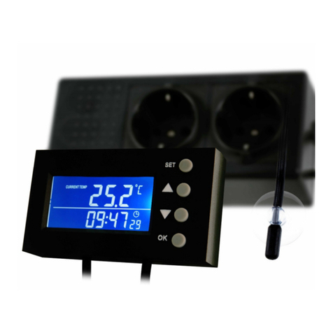
Aqua Medic
Aqua Medic T controller twin Operation manual

Lake Shore
Lake Shore DT-470-CU-HT installation instructions
red lion
red lion TMPJ2SU1 product manual
Prostat
Prostat PSPAC-WFMS installation instructions
