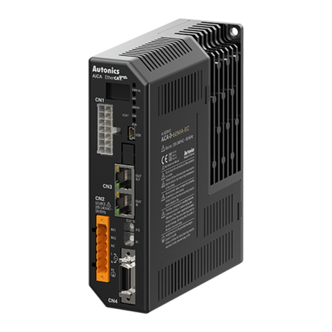
Autonics AiSA-D Series User manual

A-68
AiSA-D Series
-|Transparent setting guide|-
▣Features
AC Type 2-Phase Closed-Loop Stepper Motor Driver
● Brake operation for safe control of vertical load at power OFF and alarm occur. (Built-in brake type)
● Higher cost-eciency compared to servo motor drivers
● Torque control mode supported
● Able to check alarms and status with Alarm/Status display part (7 segment)
● Rapid response which is advantageous for the short distance continuous operation
● Able to implement Low frequency operation and high torque in low speed area
● Low current drive at middle.high speed area
● Max. stop torque at current down mode (available vertical load attaching)
● Easy to set various Gain with rotary switch
● Applicable to the precision equipment such as optical inspection equipment
with the features of maintaining torque in stop and having no micro vibration (hunting)
● Various resolutions
: 500, 1000, 1600, 2000, 3200, 3600, 5000, 6400, 7200, 10000 (10 steps)
● 10-levels of resolution setting
● Frame size 60mm, 86mm (Applied Motor: AiA-M Series)
● Filed requiring preciseness such as semiconductor equipment, 3D printer, optical inspection equipment, chip mounter,
cartesian robot, conveying equipment, and alignment stage.
▣Applications
Please read “Safety Considerations”
in the instruction manual before using.
▣Ordering Information
Series
Item
Category
Motor frame size
Motor axial length
Encoder resolutions
Brake
Ai 60D M A
60 60×60mm
86 86×86mm
No mark Standard type
BBuilt-in brake type
A10,000PPR(2,500PPR×4-multiply)
M48mm
L69mm
M60mm
L75mm
DDriver
AAC Power
S Standard
Ai Articial intelligence
S A
Power

A-69
AC Type 2-Phase Closed-Loop Stepper Motor Driver
SENSORS
FIELD
INSTRUMENTS
CONTROLLERS
MOTION DEVICES
SOFTWARE
(A)
Closed Loop
Stepper System
(B)
Stepper Motors
(C)
Stepper Motor
Drivers
(D)
Motion
Controllers
-|Transparent setting guide|-
▣Configuration Diagram
※ The thickness of cable should be same or thicker than the below specifications when connecting the cable for connector.
① CN1(motor+encoder connector): AWG22
② CN2(power connector): AWG18
③ CN3(I/O connector): AWG28
④ CN4(brake connector): AWG22
※ In case of unwanted noise generating from peripherals and power, use ferrite core in the wiring.
※ is sold separately.
-Connect Pin no. 1, 2 on power connector (CN2).
-Use in condition of the high inertia load or the short deceleration time.
-Forced cooling is required in condition of high surface temperature of regenerative resistance.
Model Specication Manufacture
IRC100 ● Resistance: 100Ω ±5%,
● Rated Power: 60W(standby), 100W(heatsink attached) Rara Electronics Corp.
Regenerative resistance
Protect the product from external noise and surge by connecting power.
※ Be sure to disconnect the surge protector when testing internal pressure.
It may result in porduct damage.
Model Specication Manufacture
LT-C12G801W
● Nomial discharge current: 2500A
● Max. discharge current: 5000A
● Voltage protection level: 1.5kV
OTOWA Electric Co. Ltd
Surge protector
-Connect the power to suppress external noise.
-The wires should be connected as short as possible and grounded.
Model Specication Manufacture
RNS-2006
● Rated voltage: 250V
● Rated current: 6A
● Max. leakage current: 1mA
Orient Electronics
Noise filter for power
-Connect to wiring to suppress external noise.
-Depending on frequency, filtered noise may different.
Model Specication Manufacture
Motor line, I/O signal line 28A5776-0A2 Lairdtech
Power line 28A5131-0A2
Noise filter for signal line
Noise filter
for signal line
Regenerative
resistance
RG1 CN2
RG2
Surge protector
Circuit
breaker
Noise filter
for power
I/O Terminal
CN3
AiA-M Series (motor)
CN1
AiSA-D Series
(motor driver)
200-240 VACᜠ
L
N
PE
PLC
CN4
※ is for built-in brake type only.
24 VDCᜡ

A-70
AiSA-D Series
-|Transparent setting guide|-
Model※1AiSA-D-60MA(-B) AiSA-D-60LA(-B) AiSA-D-86MA(-B) AiSA-D-86LA(-B)
Power
consumption
Power supply 200-240 VACᜠ 50/60 Hz
STOP※2Max. 60 W Max. 65 W Max. 70 W
Max. during operation Max. 160 W Max. 220 W Max. 250 W Max. 300 W
Max. Run current※32.0 A/Phase
Auxiliary
power※4
Power supply 24 VDCᜡ
Input current 0.3 A 0.5 A
STOP current 20 to 100% of max. RUN current
Rotation speed 0 to 3000 rpm
Resolution※5500 (factory default), 1000, 1600, 2000, 3200, 3600, 5000, 6400, 7200, 10000 PPR
Speed lter※50 (disable) (factory default), 2, 4, 6, 8, 10, 20, 40, 60, 80, 100, 120, 140, 160, 180, 200 ms
Motor GAIN※5Standard GAIN: 0 to F, Inertia GAIN: 0 to F
In-Position※5Fast Response: 0 (factory default) to 7, Accurate Response: 0 to 7
Pulse input method※51-pulse or 2-pulse input (factory default) method
Motor rotation direction※5CW (factory default), CCW
Status indicator ● Alarm/Status display part: orange LED 7 seg. ● Power/Alarm indicator: green/red LED
● In-Position indicator: orange LED ● Servo On/Off indicator: blue LED
I/O
Input
CW, CCW (Run pulse)
Servo On/Off (photocoupler input) - [H]: 24 VDCᜡ, [L]: 0-0.5 VDCᜡ,Pulse width - min. 1 ms
Alarm reset (photocoupler input) - [H]: 24 VDCᜡ, [L]: 0-0.5 VDCᜡ,Pulse width - min. 10 ms
Output ● Photocoupler: In-Position, Alarm out
● Line driver: encoder signal (phase A, A, B, B, Z, Z)
Operation mode Standard, Torque mode
Input pulse
specications
Pulse width CW, CCW: input pulse frequency duty 50 %,
Rising/Falling time CW, CCW: max. 0.5 ㎲
Pulse input voltage CW, CCW - [H]: 4-8 VDCᜡ, [L]: 0-0.5 VDCᜡ
Max. input pulse freq.※6CW, CCW: 500 kHz
Alarm Overcurrent, overspeed, position tracking, overload, overheat, motor connection, encoder connection,
overvoltage, undervoltage, motor misalignment, command pulse, in-position, brake
Input resistance 4.7 kΩ (Anode Pull-up)
Insulation resistance Over 200 MΩ (at 500 VDCᜡ megger)
Dielectric strength 1,500 VACᜠ 60 Hz for 1 min
Vibration 1.5 mm amplitude at frequency of 10 to 55 Hz (for 1 min) in each X, Y, Z direction for 2 hours
Shock 300 m/s2 (approx. 30 G) in each X, Y, Z direction for 3 times
Environment Ambient temp. 0 to 50 ℃, storage: -10 to 60 ℃
Ambient humi. 35 to 85 %RH, storage: 10 to 90 %RH
Protection structure IP20 (IEC standard)
Approval ᜢ
Weight※7● Standard type: Approx. 920 g (approx. 800 g)
● Built-in brake type: Approx. 1,020 g (approx. 780 g)
※1:
The model name indicates driver type. (none: standard type, B: built-in brake type)
E.g.) AiSA-D-60MA-B: built-in brake type stepping motor driver.
※2: Based on the ambient temperature 25 ℃, ambient humidity 55 %RH, and STOP current 20 %.
※3: RUN current varies depending on the input RUN frequency and max. RUN current at the moment varies also.
※4: Auxiliary power is only available in built-in brake type. Corresponding specification is not available in standared type.
※5:
Settings are available with the switches located on the front. When setting, the power must not be applied and cannot be set after
power is applied.
※6:
Max. input pulse frequency is max. frequency to be input and is not the same as max. pull-out frequency or max. slewing frequency.
※7: The weight includes packaging. The weight in parentheses is for unit only.
※Environment resistance is rated at no freezing or condensation.
▣Specifications

A-71
AC Type 2-Phase Closed-Loop Stepper Motor Driver
SENSORS
FIELD
INSTRUMENTS
CONTROLLERS
MOTION DEVICES
SOFTWARE
(A)
Closed Loop
Stepper System
(B)
Stepper Motors
(C)
Stepper Motor
Drivers
(D)
Motion
Controllers
-|Transparent setting guide|-
▣Dimensions
(unit: mm)
Panel cut-out
2-M5
37
150
126
47
37
150
160
▣Installation
※Install on the metal plate with high thermal conductivity for heat dissipation of the driver.
※Install in the well-ventilated area and install the cooling fan in the unventilated environment.
※ Failure to heat dissipation may result in damage or malfunction due to the stress on the product.
Check the environment of use within the rated specifications and install on the well-heat dissipated area.
※ In case of installing the drivers more than two,
keep distance at least 20mm in the horizontal direction and at least 25mm in the vertical direction.
(Unit: mm)
37 20
15025

A-72
AiSA-D Series
-|Transparent setting guide|-
▣Driver Status Indicators
Indicator &
Display part LED color Function Descriptions
PWR/ALM
Green Power indicator Turns ON when the unit operates normally after supplying power
Red Alarm indicator When alarm occurs, it flashes in various ways depending on the situation.
Refer to ' Control Input/Output → Output → 2. Alarm'.
INP Orange In-Position
indicator Turns ON when motor is placed at command position after positioning input.
SERVO Blue Servo On/Off indicator Turns ON when Servo is operating, turns OFF when servo is not operating.
Alarm/Status
display part Red Alarm, status indicator When alarm occurs, it displays number of the corresponding alarm and the
setting number of the rotary switches (RES/GAIN/INP)
▣Driver Setting
Function selection DIP switch
-Set rotation direction, pulse input method, motor gain and torque mode.
ON 1 2 3 4
No. Name Function Switch position
ON OFF (factory default)
1 DIR Rotation direction CCW CW
2 1P/2P Pulse input method 1-Pulse input method 2-Pulse input method
3 GS H/L Motor GAIN setting Inertia GAIN Standard GAIN
4 TM Torque mode Torque mode Standard mode
●STOP current
CW [H]
[L]
CCW [H]
[L]
Rotation angle
position CW CCW
Rotation angle
position CW CCW
[H]
[L]
[L]
[H]
CW
CCW
※ [H]: photocoupler ON (voltage of both ends 4-8VDC), [L]: photocoupler OFF (voltage of both ends 0-0.5VDC)
※
2-pulse input method
CW: forward rotation signal input
CCW: reverse rotation signal input
●Pulse input method
※
1-pulse input method
CW: rotation operation signal input
CCW: rotation direction signal input
([H]: forward rotation, [L]: reverse rotation)
-In order to decrease motor heat and current consumption at motor stopping moment (in case there is no input during the time of the double
width of last input pulse), set the stop current supplied to the motor phase.
2
3
4
6
11
10
1
5
13
12
7
8
9
▣Unit Descriptions
1. Alarm/Status display part (orange)
2. Power/Alarm indicator (PWR/ALM) (green/red)
3. In-Position indicator (INP) (orange)
4. Servo On/Off indicator (SERVO) (blue)
5. Function selection DIP switch
6. Resolution rotary switch (RES)
7. Motor gain setting rotary switch (GAIN)
8. Speed filter / Limit setting rotary switch (S.F)
9. In-Position setting rotary switch (INP)
10. Motor+Encoder connector (CN1)
11. Power connector (CN2)
12. I/O connector (CN3)
13. Brake connector (CN4) ※1
※1: Corresponding connector is for built-in brake type only.

A-73
AC Type 2-Phase Closed-Loop Stepper Motor Driver
SENSORS
FIELD
INSTRUMENTS
CONTROLLERS
MOTION DEVICES
SOFTWARE
(A)
Closed Loop
Stepper System
(B)
Stepper Motors
(C)
Stepper Motor
Drivers
(D)
Motion
Controllers
-|Transparent setting guide|-
RES: Resolution setting switch
-Set the resolution of driver.
-The number of pulses per 1 rotation by resolution is each 500, 1000, 1600, 2000, 3200, 3600, 5000, 6400, 7200, 10000.
-Modified setting values are not applied in the running status, and the values will be applied after motor stopped.
5
0
1
2
3
4
6
7
8
9
RES
Setting Pulse/Revolution Resolution Setting Pulse/Revolution Resolution
0(factory default) 500 2.5 5 3600 18
1 1000 5 65000 25
2 1600 87 6400 32
3 2000 10 87200 36
4 3200 16 910000 50
GAIN: Motor gain setting switch
-Depending on GS H/L switch setting, the motor GAIN sets High or Low.
-Motor GAIN is selectable from 32 GAIN.
- The larger gain is, the more improved transient response becomes and the less error occurs.
※
At the lowest system load status, raise the gain value until motor vibrates and set to 1 to 2 level lower.
S.F: Speed Filter / Limit setting switch
-Depending on TM switch setting, speed filter and speed limit function can be set.
● Speed Filter
-In standard mode, it sets the delay time between the command position and the motor position.
- It determines the responsiveness of the motor to the command and smoothly follows the speed even if the load changes or disturbance occurs.
● Speed Limit
-In torque mode, it sets the speed limit.
- When the rotation speed reaches the speed limit value, the torque control may become unstable. Set value greater than the speed to be limited.
8
0
4
C
6
E
2
A
1
9
3
B
D
5
7
F
GAIN
GS H/L OFF GS H/L ON
Setting Standard
GAIN Setting Standard
GAIN Setting Inertia
GAIN
0 ×1 8×9 0 ×17 8×25
1 ×2 9×10 1 ×18 9×26
2 ×3 A×11 2 ×19 A×27
3 ×4 B ×12 3 ×20 B ×28
4 ×5 C×13 4 ×21 C×29
5 ×6 D ×14 5 ×22 D ×30
6×7 E ×15 6×23 E ×31
7 ×8 F ×16 7 ×24 F ×32
8
0
4
C
6
E
2
A
1
9
3
B
D
5
7
F
GAIN
Speed Filter (TM OFF) Speed Limit (TM ON)
Setting Delay time Setting Delay time Setting Limit speed Setting Limit speed
0 Disable 860 ms 0 10 rpm 890 rpm
1 2 ms 980 ms 1 20 rpm 9120 rpm
2 4 ms A100 ms 2 30 rpm A150 rpm
36 ms B 120 ms 3 40 rpm B 200 rpm
48 ms C140 ms 4 50 rpm C250 rpm
5 10 ms D 160 ms 5 60 rpm D 300 rpm
620 ms E 180 ms 670 rpm E 380 rpm
7 40 ms F 200 ms 7 80 rpm F 500 rpm
Speed
GAIN
Proper
GAIN OverUnder
Status
INP: In-Position setting swtich
8
0
4
C
6
E
2
A
1
9
3
B
D
5
7
F
INP
Fast response Accurate response
Setting Value Setting Value
0
(factory default)
080
1 ±1 9±1
2 ±2 A±2
3 ±3 B ±3
4 ±4 C±4
5 ±5 D ±5
6±6E ±6
7 ±7 F ±7
In-Position
(fast response)
In-Position
(accurate response)
Time
Position
Delay time: 50ms
Command
position
Time
- After position command pulse has nished, if the gap between target position and real position is under In-Position setting value, positioning
completion pulse is output.
-Modified setting values are not applied in the running status, and the values will be applied after motor stopped.
<Graph for input speed
and motor response>
Delay time
Motor position
Input pulse
position
Time
Position

A-74
AiSA-D Series
-|Transparent setting guide|-
▣Driver Connectors
Connector function
● CN1: Motor+Encoder Connector
● CN3: I/O connector
8
9
13
………
………
147
6
2
1
Pin no. Function Pin no. Function
1 GND 8+5VDC
2 Encoder A 9Encoder A
3 Encoder B 10 Encoder B
4 Encoder Z 11 Encoder Z
5 PE 12 N.C
6Motor A 13 Motor B
7Motor A14 Motor B
1
……
……
11
10 20
Pin no. I/O Function Pin no. I/O Function
1 Input CW+ 11 Output In-Position+
2 Input CW- 12 Output In-Position-
3 Input CCW+ 13
-
N.C
4 Input CCW- 14
-
N.C
5 Input Servo On/O+ 15 Output Encoder A
6Input Servo On/O- 16 Output Encoder A
7 Output Alarm Out+ 17 Output Encoder B
8Output Alarm Out- 18 Output Encoder B
9Input Alarm Reset+ 19 Output Encoder Z
10 Input Alarm Reset- 20 Output Encoder Z
● CN2: Power connector
1
2
3
4
5
6
Pin no. Function
1Regenerative
resistance
2
3 N.C
4Power
5
6PE
Connector specifications
※Above connectors are suitable for AiSA-D Series.
Type Specications Manufacture
Connector Connector terminal Housing
CN1 Motor+Encoder 5557-14R 5556T
-
Molex
CN2 Power 5ESDVM-06P-OR
- -
Dinkle
CN3 I/O connector 10120-3000PE
-
10320-52F0-008 3M
CN4 Brake connector ESC250V-S2330704P
- -
Dinkle
Motor+Encoder cable
※ □ of model name indicates cable length (1, 2, 3, 5, 7, 10)
E.g.) C1DF14M-10: 10m moving type motor+encoder cable.
※It is recommended to use ferrite core at I/O cable and Motor+Encoder cable.
●Normal: C1D14M-□, Moving: C1DF14M-□
I/O cable
●CO20-MP□-R
(standard: AiS TAG)
※
□ of model name indicates cable length (010, 020).
For corresponding EMC standard, cable length should be below 2m.
E.g.) CO20-MP020-R: 2m I/O cable.
▣Sold Separately
Pin
no.
Function
(name tag)
Cable
color
Dot line color-
numbers
Pin
no.
Function
(name tag)
Cable
color
Dot line color-
numbers
1 CW+
Yellow
Black-1 11 In-Position+
White
Black-1
2CW- Red-1 12 In-Position- Red-1
3 CCW+ Black-2 13
-
Black-2
4 CCW- Red-2 14
-
Red-2
5 Servo On/O+ Black-3 15 Encoder A+ Black-3
6Servo On/O- Red-3 16 Encoder A- Red-3
7 Alarm Out+ Black-4 17 Encoder B+ Black-4
8Alarm Out- Red-4 18 Encoder B- Red-4
9Alarm Reset+ Black-5 19 Encoder Z+ Black-5
10 Alarm Reset- Red-5 20 Encoder Z- Red-5
● CN4: Brake connector
1
2
3
4
Pin no. Function
1 24 VDC
2 GND
3 Brake+
4 Brake-
※Corresponding connector is for built-in brake type only.

A-75
AC Type 2-Phase Closed-Loop Stepper Motor Driver
SENSORS
FIELD
INSTRUMENTS
CONTROLLERS
MOTION DEVICES
SOFTWARE
(A)
Closed Loop
Stepper System
(B)
Stepper Motors
(C)
Stepper Motor
Drivers
(D)
Motion
Controllers
-|Transparent setting guide|-
▣Contol Input/Output
Inner signal of all input/output consists of photocoupler.
ON, [H]: photocoupler power ON
OFF, [L]: photocoupler power OFF
3. Alarm Reset
-This signal is for clearing the alarm.
- Alarm reset signal maintains over 20ms as [H]
: Alarm is cleared, the alarm indicator and alarm output turns OFF, and the driver returns to normal status.
※
If the causes of the alarm are not removed, driver may not be returned to the normal status even with alarm reset.
※Refer to '4. Example of input circuit connection'.
2. Servo On/Off
-This signal is for rotating axis of motor using external force or used for manual positioning.
-Servo On/Off signal maintains over 1ms as [H]
: Regarded as Servo Off signal and phase current is cut to release torque.
The Servo ON indicator, the In-Position output and indicator turns OFF.
-Servo On/Off signal maintains over 1ms as [L]
: Regarded as Servo On signal and phase current is supplied to gain torque.
The Servo ON indicator, the In-Position output and indicator turns ON.
※Stop the motor for using the signal.
※Refer to '4. Example of input circuit connection'.
Input
1. Position command pulse
- Pulse input is selectable from 1-pulse input method and 2-pulse input method.
(Refer to ' SW1: Function selection DIP switch'.)
- When using extending cable, it is recommended to connect Common mode choke coil (2mH) to the CW, CCW terminal in series connection.
4. Example of input circuit connection
● Input pulse (CW, CCW)
-Use external power (VEX) 5 VDCᜡ in pulse input.
-When input power is exceeded, it may result the product damage.
-In case the external pulse input power (VEX) is over 5VDC, use external resistor RL.
-In case the external pulse input power (VEX) is over 12, 24VDC, refer to the RL as table below.
※RL= VEX-2.17V - 220Ω
0.011A
VCC RL
12VDC 680Ω(Min. 0.25W)
24VDC 1.7kΩ(Min.0.5W)
A. Differential line driver
-
+
2kΩ
220Ω
Driver
B. Open collector
-
+
2kΩ
220Ω
Driver
VEX
● External Input (Servo On/Off, Alarm Reset)
-Use external power (VEX) 24 VDCᜡ in external input Servo On/Off and Alarm Reset.
B. NPN circuit
-
+
10kΩ
Driver
VEX
Output
1. In-Position
-In-Position output is output condition of positioning completion signal.
- If the gap between target position and real position is under In-Position setting value after position command pulse has finished, In-Position
output turns to [H] and the In-Position indicator turns ON.
- In reverse, when the gap is over In-Position setting value, In-Position output turns to [L] and the In-Position indicator turns OFF.
-For accurate drive, check the In-Position output again and execute the next drive.
※Refer to '3. Example of output circuit connection'.
A. PNP circuit
-
+
VEX
10kΩ
Driver

A-76
AiSA-D Series
-|Transparent setting guide|-
No. of
ashing
Alarm/
Status Alarm type Descriptions Motor
stop
Maintain
torque
1E1 Overcurrent error When overcurrent flows at motor RUN element
O X
2E2 Overspeed error When motor speed is over 3,500rpm
3E3 Position tracking error When the gap between position command value and current position value
is over 90°
4E4 Overload error When applying load over the rated load for over 1 sec
5E5 Overheat error When heatsink temperature is over 90℃
6E6 Motor connection error When motor cable connection error occurs at driver
7E7 Encoder connection error When encoder cable connection error occurs at driver
8E8 Overvoltage error When input voltage is over 240VAC +10%
9E9 Undervoltage error※1When input voltage is under 200VAC -10%
10 EA Motor misalignment When motor is in misalignment
11 EB Command pulse error When input pulse is over 3,500rpm
When pulse is input before initial alignment
12 EC In-Position error When position error (over 1) is kept over 3 sec, after motor stopped.
13 ED Brake error When brake failed to operate.
2. Alarm
● Alarm
-This function stops motor to protect driver, depending on the error status such as overcurrent or overspeed.
-In case of normal status, output is [H], and in case of alarming status, output is [L].
-When supplying alarm reset, driver returns to the normal status.
※ Refer to '3. Example of output circuit connection'.
● Alarm/Status display
-When alarm occurs, the alarm indicator (ALM, red) flashes as the times of corresponding alarm type.
-The alarm/status display part displays the number of the corresponding alarm type.
0.4 sec 0.8 sec
1 12 23 3
※
1: When cutting off the power, the undervoltage error occurring is normal operation.
※
Depending on the alarm type, it flashes for 0.4 sec interval and it turns OFF for 0.8 sec repeatedly.
<E.g. case of alarm 3>
3. Example of output circuit connection
●External output signal ciruit
-Use external power (VCC) max. 30 VDC, 10mA for output.
-When current is over 10mA, use external resistor RL to control
current.
VF: LED forward voltage of primary photocoupler
●Encoder output signal circuit
-Encoder output signal uses a line driver (26C32).
-Connect the terminal resistance RL of 100 to 150Ω in parallel to
both ends (A, A, B, B, Z, Z) of each phase of encoder.
Differential line driver
+
-
RL
Driver
Open collector
+
-
10Ω RL
Driver
VCC
※RL = VCC-0.7V-VF - 10Ω
0.01A
▣Contol Input/Output
CW
※ It is recommended to use Line driver output
(corresponding to 26C32) at RECEIVER end of
encoder output and terminating resisters
(100-150Ω) in parallel at both ends of each phase
(A, A, B, B, Z, Z, corresponding to 26C31).
4. Encoder output waveforms
[H]
[H]
[H]
[H]
[H]
[H]
[L]
[L]
[L]
[L]
[L]
[L]
A
A
B
B
Z
Z
Clockwise (CW) ※T: 1 cycle of A, B phase
T
T
4
T
2±
T
2
T±
T
8
T
4±

A-77
AC Type 2-Phase Closed-Loop Stepper Motor Driver
SENSORS
FIELD
INSTRUMENTS
CONTROLLERS
MOTION DEVICES
SOFTWARE
(A)
Closed Loop
Stepper System
(B)
Stepper Motors
(C)
Stepper Motor
Drivers
(D)
Motion
Controllers
-|Transparent setting guide|-
▣Connection for Motor and Driver
※Index
: Input
: Output
: I/O
: N.C
2
1
3
L
N
PE
9
10
5
6
3
4
1
2
8
7
12
11
16
15
18
17
20
19
1
2
3
4
11
4
10
3
9
2
5
12
14
13
7
6
1
8
13
14
M
o
t
o
r
Motor
Encoder
E
n
c
o
d
e
r
CN1 CN4※1
CN3
CN2
A
A
B
B
A
A
B
B
Z
Z
+5VDC
GND
PE
N.C
Regenerative resistance
N.C
220Ω
220Ω
10kΩ
10Ω
10kΩ
10Ω
10kΩ
2kΩ
2kΩ
CW+
Brake+
CCW+
CCW-
CW-
Brake-
POWER
24VDCᜡ
Servo On/Off+
Servo On/Off-
Alarm Out+
Alarm Out-
In-Position+
N.C
In-Position-
N.C
Encoder A
Encoder B
Encoder Z
Encoder A
Encoder B
Encoder Z
Alarm Reset+
Alarm Reset-
Source
200-240VAC 50/60Hz
※1: Corresponding connector is for built-in brake type only.

A-78
AiSA-D Series
-|Transparent setting guide|-
● Follow instructions in 'Proper Usage'. Otherwise, it may cause unexpected accidents.
● Do not input CW, CCW signal at the same time in 2-pulse input method.
● When the signal input voltage is exceeded the rated voltage, connect additional resistance at the outside.
● To extend the motor+encoder cable, use the designated the cable.
● Keep the distance between power cable and signal cable more than 10cm.
● Install the unit vertically on the alarm/status display part upper side.
● For heat radiation of the driver, install a fan.
● Do not change any setting switches (function, resolution, motor gain, in-position switches) during the operation or after supplying power.
Failure to follow this instruction may result in malfunction.
● Do not input external signal until the driver is initialized (In-Position LED ON) after power is applied.
● Motor vibration and noise can occur in specic frequency period.
① Change motor installation method or attach the damper.
② Use and set the gain value.
● For using motor, it is recommended to maintenance and inspection regularly.
① Unwinding bolts and connection parts for the unit installation and load connection
② Strange sound from ball bearing of the unit
③ Damage and stress of lead cable of the unit
④ Connection error with motor
⑤ Inconsistency between the axis of motor output and the center, concentric (eccentric, declination) of the load, etc.
● This product does not prepare protection function for a motor.
● This unit may be used in the following environments.
① Indoors (in the environment condition rated in 'Specications')
② Altitude max. 2,000m
③ Pollution degree 2
④ Installation category II
▣Proper Usage
▣Troubleshooting
Malfunction Causes Troubleshooting
When motor does not
excite
Servo is not ON. Check that servo On/O input signal is [L].
In case of [H], servo is o and excitation of motor is released.
Alarm occurs. Check the alarm type and remove the cause of alarm.
When motor rotates to
the opposite direction of
the designated direction
Rotation direction setting is not correct. Check the DIR setting in the function selection DIP switch.
When motor drive is
unstable
Connection between motor and encoder is unstable. Check the Motor+Encoder connection cable.
Motor gain value is not correct. Check motor GAIN setting rotary switch (GAIN) value.
Other manuals for AiSA-D Series
2
This manual suits for next models
1
Table of contents
Other Autonics Servo Drive manuals
Popular Servo Drive manuals by other brands

CTB
CTB BKSC GNX Series operating manual

LICHUAN
LICHUAN MC856 Instruction book

Parker
Parker Compumotor TQ10 user guide

GFA ELEKTROMATEN
GFA ELEKTROMATEN ELEKTROMAT SI 100.24-55,00 installation instructions

Rockwell Automation
Rockwell Automation Allen-Bradley Kinetix 350 installation instructions

YASKAWA
YASKAWA S-V Series Safety precautions