AutoPatch AF-10 Assembly instructions

AF-10 and Stand-Alone Modules
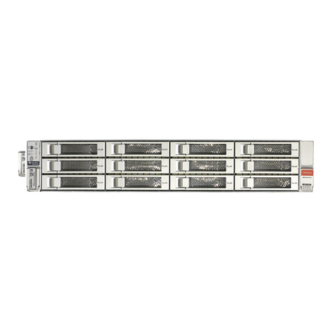
AF-10 Accessory Card Frame
/AF-10 Installation and Setup Guide
Distribution Amplifier (AF-10 & Modules)
/S-Video Distribution Amplifier Boards
/Standard Video DA Module (Modules Only)
/Wideband & Sync DA Modules (Modules Only)
Converters (AF-10 & Modules)
/DVI-D to RGBHV Converter Boards
/RGBHV to DVI-D Converter Boards
/MTP Multimode Fiber Boards (Modules Only)
CAT-5 / UTP Solutions (AF-10 & Modules)
/CatPro RGBHV Stereo (Modules Only)
/Video & Stereo CAT-5e/UTP Boards
/RGBHV over CAT-5 Boards
/CatPro Wiring Diagrams for Transmitter / Receiver Link Cable
/CAT-5 Wiring Diagrams for Transmitter / Receiver Link Cables
TCP/IP (Module Only)
/APWeb Server (with APWeb Supplement for the Interface)
Module Mounting Accessories
/Transmitter / Receiver Module Mounting Plate
/Module Rack Mounting Tray
/12-Box Rack Mount 4 RU Enclosure
May 2006


CAUTION
To avoid ESD (Electrostatic Discharge) damage to sensitive components, make
sure you are properly grounded before touching any internal materials.
When working with any equipment manufactured with electronic
devices, proper ESD grounding procedures must be followed to ensure
people, products, and tools are as free of static charges as possible.
Grounding straps, conductive smocks, and conductive work mats are
specifically designed for this purpose. Anyone performing field
maintenance on AutoPatch equipment should utilize an appropriate ESD
field service kit complete with at least a dissipative work mat with a
ground cord and a UL listed adjustable wrist strap with another ground
cord. These items should not be manufactured locally, since they are
generally composed of highly resistive conductive materials to safely
drain static charges, without increasing an electrocution risk in the event
of an accident. ESD protective equipment can be obtained from 3M™,
Desco®, Richmond Technology®, Plastic Systems®, and other such
vendors.
Installation and Setup Guide

Important Safety Information
and Instructions
When using and installing your AutoPatch product, adhere to the following basic safety
precautions. For more information about operating, installing, or servicing your
AutoPatch product see your product documentation.
äRead and understand all instructions before using and installing AutoPatch products.
äUse the correct voltage range for your AutoPatch product.
äThere are no user serviceable parts inside an AutoPatch product; service should only
be done by qualified personnel.
äIf you see smoke or smell a strange odor coming from your AutoPatch product, turn
it off immediately and call AutoAssist.
äTurn off and unplug an enclosure before adding or removing boards, unless otherwise
specified in that product’s documentation.
äTo avoid shock or potential ESD (Electrostatic Discharge) damage to equipment,
make sure you are properly grounded before touching components inside an
AutoPatch product.
äFor products with multiple power supplies in each unit, make sure all power supplies
are turned on simultaneously.
äUse surge protectors and/or AC line conditioners when powering AutoPatch
products.
äOnly use a fuse(s) with the correct fuse rating in your enclosure.
äMake sure the power outlet is close to the product and easily accessible.
äMake sure the product is on or attached to a stable surface.
äTurn off equipment before linking pieces together, unless otherwise specified in that
product’s documentation.
äFor safety and signal integrity, use a grounded external power source and a grounded
power connector.
Installation and Setup Guide

Information et directives
de sécurité importantes
Veuillez vous conformer aux directives de sécurité ci-dessous lorsque vous installez et
utilisez votre appareil AutoPatch. Pour de plus amples renseignements au sujet de
l’installation, du fonctionnement ou de la réparation de votre appareil AutoPatch, veuillez
consulter la documentation accompagnant l’appareil.
äLisez attentivement toutes les directives avant d’installer et d’utiliser les appareils
AutoPatch.
äLe voltage doit être approprié à l’appareil AutoPatch.
äLes appareils AutoPatch ne contiennent aucune pièce réparable par l’usager; la
réparation ne doit être effectuée que par du personnel qualifié.
äSi de la fumée ou une odeur étrange se dégagent d’un appareil AutoPatch, fermez-le
immédiatement et appelez le Service de soutien technique (AutoAssist).
äFermez et débranchez le boîtier avant d’ajouter ou d’enlever des plaquettes, à moins
d’indication contraire fournie dans la documentation du appareil.
äPour éviter les chocs ou les dommages éventuels causés à l’équipement par une
décharge électrostatique, veillez à ce le dispositif oit bien relié à la terre avant de
toucher les composantes se trouvant à l’intérieur d’un appareil AutoPatch.
äVeillez à ce que tous les blocs d’alimentation des appareils dotés de blocs
d’alimentation multiples dans chaque unité soient allumés simultanément.
äServez-vous de protecteurs de surtension ou de conditionneurs de lignes à courant
alternatif lorsque vous mettez les appareils AutoPatch sous tension.
äPlacez uniquement des fusibles de calibre exact dans les boîtiers.
äVeillez à ce que la prise de courant soit proche de l’appareil et facile d’accès.
äVeillez à ce que votre appareil AutoPatch soit installé sur une surface stable ou qu’il
y soit fermement maintenu.
äFermez toutes les composantes de l’équipement avant de relier des pièces, à moins
d’indication contraire fournie dans la documentation de l’appareil.
äPar mesure de sécurité et pour la qualité des signaux, servez-vous d’une source
d’alimentation externe mise à la terre et d’un connect d’alimentation mis à la terre.
Installation and Setup Guide

Notices
AutoPatch©2002, all rights reserved. No part of this publication may be reproduced,
stored in a retrieval system, or transmitted, in any form or by any means, electronic,
mechanical, photocopying, recording, or otherwise, without the prior written permission
of AutoPatch. Copyright protection claimed extends to AutoPatch hardware and software
and includes all forms and matters copyrightable material and information now allowed
by statutory or judicial law or here in after granted, including without limitation, material
generated from the software programs which are displayed on the screen such as icons,
screen display looks, etc. Reproduction or disassembly of embodied computer programs
or algorithms is expressly prohibited.
No patent liability is assumed with respect to the use of information contained herein.
While every precaution has been taken in the preparation of this publication, AutoPatch
assumes no responsibility for error or omissions. No liability is assumed for damages
resulting from the use of the information contained herein.
Further, this publication and features described herein are subject to change without
notice. The United States Federal Communications Commission has specified that the
following notice be brought to the attention of the users of this product.
Federal Communication Commission Radio Frequency Interference Statement:
“This equipment has been tested and found to comply with the limits for a Class A digital
device, pursuant to Part 15 of the FCC Rules. These limits are designed to provide
reasonable protection against harmful interference when the equipment is operated in a
commercial environment. This equipment generates, uses, and can radiate radio
frequency energy and, if not installed and used in accordance with the instruction
manual, may cause harmful interference to radio communications. Operation of this
equipment in a residential area is likely to cause harmful interference in which case the
user will be required to correct the interference at his own expense.
If necessary, the user should consult the dealer or an experienced radio/television
technician for additional suggestions. The user may find the booklet, How to Identify
and Resolve Radio-TV Interference Problems, prepared by the Federal Communications
Commission to be helpful.”
This booklet is available from the U.S. Government Printing Office, Washington, D.C.
20402, Stock N. 004-000-00345-4.
AF-10™, XNNet™, and XNConnect™ are trademarks of XNTechnologies, Inc.
Use shielded cables. To comply with FCC Class A requirement, all external data
interface cables and adapters must be shielded.
MS-DOS, Windows, and Windows95 are registered trademarks of Microsoft
Corporation.
3M, Desco, Richmond Technology, and Plastic Systems are all registered trademarks.
Neuron®and LonTalk®are registered trademarks of Echelon.
Installation and Setup Guide

AutoPatch
Statement of Warranty
AutoPatch, a division of XNTechnologies, Inc., Cheney, Washington,
warrantees that the products manufactured by AutoPatch will be free of defects
in materials and workmanship for the lifetime of the product, subject to the
following terms and conditions.
Terms and Conditions
1. AutoPatch products are under warranty for a period of five (5) years
following the original sales invoice date. The warranty period may be
extended to the life of the product provided the warranty card is filled out
and returned to AutoPatch. TO VALIDATE THE LIFETIME
WARRANTY: THE AutoPatch WARRANTY CARD MUST BE FILLED
OUT BY THE DEALER AND RECEIVED BY AutoPatch WITHIN
THIRTY (30) DAYS OF THE INSTALLATION OF EQUIPMENT BUT
NO LATER THAN ONE (1) YEAR FROM THE ORIGINAL SALES
INVOICE DATE. A warranty certificate will be returned to the dealer to
verify the warranty period.
2. This Limited Lifetime warranty covers AutoPatch products shipped on or
after October 1, 1997. The Limited Lifetime warranty applies to products
in the original installation only. If the product is moved to a different
installation, the Limited Lifetime warranty will no longer apply and the
product warranty will revert to the original warranty which covers a period
of five (5) years following the original sales invoice date.
3. The product lifetime is defined as the period of time from the original sales
invoice date to ten (10) years after AutoPatch ceases manufacturing the
product model.
4. Warranty repairs are accomplished by returning the subassembly to
AutoPatch for repair. If conditions do not permit this procedure, AutoPatch
will invoice new or reconditioned (at AutoPatch’s option) replacement parts
and ship them to the dealer or to the customer if so directed by written order
from the dealer. In that case the replacement will be billed to the customer
and the customer may return the failed subassembly within 30 days for
credit. See “AutoPatch Returns Policy” in this manual for replacement
policies and procedures.
Installation and Setup Guide
Warranty

5. AutoPatch’s liability and Buyer’s remedies under this warranty shall
be limited solely to repair, replacement, or credit, at AutoPatch’s
option.
6. The AutoPatch warranty does not apply to any AutoPatch product that has
been modified, repaired by an unauthorized agent, or improperly installed,
used, or maintained. AutoPatch shall not be liable under any circumstances
for consequential or incidental damages including, but not limited to, labor
costs or loss of profits arising in connection with the use of or inability to
use AutoPatch products.
7. AutoPatch will not be responsible for items damaged during shipment to or
from AutoPatch. The shipping carrier is responsible for items damaged
during shipment.
8. This warranty is exclusive and in lieu of any other warranty, expressed or
implied, including but not limited to any implied merchantability or fitness
for a particular purpose. The terms of this warranty are governed by the
laws of the state of Washington; certain other states restrict warranty
limitations. You may have rights that are not defined herein.
9. This warranty may not be modified except in writing by an authorized
AutoPatch officer.
Installation and Setup Guide
Warranty

Contents
Welcome
Installer’s Product Notes ........................................i
Terms to Know.................................................ii
Technical Support ..............................................iii
Chapter 1 – Unpacking
Rear of the AF-10 ............................................1-2
Chapter 2 – Placing and Installing
Site Recommendations .......................................2-1
Rack Mounting the AF-10 .....................................2-3
Chapter 3 – Adding and Connecting Accessory Boards
Adding Accessory Boards.....................................3-1
Connecting Accessory Boards.................................3-3
Appendix A – AutoPatch Service and Returns Policy
Service......................................................A-1
Replacement Policies and Procedures .........................A-2
Special Notice ...............................................A-3
Appendix B – Product Specifications
General .....................................................B-1
Index
Installation and Setup Guide

Welcome
Applicability Notice
The AF-10 Installation and Setup Guide documents information
pertaining to the AF-10, Order #40-10.
Installer’s Product Notes
The AF-10 is an accessory card frame system that holds up to sixteen
plug-in accessory boards. The accessory boards come in an assortment of
connector combinations for converting a variety of signals.
Installation and Setup Guide i
Welcome

Terms to Know
Before jumping into the technical details of this manual, you should be
familiar with the following terms:
AutoPatch Routing System
A collection of AutoPatch components including a Distribution Matrix or
Matrices with appropriate controller(s) and accessories. The components
of this system interact to provide a single routing solution.
breakaway
The act of switching any level other than level 0 (default level)
independent of the rest of the logical set.
Distribution Matrix (DM)
The hardware and software necessary to route any one of multiple source
signals to one or more destination devices. Multiple inputs cannot be
routed to a single output. Distribution matrices are also known as routing
switchers, routing matrices, and switching matrices.
ESD
Electrostatic Discharge (ESD) refers to electrical charges (such as static
electricity) that can damage sensitive components inside an enclosure.
The graphic to the left of this definition precedes every procedure where
ESD damage could occur if you are not properly grounded and not
handling components correctly (see the Caution page inside the front
cover of this guide for more details about ESD).
grouping
The process of defining an ordered set of literals to form a logical set.
This process includes defining levels and breakaways.
level
A subset of a logical set formed to facilitate the switching of a portion of
the logical set. For example, if a logical set is defined by grouping literal
inputs and outputs for video components R, G, B, H, V and stereo audio
components Al, Ar (audio left and right), then the video components
could be defined as Level 1 and the audio components as Level 2 to
switch them separately if desired. Moreover, additional levels can be
defined and each component can be included in multiple definitions. In
the example above, Al could be defined as Level 3 and Ar as Level 4.
This would allow for separate breakaway of the two audio components.
If the level is not defined in the switch command, it defaults to Level 0,
which switches the entire logical set.
literal input or output
The physical input, output, or control that is connected to the system by a
cable, wire, or other means.
ii Installation and Setup Guide
Welcome
Welcome

logical input
A logical set that consists entirely of literal inputs.
logical output
A logical set that consists entirely of literal outputs.
logical set
An ordered set of literals that are grouped together in order to be
considered a single entity and to be switched as a unit. The logical set
may consist of input, output, or control literals.
macro
A sequence of control and/or configuration commands stored by the
system, which can be invoked by the use of the Execute Macro
command. The command sequence may include timing between
commands.
preset
A snapshot of the characteristics (e.g., volume, configuration state) of an
arbitrary set of logical inputs or outputs. The states of these
characteristics can be recalled by the use of the preset command. Logical
inputs and outputs that are not included in the preset definition will not
change state. Presets are defined within the context of a virtual matrix.
virtual matrix (VM)
A collection of logical sets and their level definitions. Certain constraints
apply to the ways in which logical sets and/or their level definitions can
be combined to form virtual matrices. A virtual matrix allows multiple
enclosures to be treated as a single routing system. It allows a single
enclosure to be treated as though it contained multiple independent
routing systems.
Technical Support
AutoPatch provides technical support 24 hours a day, 7 days a week
(except for U.S. holidays). Before calling with a question, please consult
this manual and the individual board documentation inserted in the back.
If these documents cannot fully answer your question, have your serial
number (located on the rear of the card frame) ready and call your
authorized AutoPatch dealer or call AutoPatch AutoAssist at: (toll free
for U.S. and Canada) 800-622-0246 or (international) 509-235-2636.
You can also reach us through our web site: www.autopatch.com,or
e-mail our AutoPatch Technical Support Specialists at:
Installation and Setup Guide iii
Technical SupportApplicability Notice
Welcome

Unpacking
The AF-10 is shipped with one accessory card frame in each shipping
box. Each box contains one of each of the following items (invoices are
sent separately):
qPower cord (one per card frame)
qAF-10
The shipping boxes are marked as “Box #_ of _,” where the first blank is
the box number and the second blank is the total number of boxes in the
shipment. Box #1 contains several additional items:
qPacking list
qInstallation and Setup Guide (including information on the specific
boards in the accessory card frame)
qOther enclosure products
Unpacking Tips
qBefore fully unpacking the AF-10, examine the shipping box for any
signs of damage. If a box is partially crushed or any sides have been
broken open, notify the shipping agency immediately and contact
your AutoPatch Salesperson or Representative.
qOnce unpacking is complete, closely check the physical condition of
the accessory card frame.
qCollect all documentation and envelopes.
Note: AutoPatch is not responsible for damage caused by insufficient
packing during return shipment to the factory. Upon request, AutoPatch
will supply new shipping boxes at cost.
Installation and Setup Guide 1-1
Unpacking

1.1 Rear of the AF-10
The rear of the accessory card frame has a power connector, expansion
slots, and the serial number. Card frame accessory boards ordered with
the AF-10 will be installed before shipping .
The following segments briefly introduce the hardware on the rear of the
AF-10.
Board Options
A single accessory card frame can hold up to sixteen different accessory
boards. Some boards come with a board extraction handle at the bottom.
Expansion Slots
Additional accessory boards can be ordered for any of the board slots
that are empty. If you use the expansion slot with the serial number, we
recommend keeping the slot plate with the serial number with the system
for easy reference.
Power Connector
The power connector is located in the farthest left-hand slot on the rear
of the card frame. Plugging in the power cord turns on the accessory card
frame.
1-2 Installation and Setup Guide
Rear of the AF-10
VIDEO 2
VIDEO 1
VIDEO 2
VIDEO 1
120VAC/ 240VAC
25 Watt /2A Max.
Rear view of an AutoPatch AF-10 with a variety of boards
Optional accessory boards
Expansion slots
Power
connector
Unpacking
Optional board extractor handles

Placing and Installing
This chapter covers site recommendations and provides a step-by-step
procedure for installing an AF-10 in a rack.
2.1 Site Recommendations
When placing the accessory card frame, site recommendations should be
considered to reduce potential hazards in regards to environment, chassis
accessibility, cooling and airflow, and power.
General Hazard Precautions
The recommendations listed address potential hazards that are considered
common to most rack installations:
Elevated Operating Ambient Temperature
Consideration should be given to installing the equipment in an
environment compatible with the manufacturer’s maximum rated
ambient temperature. This precaution is advised because in a closed or
multi-rack assembly, the operating ambient temperature of the rack
environment may be greater than the ambient room temperature.
Caution: To protect equipment from overheating, do not operate in an
area that exceeds the maximum recommended ambient temperature of
104°F (40°C). To prevent airflow restriction, allow at least 3 inches
(7.6 cm) of clearance around the card frame openings for proper airflow.
Reduced Airflow
Installation of the equipment in a rack should be such that the amount of
airflow required for safe operation of the equipment is not compromised.
Caution: Avoid placing high heat-producing equipment directly above
or below the card frame. Card frames are designed to adequately
dissipate the small amount of heat they produce under normal operating
conditions; however, this design is defeated when high heat-producing
equipment is placed directly above or below the enclosure(s).
Installation and Setup Guide 2-1
Placing & Installing

Mechanical Loading
Mounting of the equipment in the rack should be such that a hazardous
condition is not achieved due to uneven mechanical loading.
Circuit Overloading
Consideration should be given to the connection of the equipment to the
supply circuit and the effect that overloading of circuits might have on
over current protection and supply wiring.
Reliable Earthing (Grounding)
Reliable earthing of rack-mounted equipment should be maintained.
Particular attention should be given to supply connections other than
direct connections to the branch circuit (e.g., use of power strips).
Caution: To avoid system damage, turn on all power switches in a
system at the same time. WE RECOMMEND ATTACHING ALL
POWER CORDS TO A SINGLE SURGE PROTECTOR AND/OR AN
AC LINE CONDITIONER.
2.2 Rack Mounting the AF-10
The AF-10 can be mounted in a standard EIA 19 in. (48.26 cm) rack. To
hold the accessory card frame in place, rack installation ears are attached
prior to shipping.
Tools for installation in a rack:
qScrewdriver
qScrews that fit your rack [for mounting the card frame]
qAF-10
qStandard EIA 19 in. (48.26 cm) rack [an AF-10 is
3 RU tall and 10.4 in. (26.4 cm.) deep]
qSurge protector(s) – highly recommended
To install an AF-10 in a rack:
1. Place the AF-10 in the rack and attach front-mounting screws to hold
it firmly in place (repeat for each accessory card frame). It is often
easiest to install the top card frame (or enclosure) first and move
down from there.
2-2 Installation and Setup Guide
Placing and Installing
Placing & Installing

Note: Adjustments may need to be made for the length of the cable as
cabling/wiring is done. Check the Board Installation Guide(s) in the
back of this manual for details.
2. Attach the cables/wires to the connectors on the rear of the card
frame per the instructions in the Board Installation Guide(s) (in the
back of this manual) for specific accessory boards.
3. Attach the power cord to each card frame. Plugging in the power
cord turns on the accessory card frame. WE RECOMMEND USING
SURGE PROTECTORS AND/OR AN AC LINE CONDITIONER.
Installation and Setup Guide 2-3
Rack Mounting the AF-10
Placing & Installing
Rack installation of an AF-10

Adding and Connecting
Accessory Boards
The AF-10 is specifically built for adding accessory boards to expand a
system’s capabilities.
3.1 Adding Accessory Boards
You may need to adjust the board to compensate for the length of the
cable, if the length does not match the length specified for the factory
default setting. Make any necessary adjustments before adding the board
to the accessory card frame. See the specific Board Installation Guide in
the back of this manual for instructions.
Warning: To avoid ESD (Electrostatic Discharge) damage to sensitive
components, make sure you are properly grounded (see the Caution page
inside front cover) before handling any internal AF-10 materials.
Each accessory board has its own board extractor handle for ease of
installation.
To add an accessory board:
1. Unplug the card frame.
2. Remove the plate that covers the empty board expansion slot.
Installation and Setup Guide 3-1
Adding & Connecting
Accessory Boards
VIDEO 2
VIDEO 1
VIDEO 2
VIDEO 1
Remove the plate that covers the empty board slot

3. Line up the accessory board with the board guides that are on the top
and bottom of the board slot. With the board extractor handle in the
down position, carefully push the board firmly into the slot. When
the board is almost in, the extractor handle will start to lift. At this
point, flip the extractor handle up to snap the board into place.
4. Insert the screws into the holes on the connector assembly and
tighten the screws until they are snug.
To remove an accessory board, reverse the process. Remove screws,
push down on the board extractor handle, and pull the board out.
3-2 Installation and Setup Guide
Adding and Connecting Accessory Boards
VIDEO 2
VIDEO 1
VIDEO 2
VIDEO 1
Line up accessory board with the guides
and push firmly into position
VIDEO 2
VIDEO 1
VIDEO 2
VIDEO 1
Insert and tighten screws until they are snug
Adding & Connecting
Accessory Boards

3.2 Connecting Accessory Boards
Each Board Installation Guide in the back of this manual includes
directions for connecting to a specific model of accessory board’s
connectors.
Installation and Setup Guide 3-3
Connecting Accessory Boards
Adding & Connecting
Accessory Boards
Table of contents

