Autopilot Kanardia User manual

Autopilot — Installation Manual
Kanardia d.o.o.
November 2020
Revision 2.1


Autopilot Installation Manual
Contact Information
Publisher and producer:
Kanardia d.o.o.
Lopata 24a
SI-3000
Slovenia
Tel: +386 40 190 951
Email: info@kanardia.eu
A lot of useful and recent information can be also found on the Internet. See
http://www.kanardia.eu for more details.
Copyright
This document is published under the Creative Commons, Attribution-Share-
Alike 3.0 Unported licence. Full license is available on http://creativecommons.
org/licenses/by-sa/3.0/legalcode web page and a bit more human read-
able summary is given on
http://creativecommons.org/licenses/by-sa/3.0/. In short, the license
gives you right to copy, reproduce and modify this document if:
you cite Kanardia d.o.o. as the author of the original work,
you distribute the resulting work only under the same or similar license
to this one.
Credits
This document was written using TeX Live (L
A
T
E
X) based document creation
system using Kile running on Linux operating system. Most of the figures were
drawn using Open Office Draw, Inkscape and QCad applications. Photos and
scanned material was processed using Gimp. All document sources are freely
available on request under the licence mentioned above and can be obtained
by email. Please send requests to info@kanardia.eu.
Revision History
The following table shows the revision history of this document.
3
©
Kanardia 2016-2020

Autopilot Installation Manual
Revision Date Description
1.0 Aug 2015 Initial release.
1.1 Maj 2016 Tuning notes were added.
1.2 Jul 2016 Tuning table expanded.
2.0 Feb 2020 Complete Manual rework.
2.1 Nov 2020 Updated for changes in software version 3.8,
Amigo and Nesis/Aetos windows.
4
©
Kanardia 2016-2020

Autopilot Installation Manual CONTENTS
Contents
1 Introduction 8
1.1 Designations ............................ 8
1.2 IntendedUse ............................ 8
1.3 Operation Limitations . . . . . . . . . . . . . . . . . . . . . . . 9
1.4 Minimal Configuration . . . . . . . . . . . . . . . . . . . . . . . 9
1.4.1 Nesis/Aetos Based Minimal System . . . . . . . . . . . 10
1.4.2 Horis/Emsis Based Minimal System . . . . . . . . . . . 10
1.5 Principle of Operation . . . . . . . . . . . . . . . . . . . . . . . 11
2 Mechanical Installation 11
2.1 ServoMotor............................. 12
2.2 ServoArm.............................. 13
2.3 ServoArmLimiter......................... 13
2.4 Servo Arm Safety Pin . . . . . . . . . . . . . . . . . . . . . . . 14
3 Electrical Installation 14
3.1 ElectricalPower .......................... 14
3.2 CANBus .............................. 15
3.3 External Push Button . . . . . . . . . . . . . . . . . . . . . . . 15
3.3.1 Autopilot Quick Disconnect . . . . . . . . . . . . . . . . 16
3.3.2 Autopilot Level . . . . . . . . . . . . . . . . . . . . . . . 16
3.4 JoyuCommandStick........................ 16
4 Configuration 16
4.1 Overview .............................. 17
4.2 AutopilotSettings ......................... 17
4.2.1 Servo Configuration . . . . . . . . . . . . . . . . . . . . 18
4.2.2 GroundTest ........................ 20
4.2.3 Operation Limits . . . . . . . . . . . . . . . . . . . . . . 21
4.2.4 Controller Parameters . . . . . . . . . . . . . . . . . . . 23
4.2.5 Tuning............................ 24
5
©
Kanardia 2016-2020

Autopilot Installation Manual CONTENTS
5 Tuning 26
5.1 Controller.............................. 26
5.1.1 PIDcontroller ....................... 26
5.2 Step Change and Response . . . . . . . . . . . . . . . . . . . . 27
5.3 CascadeController......................... 28
5.4 Controller Problems . . . . . . . . . . . . . . . . . . . . . . . . 28
5.4.1 Backlash........................... 29
5.4.2 Slip ............................. 29
5.5 TuningProcedure.......................... 29
5.5.1 On-Ground ......................... 29
5.5.2 In-Flight........................... 30
5.6 TuningRules ............................ 30
6 In-Flight Tuning 31
6.1 Elevator............................... 31
6.1.1 Pitchtuning ........................ 32
6.1.2 Vertical speed tune . . . . . . . . . . . . . . . . . . . . . 36
6.2 Ailerontune............................. 39
6.2.1 Rolltune .......................... 39
6.2.2 Headingtune ........................ 40
6.3 Finetuning ............................. 41
6.3.1 Roll feed forward . . . . . . . . . . . . . . . . . . . . . . 41
6.3.2 Motorpower ........................ 42
7 Quick Configuration 42
7.1 ConfigureServos .......................... 43
7.2 DirectionTest............................ 43
7.3 OperatingLimits.......................... 43
7.4 Tuning................................ 44
8 Safety Measures 44
8.1 Automatic Disable . . . . . . . . . . . . . . . . . . . . . . . . . 45
8.2 ManualDisable........................... 45
8.3 Electrical Disable . . . . . . . . . . . . . . . . . . . . . . . . . . 46
8.4 Mechanical Disable . . . . . . . . . . . . . . . . . . . . . . . . . 46
6
©
Kanardia 2016-2020

Autopilot Installation Manual CONTENTS
A Autopilot Installation And Tuning Form 47
B Parameters For Known Airplanes 48
B.1 EkolotTopaz ............................ 48
B.2 PipistrelSinus ........................... 48
B.3 Aeropilot Legend 540 . . . . . . . . . . . . . . . . . . . . . . . . 49
B.4 Evector Eurostar EV97 . . . . . . . . . . . . . . . . . . . . . . 49
B.5 Aerospool Dynamic WT9 . . . . . . . . . . . . . . . . . . . . . 50
B.6 RokoAviation ........................... 50
B.7 Aeroprakt.............................. 51
B.8 DirectFly.............................. 51
B.9 ComcoIkarus............................ 52
7
©
Kanardia 2016-2020
Autopilot Installation Manual 1. Introduction
1 Introduction
First of all, we would like to thank you for purchasing our product.
This chapter describes the basic principle on which autopilot operates. After
reading it, you will be familiar with basic knowledge you will need to properly
install and tune the autopilot.
CAUTION: The autopilot is not TSO approved as a flight instrument.
1.1 Designations
A few icons appear on the side of the manual, which have special meanings:
This icon denotes information that needs to be taken with special
attention.
This icon denotes background information about the subject.
This icon denotes a tip.
In the text, Shall & Should appear frequently.
Shall . . . the use of this term indicates a requirement!
Should . . . the use of this term indicates a characteristics that is not required,
but it is highly recommended.
1.2 Intended Use
The autopilot is designed to help a pilot in stable, controllable flight conditions
during cruising. If such conditions are met, the autopilot can be engaged to
take some relief from the pilot, who can perhaps focus a bit more on ATC
communication or to do some navigation task. Nevertheless, it is still pilot’s
responsibility to monitor the autopilot and airplane behavior all the time.
8
©
Kanardia 2016-2020

Autopilot Installation Manual 1.3 Operation Limitations
1.3 Operation Limitations
Always respect the following limitations.
The autopilot shall be only used in VFR (Visual Flying Rules) condi-
tions.
Information from the Aircraft Operating Handbook always supersedes
information given in this manual.
The autopilot is designed to be used only in cruising conditions. It will
not work at low and high speeds. It can’t fly approaches and departures
and it can’t do takeoffs and landings.
The autopilot shall not be used in turbulence.
Do not use the autopilot with flaps extended.
In any case of abnormal activity, the autopilot must be deactivated and
the pilot must take over the commands immediately. Never wait for
autopilot to deactivate itself automatically.
Autopilot does not use any information from Magu (magnetic compass).
1.4 Minimal Configuration
Most modern light airplanes can be controlled during a stable flight by con-
trolling elevator and aileron only. An autopilot function can be achieved using
the following minimum configuration:
Two servo motors that are mechanically connected with the airplane
command system. One motor controls elevator and the other controls
aileron.
An AD-AHRS-GPS device which consists of many sensors and provides
crucial information required by the autopilot system (airspeed, rate of
climb, pitch, roll, position, direction, altitude, etc.) Such device is inside
one of our PDF instruments, for example, Nesis PFD, Aetos PFD, Horis
PFD or Emsis PFD.
A display unit takes pilot inputs like required altitude and direction. It
is also used to enter configuration parameters required to properly setup
the autopilot system.
9
©
Kanardia 2016-2020

Autopilot Installation Manual 1.4 Minimal Configuration
A servo motor controller. It monitors the pilot instructions and informa-
tion obtained from the sensors and controls the servo motor accordingly.
A communication system that connects all devices and allow information
exchange in real time.
In Kanardia autopilot case, there are two different solutions for an autopilot
minimal system.
1.4.1 Nesis/Aetos Based Minimal System
When Nesis or Aetos is used as a base, the following minimal equipment is
required for a fully functional autopilot:
Two SERU servo motors. SERU consists of a servo motor and an in-
tegrated controlling unit, which serves as a motor driver. One SERU
controls elevator and the other controls aileron.
Nesis III (or Aetos) PFD. The display has integrated AD-AHRS-GPS
device, which provides all sensor data. The display has several buttons
and a knob that allow pilot control over the system. In addition, touch
screen can be also used on Nesis III.
Simple RJ45 cables (a.k.a. Ethernet cables) are needed to connect them
together. The devices are communicating using the CAN bus system,
which is integral part of almost all Kanardia devices.
In this combination Amigo is optional, but recomended nevertheless.
1.4.2 Horis/Emsis Based Minimal System
When Horis or Emsis is used as a base, the following minimal equipment is
required for a functional autopilot:
Two SERU servo motors. SERU consists of a servo motor and an in-
tegrated controlling unit, which serves as a motor driver. One SERU
controls elevator and the other controls aileron.
Horis 80/57 (or Emsis 80/3.5“) PFD unit with integrated AD-AHRS-
GPS device, which provides all sensor data.
Amigo display, which acts as a command panel for the autopilot.
10
©
Kanardia 2016-2020

Autopilot Installation Manual 1.5 Principle of Operation
Simple RJ45 cables (a.k.a. Ethernet cables) are needed to connect them
together. The devices are communicating using the CAN bus system,
which is integral part of almost all Kanardia devices.
In this combination, Amigo is essential.
1.5 Principle of Operation
When autopilot is active, pilot selects requested altitude, direction and rate of
climb or descend. AD-AHRS-GPS device provides current values for almost
all flight parameters. Controller units compare the requested values with
actual values and give appropriate commands to the servo motors. The PID
controller principle is used together with the cascade control system.
The autopilot drives two separate controls: aileron and elevator. In general
these two controls are independent, though minor dependency may exists.
Each control has two control loops1. Elevator control has pitch loop and
vertical speed loop. The two loops are regulated by cascade. This means that
requested altitude sets wanted vertical speed and the vertical speed loop sets
wanted pitch. The pitch loop then controls the elevator by minimizing the
difference between requested and actual pitch. Aileron works in a similar way.
Requested direction sets the required roll angle and the roll loop controls the
aileron trying to minimize the difference between requested and actual roll
angle.
This means that autopilot has four loops: pitch and vertical speed loops are
used for elevator, while heading and roll loops are used for aileron. All these
loops must be properly tuned to achieve requested autopilot operation. Var-
ious experimental values in the form of tuning parameters are provided at
the end of the document. These values represent good starting point for first
autopilot tests.
2 Mechanical Installation
This section provides information about the installation of autopilot servo mo-
tors (the SERU device) into an airplane. It contains important rules which
1The control loop is basic term from control theory. In simple terms – the control
loop tries to move the actuator in such a way that difference between WANTED and
ACTUAL value becomes minimal.
11
©
Kanardia 2016-2020
Autopilot Installation Manual 2.1 Servo Motor
must be obeyed to have a working and safe autopilot system. The installa-
tion information in this section is extremely important and must be clearly
understood by the installer.
Improper servo installation or failure to observe and diagnose installation
problems prior to flight can result in extremely serious consequences, including
loss of ability to control the aircraft. If there are any questions on the part
of the installer it is mandatory to resolve these questions prior to flight of the
aircraft.
CAUTION: Improper installation could result in lost aircraft controls,
injury or death!
2.1 Servo Motor
The servo motor must be installed in a fixed position. It must be attached with
all four mounting screws. The motor mount should be provided by aircraft
manufacturer and has to be adapted to specific airplane model. The motor
should be oriented parallel with longer edge regarding control rod connected
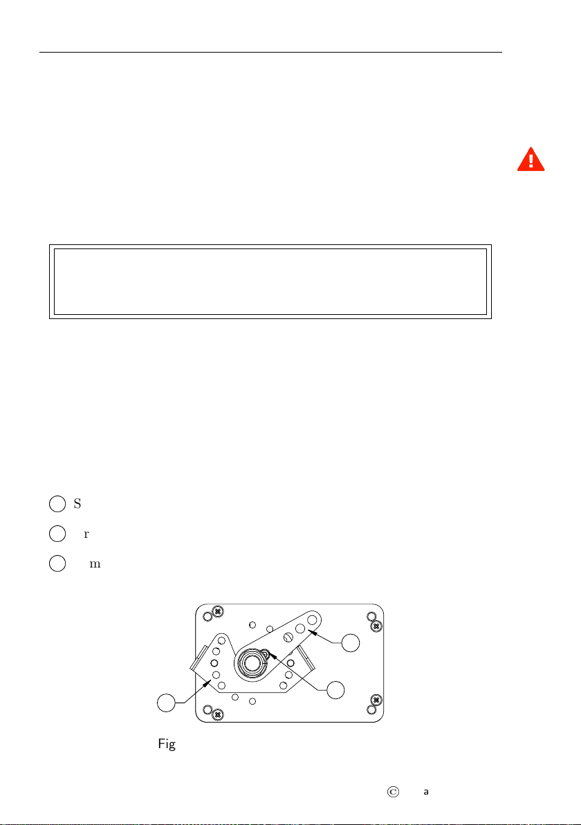
to the servo arm. The servo schematics is given in Figure 1. It defines three
important elements:
1
O
Safety pin,
2
O
Arm movement limiter,
3
O
Arm.
1
2
3
Figure 1: Safety pin, limiter and arm.
12
©
Kanardia 2016-2020

Autopilot Installation Manual 2.2 Servo Arm
2.2 Servo Arm
Servo arm has multiple holes for mounting control rod. The hole in use should
be chosen to maximize the arm rotation. Servo arm should not be removed or
replaced without Kanarida advise. The removal of servo arm includes removal
of safety pin. Please contact Kanarida before replacing safety pin for latest
instructions.
Extreme command position
150° or less!
90° is ideal case for
neutral command position
Extreme command position
30° or more!
Figure 2: Main servo dimensions.
Figure 2 illustrates valid relative positions between command rod and servo
arm. When command is in neutral position, the angle between rod and arm
shall be 90◦or at least very close to this ideal case. When command is in
its extreme position the angle between the command rod and the arm must
never be more than 150◦or less then 30◦.
Under no circumstances the servo arm is allowed to come into position called
over center – the position at which the primary aircraft control would lock up
and can result in fatal crash. A mechanical stops must be applied to prevent
this to happening. Mechanical stops must limit the arm movement at least
30◦before the over center situation.
2.3 Servo Arm Limiter
To protect against control lock up, a mechanical arm limiter is supplied with
servo. The limiter is drilled so that it can be mounted at different angles as
required (18◦intervals).
The limiter must not prevent aircraft command movements. Always make
sure that the controls can have their full travel and they never reach the servo
limiter.
13
©
Kanardia 2016-2020
Autopilot Installation Manual 2.4 Servo Arm Safety Pin
2.4 Servo Arm Safety Pin
Safety pin is a safety mechanism which prevents blocking of the aircraft com-
mand system for the case of blocked servo motor. If servo blocks the command
system, pilot must apply high force on the command stick. This force will
break the pin and release the servo from command system. Once the pin is
broken, the autopilot system is not operational until the pin is replaced.
If safety pin is broken or it gets slack the whole autopilot system must be
checked. Only after the cause of the problem was found and corrected, safety
pin can be replaced with a new pin. Always use original safety pin.
The safety pin is made from high grade steel and it is intentionally weaken to
break at specific torque applied on servo arm.
The airplane command system must be capable to withstand the forces in the
command system required to break the safety pin.
3 Electrical Installation
Servo motor has two electrical connections. The first one provides power for
the electrical motor and the second one connects controlling device with the
CAN bus. (The controlling device is hidden inside the servo motor).
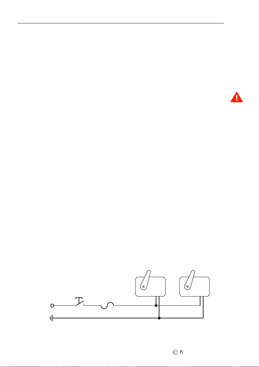
3.1 Electrical Power
The autopilot servo motor must be connected to a 12 V DC standard aircraft
power source. It is also possible to use 24 V DC power. The maximum current
consumption for one servo motor is 1.5 A (at 12 V). Always protect servos
with an automatic/replaceable fuse and a switch. The fuse protects against
over-current and the switch allows quick disconnect by taking power from the
motor. Figure 3 shows typical connection.
Fuse 5A
Autopilot
switch
+12V
Ground
Figure 3: Typical connection of servo motor electrical power.
14
©
Kanardia 2016-2020

Autopilot Installation Manual 3.2 CAN Bus
The autopilot switch must be easily accessible by the pilot. The pilot must
be able to reach it in any moment.
3.2 CAN Bus
Servo motor must also be connected to the CAN bus. The controller module
is built in the servo housing. The controller exchanges the information over
the CAN bus. In addition, CAN bus is also used to power the controller. This
means that controller works even when servo motors are without power.
Figure 4 shows CAN bus connections for the minimal autopilot configuration.
In reality more devices can be connected to the CAN bus. The CAN bus goes
trough Nesis or Aetos, where it is internally connected to AD-AHRS-GPS
module. On the servo side, T junction is needed and a short connection is
made from T to the servo controller.
Airu
AD-AHRS-GPS
T T
CAN bus
to other devices to other devices
Nesis III or Aetos
CtrlCtrl
Figure 4: Typical CAN bus connection for Nesis/Aetos based minimal autopi-
lot configuration.
Please note that CAN bus must be terminated with a 120 Ohm terminator
on both ends of the main line. Terminators are not shown on Figure 4.
3.3 External Push Button
It is advisable to install an external push button, which allows for quick
autopilot disconnect and level commands. The push button shall be installed
on the command stick, where it is easily accessed by pilot. Two wires from
15
©
Kanardia 2016-2020

Autopilot Installation Manual 3.4 Joyu Command Stick
the push button must be connected to the Nesis/Aetos service port or to
Amigo auxiliary port. The connection details are given in the Nesis/Aetos
installation or in Amigo manual, see the External Push Button section.
3.3.1 Autopilot Quick Disconnect
Nesis/Aetos must be then configured to react on the push button event. When
the button is pushed, the autopilot disconnect command is sent via CAN bus
to both servo controllers, which will cut power of both servo motors.
In the case of Amigo, no configuration is necessary.
3.3.2 Autopilot Level
The same button can be used also used for the autopilot level command. This
command will activate Track Hold mode for aileron and Altitude Hold mode
for elevator.
In the case of Nesis/Aetos, this function must be configured. In the case of
Amigo, it is activated by a long press on the external button. No configuration
is necessary.
3.4 Joyu Command Stick
Alternatively, Joyu command stick can be also used. Joyu has multiple pro-
grammable buttons and one or more of its buttons can be assigned to operate
the autopilot.
Short press on the button should be used for autopilot disconnect and long
press for the autopilot level function.
Please see the Joyu manual for more details.
4 Configuration
For the autopilot to operate properly, controllers inside the servo motors must
be configured. Once the configuration is complete, the whole system must be
also tuned. In general, tuning is needed for every airplane. In most cases air-
planes of the same type may use the same autopilot configuration if autopilot
mechanical installation is identical.
Any accidental change of any of parameters in this section and subsections
may result of autopilot being inoperative.
16
©
Kanardia 2016-2020

Autopilot Installation Manual 4.1 Overview
4.1 Overview
These configuration and tuning can be done either with Nesis/Aetos or with
Amigo. This section includes several figures. Each figure illustrates Ne-
sis/Aetos solution on the left and Amigo solution in the right.
If you have both Nesis/Aetos and Amigo, do not use the Autopilot configura-
tion or tuning on both instruments at the same time. Use either Nesis/Aetos
or Amigo.
Next steps reveal typical workflow:
1. Configure both servos. Each servo has several parameters that must
be set properly. Its function (what it moves – ailerons or elevator) and
movement direction are two examples.
2. Ground test is performed. It tells weather servos are moving commands
(elevator and ailerons) in correct directions.
3. Autopilot operation limits are set. They define an envelope of values,
which must be met for AP to operate. This is a very important safety
feature.
4. Autopilot controller parameters are set. Most of them can be set on the
ground, but some must be adjusted during flight tests.
5. Autopilot is tuned, which is the most difficult part. This can be per-
formed only in flight. Several controller values must be determined.
First three steps shall be set on the ground. Most of the fourth step can be
also set on the ground, but may be necessary to change some of parameters
during the flight test. Final step can be only done in flight.
Section 7 reveals the workflow for airplanes where autopilot parameters are
already known.
4.2 Autopilot Settings
Please refer also to the Nesis/Aetos or Amigo manual.
In Nesis/Aetos, the settings are accessible from Service options page in the
display. Special password (provided with the instrument) must be entered to
access the Service options page. The password can be also found under the
Info icon.
17
©
Kanardia 2016-2020

Autopilot Installation Manual 4.2 Autopilot Settings
In Amigo, press and hold the ALT knob and then select the Autopilot from
the menu.
Figure 5 shows the main autopilot settings menu. Nesis/Aetos version is on
the left and the Amigo version is on the right. This pattern repeats throughout
this section.
Figure 5: Main autopilot settings menu.
The menu items follow the logic from the workflow:
Servo config is used to configure servo motors. Section 4.2.1 reveals the
details.
Ground test is used to make sure that servos are correctly moving the con-
trols. See section 4.2.2.
Limits is used to define valid operation envelope of the autopilot, section
4.2.3.
Parameters is used to define various controller parameters, section 4.2.4.
Tuning is an in-flight operation used to setup PID terms of the controller
loops for the elevator and aileron. See section 5.5.
4.2.1 Servo Configuration
When setting up an autopilot, configuring the servos is the first step. Two
servos are required: one for elevator and the other for ailerons. A servo can
perform either role. Each servo has its own serial number.
During the mechanical installation, write down the serial number of the servo
which was connected to aileron and the serial number of the servo used for
elevator.
18
©
Kanardia 2016-2020

Autopilot Installation Manual 4.2 Autopilot Settings
Select the servo to configure. A selection example is shown on Figure 6.
Figure 6: An example of servo selection based on serial number.
Once serial number is selected a window with servo details opens, Figure 7.
Figure 7: An example of servo settings window.
The servo configuration window defines following parameters:
Function must match the servo mechanical connection. If servo with given
serial number is connected to the aileron, then the function must also
be Aileron. Change the function if necessary. You can choose between
Aileron or Elevator.
Reversed has values No or Yes. Choosing correct value is a guessing game.
Start with No and if ground test, described in section 4.2.2 fails, change
it to Yes and vice versa.
Power defines how much power (=torque) shall be used by servo when moving
its arm. 100% means total servo capacity. Try to avoid using more than
90% due to possible servo overheating. This also depends where and
19
©
Kanardia 2016-2020

Autopilot Installation Manual 4.2 Autopilot Settings
how servo is installed. In long term, try to find the lowest value, which
still provides enough torque.
Holding power defines how much power is used when motor is not moving.
This value depends on the power value above. If it is set to 50% this
means that motor will use 50% of the torque set with the power param-
eter. For example, if power is set to 70% and holding power is set to
50%, the motor will use 35% of maximal power (torque) at standstill.
Backlash defines the amount of command system free travel, which is a com-
bination of free play and elastic command resistance. It is given in
degrees of servo arm movement. In ideal circumstances this shall be
zero, but this is seldom the case.
Max speed is the maximal speed of servo arm movement in degrees per sec-
ond. This value is usually set between 10 and 30 deg/s.
PPR tells how many pulses are needed for one rotation of internal stepper
motor (always 200 for current servos). This is servo motor characteris-
tics and shall not be changed.
Reduction is the gearbox reduction factor between the arm and stepper mo-
tor. (This factor is 4.57 for recent servos. But factors between 4 and
5 are also in use.) This is servo motor characteristics and shall not be
changed.
In general, PPR,Reduction and Max speed shall not be changed and original
values shall be kept. Change them only if Kanardia support team approves
the changes.
4.2.2 Ground Test
The ground test is used to check correct servo motor movement. Figure 8
illustrates available options.
20
©
Kanardia 2016-2020
Table of contents


