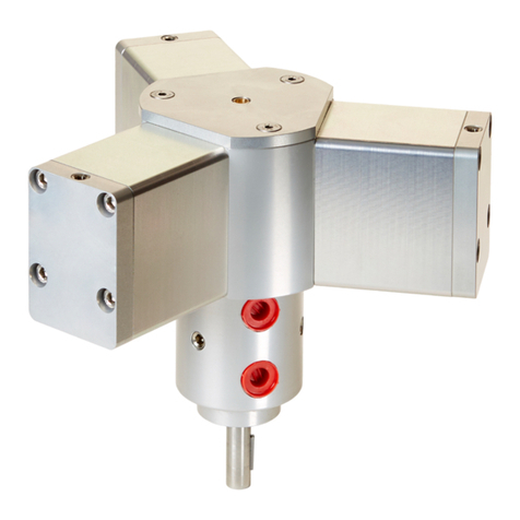
Autoquip Eco-2M User manual

www.aqautomation.com
Eco-2M Piston Air Engine™
Series III
Piston Air Engine™Installation
and Operating Instructions

www.aqautomation.com
WARNING
EQUIPMENT MISUSE HAZARD
Equipment misuse can cause the equipment to rupture or malfunction and result in
serious injury.
•This equipment is for professional use only.
•Read all instruction manuals, tags, and labels before operating the
equipment.
•Use the equipment only for its intended purpose. If you are not sure, call
your Autoquip distributor.
•Do not alter or modify this equipment. Use only genuine Autoquip parts.
•Check equipment daily. Repair or replace worn or damaged parts
immediately.
•Use fluids and solvents that are compatible with the equipment wetted parts.
Refer to the Technical Data section of all equipment manuals. Read the
fluid and solvent manufacturer’s warnings.
•Always wear protective eyewear, gloves, clothing, and respirator as
recommended by the fluid and solvent manufacturer.
•Comply with all applicable local, state, and national fire, electrical, and safety
regulations.
•Rotating parts may cause injury potential.

www.aqautomation.com
Piston Air Engine Installation and Operating Instructions
Operating Recommendations
1. Autoquip Piston Air Engines™are designed and built to be safe and reliable when
properly used. Advice and approval should be sought from authorized Autoquip
Automation personnel before any of our products are used in circumstances other than
recommended herein.
2. Compressed air is the only medium to be used.
3. Air pressure should not exceed 6.9 bar (100 psi)
4. Each engine should be supplied with air that is adequately filtered to remove fluids
and particles above 40 microns.
5. An operating temperature range of -10˚C to +80˚C (14˚F to 176˚F) is
recommended.
6. Engines should be sited and mounted to avoid excessive vibration.
7. Safety or system integrity should not depend upon the assumption that leakages
cannot or will not occur.
8. Actual response times for air engines can vary according to ambient conditions and
service life.
9. Adequate regular maintenance is essential to ensure continuous satisfactory and safe
performance.
Installation
1. Autoquip Piston Air Engines™are precision machines and are susceptible to damage
by dirt particles. Cleanliness is essential during installation and servicing.
2. To prevent ingress of dirt or grit do not remove the red protective caps (10) from the
ports until installed.
3. When the engine has been mounted and the shaft connected, air supply tubes should
be fitted to the ports ensuring that no dirt or grit can enter the ports

www.aqautomation.com
Start-Up
1. Set air pressure to zero.
2. Set any speed restrictor valves to the fully open position
3. Slowly increase air pressure until the shaft rotates under load.
4. For low load applications, increase air pressure by a further 1 –1.25 bar (15 –20
psi). This may not be necessary for high load applications.
5. Adjust the speed restrictor to give the required speed.
6. The air engine will now be running at the optimum and most efficient setting.
Note: It is bad practice to apply excessive line air pressure and then have a tight restriction on the
exhaust port. This can cause excessive wear on the base of the pistons.
Recommended Lubricants
Shell Gadus S2 V100 3
Maintenance Procedures
Autoquip Piston Air Engines™are precision engineered and are designed for a long
working life. The wearing parts are the pistons, cylinder liners and seals, which can be
replaced as part of a routine maintenance schedule.
For this purpose, spare parts kits can be purchased from Autoquip Automation or our
authorized distributors, comprising three pistons, three liners, three piston seals and
three O Rings.
The drive shaft and rotary valve assembly are matched during manufacture and should
not be removed from the engine body. If they are removed, they will require
replacement with new parts in our factory.
As with all precision engineered machines, cleanliness is essential during dismantling
and assembly. Before dismantling, the air supply ports must be covered with plastic
caps and the workbench should be clean and free of debris.

www.aqautomation.com
Disassembly
1. Ensure that all air lines are disconnected from the engine
2. Remove the three countersunk screws holding the rear cover to expose the
crank area.
Remove the three-cylinders by withdrawing the two bolts on each cap.

www.aqautomation.com
3. The three exposed ports of the air flow route (2 on each cylinder cap and
3 on the body) must be protected to prevent any ingress of dirt/grit. This
is critical.
4. Push out the three piston/liner assemblies; push outwards from the
crankcase with the seals and the O Rings.

www.aqautomation.com
5. Clean the crank area and cylinder bores using a suitable solvent to ensure
it is free from dirt particles.
Shaft and bushings are assembled as a unit and should not be
removed.
If you find the shaft will not rotate freely, we recommend you
contact Autoquip prior to any further work.

www.aqautomation.com
4. The three exposed ports of the air flow route (1 on each cylinder)
must be protected to prevent any ingress of dirt/grit. This is critical.
Reassembly
1. Ensure all parts are clean and grit free
2. Insert replacement piston/liner/seal assemblies ensuring that the seal
is at the cylinder cap end.
3. Fit the O Ring in the groove on cylinder depending on the type.

www.aqautomation.com
5. Apply a small amount of grease to the crank bearing. Piston kits are
supplied greased. Do not fill the crankcase with grease, as this impairs
operation. New engines are supplied greased with approximately 16
grams (0.5 oz.)
6. Re-connect the air supply, making sure the pressure is at zero.
7. Slowly increase the air pressure to approx 1 –1.25 bar (15-20 psi) the
engine should start to rotate slowly.
8. Disconnect air supply and replace rear cover.

www.aqautomation.com
Eco-2M Piston Air Engines™
Size 2 Engine 3077-HAE2-000
Service Options
Size 2 Engine Body Sub-Assembly Kit 3077-BSA2-000
Size 2 Rebuild Kit 3077-RKT2-000
Recommended Installation Kit
Size 2 Installation Kit = 3077-INST-000

www.aqautomation.com

www.aqautomation.com
3077-HAE2-000
Item
Description
1
Body
Body Sub-Assembly. Modification by customer not
recommended. Replacement Body Sub-Assembly
3077-BSA2-000
Items included:
1-13 and 23
2
Drive Shaft
3
Ball bearing
4
Ball bearing
5
Oilite bush
6
Air Seal
7
Washer
8
Screw hex head
9
Pin
10
Dust Cap
11
Plug
12
Seal Plate
13
Screw csk head
16
Cover
Items 16, 17 & 18 not available for individual purchase
17
Vent air silencer
18
Screw csk head
19
Piston Liner
Piston Sub-Assembly, Rebuild Kit 3077-RKT2-000
[3 Pistons]
Item included:
19-23
20
Piston
21
Piston Seal
22
O ring seal
23
O ring seal
24
Cylinder
Items 24 & 25 not available for individual purchase
25
Screw cap head
#3077 - Rev C
This manual suits for next models
1
Table of contents
Other Autoquip Engine manuals
