manuals.online logo
Brands
  1. Home
  2. •
  3. Brands
  4. •
  5. AUTOTECH
  6. •
  7. Automobile Accessories
  8. •
  9. AUTOTECH 10.109.01.109 User manual

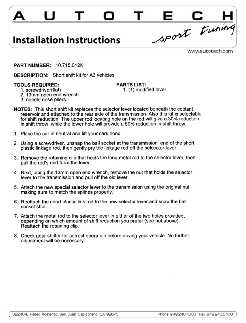
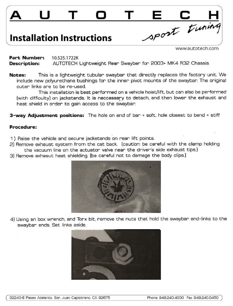
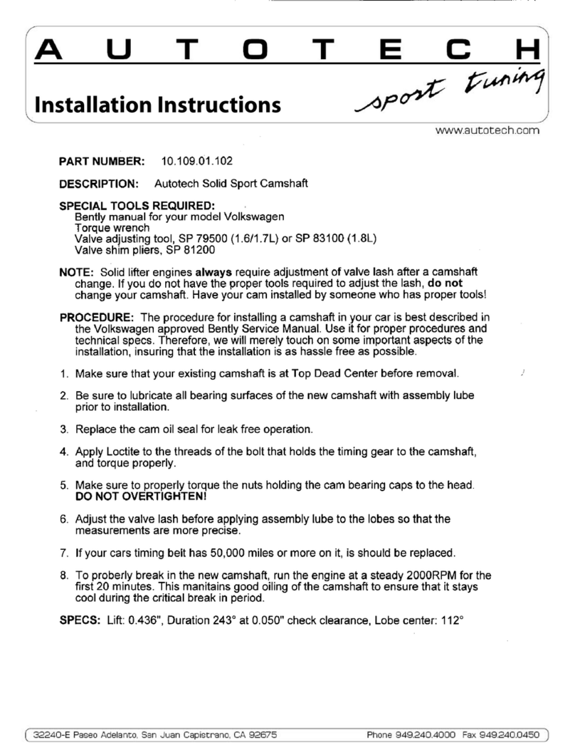
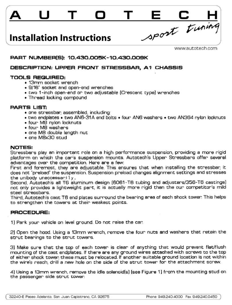
AUTOTECH 10.109.01.109 User manual

AUTOTECH
Part Number: 10.109.01.109
Description: AUTOTECH Sport 270° Hydraulic Camshaft
Note: If the job seems to be beyond your abilities, we recommend that you refer this in-
stallation to a qualified mechanic. Please read through the instructions before starting
your installation to ensure that you have have the tools and understanding of the task.
Procedure for Golf 2 and Jetta 2 models only:
1. Remove the valve cover by removing the eight 10mm valve cover nuts and reinforcing
strips. Remove idle stabilizer and bracket (if your car has one) by removing the 10mm bolts
from the valve cover and manifold, and then taking off the hoses at the throttle body and
intake manifold. Lift off valve cover. Remove the retaining nut on the side of the camshaft
drive belt cover with a 6mm allen wrench and lift off the cover.
2. Move camshaft sprocket to cylinder number one TDC mark by turning crankshaft clock-
wise with a 19mm socket until the dot on the camshaft pulley lines up with the upper edge
of the camshaft drive belt inner cover (fig. 1). Check TDC by removing the distributor cap
and making sure the rotor lines up with the notch on the distributor (fig. 2), and that the
flywheel is at TDC (fig. 3). If these marks do not line up, you will need to continue to rotate
the crankshaft until they do.
3. Loosen belt tensioner with a 15mm open end wrench and slide off the camshaft drive
belt, while keeping the belt tension on the lower sprockets so that they don't move or slip.
If they do, you will probably have to re-align them in a procedure described later. By tying
the belt via a bungee or other cord to the hood or laying the belt towards the rear using a
weight (wrench etc...) to keep the belt tension, you can install the cam without having to re-
align all of the sprockets.
4. Remove bearing caps one and three, in that order. Take note of which end of each cap is
pointing towards you. Caution: The bearing caps are offset, and will break if re-installed
backwards and tightened down. Next, remove the nuts from bearing caps two and five a
little at a time and crosswise so that the spring tension is evenly relieved. Lift cam with
attached sprocket out of the head.
5. Loosen the camshaft sprocket bolt 1/2 to 3/4 turn and tap the sprocket loose using a
soft faced hammer. Remove the bolt completely and remove the sprocket, woodruff key, and
cam seal. Lightly coat the cam seal with oil and place on the new camshaft. Install the
woodruff key and sprocket onto the new camshaft and torque the cam sprocket mounting
bolt to 59 ft/lb.
Installation Instructions
Phone 949.240.4000 Fax 949.240.045032240-E Paseo Adelanto, San Juan Capistrano, CA 92675
6. Apply oil to the bearing surfaces, and a small amount of assembly lube to the lobes of
the new camshaft. Lay the camshaft in the head with the lobes for the number one cylin-
der facing up. Install bearing caps two and five, tightening down gradually and crosswise
until the camshaft is pushed completely into the bearing saddles. Install the remaining
bearing caps and torque all nuts to 15 ft/lb.
7. Check to see if the dot on the inside of the cam sprocket lines up with the upper edge
of the camshaft drive belt inner cover (fig. 1). If not, rotate cam slightly until it does.
8. Re-install the valve cover and reinforcing strips, tightening the nuts to 7 ft/lb.
9. Slide camshaft drive belt over cam sprocket.
10 . Using a special spanner wrench (AST P/N 10.012.86400 or equiv.), tighten the drive
belt by rotating the tension pulley in the direction of the arrow (fig. 4). The belt should feel
tight when twisted 90 degrees with the thumb and forefinger, halfway between the cam-
shaft and intermediate shaft pulleys. Tighten the pulley retaining nut to 33 ft/lb.
11. Caution! Before starting engine, turn crankshaft two complete revolutions and check
belt tension, camshaft alignment, crankshaft alignment, and distributor alignment. If every-
thing checks out, re-install distributor cap, timing belt cover, and idle stabilizer valve if so
equipped.
12 . Start engine and run it at around 2000 RPM for twenty minutes. This is the crucial
break-in period for a new cam. It is important that the cam has good oil pressure at this
time! Once twenty minutes are up, you're ready to run.
Fig. 1 Fig. 2 Fig. 3
Fig. 4
AUTOTECH
Installation Instructions
Phone 949.240.4000 Fax 949.240.045032240-E Paseo Adelanto, San Juan Capistrano, CA 92675
Camshaft Drive Belt Alignment Procedure, Golf 2, Jetta 2, Fox
1. Loosen, but do not remove the lug nuts on the of passenger side road wheel. Jack up the pas-
senger side of the car and support it with a jackstand. Remove road wheel. Remove plastic inner
wheel housing liner/splash shield with a 8mm socket.
2. Loosen the water pump pulley bolts. Loosen the A/C and alternator mounting bolts. Loosen
adjusting screws to provide the slack required to remove the belts. The tensioning mechanism for
the A/C compressor is in the form of a bolt that is part of the mounting bracket itself. Remove
belts and the water pump pulley. Loosen tension pulley and slide off the camshaft drive belt
3. Remove the lower drive belt cover by removing the two nuts and bolt that hold it to the water
pump and front of the motor. Remove all four spark plugs to allow the crankshaft to turn easier
when you adjust it. Set motor to TDC (see step 2 of instructions).
4. Your crankshaft vs. intermediate shaft timing should already be close if you put the motor at
TDC before beginning your cam install. Rotate crankshaft (by hand using a wrench or socket on the
end of the crank) and intermediate shaft until the dot from the intermediate shaft is visible
through the "V" in the crankshaft pulley (fig.1). Caution: Rotate the crankshaft the least amount
necessary align the marks. Since the drive belt is not installed, there may be piston to valve inter-
ference if you try to rotate the crankshaft too much.
5. Check camshaft timing mark, make sure that the dot on the inside of the cam sprocket is lined
up with the camshaft drive belt inner cover (fig 1).
6. Install the camshaft drive belt by sliding it over the sprockets. Start at the crankshaft, then
the intermediate shaft, and finally the camshaft. Try to keep the belt as tight as possible between
the crankshaft and the intermediate shaft, and between the intermediate shaft and the camshaft
sprockets.
7. Using a special spanner wrench (AST P/N 10.012.86400 or equiv.), tighten the drive belt by ro-
tating the tension pulley in the direction of the arrow (fig. 2). The belt should feel tight when
twisted 90 degrees with the thumb and forefinger, halfway between the camshaft and intermediate
shaft pulleys. Tighten the pulley retaining nut to 33 ft/lb.
fig 1 fig 2
AUTOTECH
Part Number: 10.109.01.109
Description: AUTOTECH Sport 270° Hydraulic Camshaft
Note: If the job seems to be beyond your abilities, we recommend that you refer this instal-
lation to a qualified mechanic. Please read through the instructions before starting your
installation to ensure that you have have the tools and understanding of the task.
Procedure for Golf 3 and Jetta 3 models only:
1. Remove upper drive belt cover by unsnapping the bands fastening it to the head.
2. Move camshaft sprocket to cylinder number one TDC mark by turning crankshaft clock-
wise with a 19mm socket until the dot on the camshaft pulley lines up with the arrow on
the drive belt cover (fig. 1). Check TDC by removing the distributor cap and making sure
the rotor lines up with the notch on the distributor (fig. 2), and that the flywheel is at TDC
(fig. 3). If these marks do not line up, you will need to continue to rotate the crankshaft
until they do.
3. Remove upper intake manifold. Remove all connected vacuum hoses, electrical connections
(i.e. throttle body, etc...), and throttle cable from the upper manifold. Remove the five socket
head bolts (located near the fuel rail) and remove the manifold. Note: It is a good idea to
either tape over, or place clean rags in the lower intake manifold to prevent foreign objects
from falling in.
4. Loosen belt tensioner with a 15mm open end wrench and slide off the camshaft drive
belt, while keeping the belt tension on the lower sprockets so that they don't move or slip. If
they do, you will probably have to re-align them in a procedure described later. By tying the
belt via a bungee or other cord to the hood or laying the belt towards the rear using a
weight (wrench etc...) to keep the belt tension, you can install the cam without having to re-
align all of the sprockets.
5. Remove valve cover by removing the eight 10mm nuts and reinforcing strips.
6. Remove bearing caps one, three and five, noting which end of each cap is pointing to-
wards you. Caution: The bearing caps are offset, and will break if re-installed backwards
and tightened down. Next, remove the nuts from bearing caps two and four a little at a
time and crosswise so that the spring tension is evenly relieved. Lift cam with attached
sprocket out of the head.
7. Loosen the camshaft sprocket bolt 1/2 to 3/4 turn and tap the sprocket loose using a
soft faced hammer. Remove the bolt completely and remove the sprocket, woodruff key, and
cam seal. Lightly coat the cam seal with oil and place on the new camshaft. Install the
woodruff key and sprocket onto the new camshaft and torque the cam sprocket mounting
bolt to 59 ft/lb.
Installation Instructions
Phone 949.240.4000 Fax 949.240.045032240-E Paseo Adelanto, San Juan Capistrano, CA 92675
8. Apply oil to the bearing surfaces, and a small amount of assembly lube to the lobes of
the new camshaft. Lay the camshaft in the head with the lobes for the number one cylin-
der facing up. Install bearing caps two and four and tighten down gradually and crosswise
until the camshaft is pushed completely into the bearing saddles. Install the remaining
bearing caps and torque all nuts to 15 ft/lb.
9. Check to see if the arrow on the drive belt cover is pointing directly to the dot between
the "O" and the "T" on the camshaft sprocket (Fig 1). If not, rotate cam slightly until it does.
10 . Re-install the valve cover and reinforcing strips, tightening the nuts to 7 ft/lb.
11. Slide camshaft drive belt over cam sprocket.
12 . Using a special spanner wrench (AST P/N 10.012.86400 or equiv.), tighten the drive
belt by rotating the tension pulley in the direction of the arrow (fig. 4). The belt should feel
tight when twisted 90 degrees with the thumb and forefinger, halfway between the cam-
shaft and intermediate shaft pulleys. Tighten the pulley retaining nut to 33 ft/lb.
13. Caution! Turn crankshaft two complete revolutions and check belt tension, camshaft
alignment, crankshaft alignment, and distributor alignment. If everything checks out, re-
install distributor cap and timing belt cover.
14 . Re-install the upper intake manifold and tighten the five manifold bolts to 15 ft/lb. Re-
install all the vacuum and electrical connections that were disconnected earlier.
15 . Start engine and run it at around 2000 RPM for twenty minutes. This is the crucial
break-in period for a new cam. It is important that the cam has good oil pressure at this
time! Once twenty minutes are up, you're ready to run.
fig. 1 fig. 2
fig. 3 fig. 4
AUTOTECH
Installation Instructions
Alignment procedure for 4 cylinder Golf 3, Jetta 3, and Passat models
Caution: Use the least amount of rotation necessary to align the crank/camshaft to their
respective markings. Since the drive belt is not installed, there may be piston to valve inter-
ference if you try to rotate them too much. If you have to rotate the camshaft a great
deal, make sure that there are no pistons at TDC before doing so.
1. Set motor to TDC (see step 2 on instruction sheet).
2. Loosen tension pulley and slide off camshaft drive belt.
3. Align dot between the "O" and the "T" of the camshaft sprocket with the arrow on the
drive belt cover (fig. 1).
4. Rotate crankshaft by hand until the TDC mark on the flywheel lines up with the pointer
in the bellhousing (fig 2).
5. Turn the intermediate shaft sprocket using the camshaft drive belt in direction of the
arrow (fig 3) until the distributor rotor lines up with the cylinder 1 marking on the distribu-
tor (fig 4).
6. Slide camshaft drive belt over tension pulley and camshaft sprocket.
7. Using a special spanner wrench (AST P/N 10.012.86400 or equiv.), tighten the drive belt
by rotating the tension pulley in the direction of the arrow (fig. 5). The belt should feel tight
when twisted 90 degrees with the thumb and forefinger, halfway between the camshaft and
intermediate shaft pulleys. Tighten the pulley retaining nut to 33 ft/lb.
fig. 2 fig. 3
fig. 5
fig. 4
fig. 1

Other AUTOTECH Automobile Accessories manuals

AUTOTECH 10.715.010K User manual

AUTOTECH

AUTOTECH 10.715.010K User manual

AUTOTECH 10.941.060K User manual

AUTOTECH

AUTOTECH 10.941.060K User manual

AUTOTECH 10.998.230K User manual

AUTOTECH

AUTOTECH 10.998.230K User manual

AUTOTECH 10.109.418K User manual

AUTOTECH

AUTOTECH 10.109.418K User manual

AUTOTECH 10.435.001K-002K User manual

AUTOTECH

AUTOTECH 10.435.001K-002K User manual

AUTOTECH 10.430.217K-218K User manual

AUTOTECH

AUTOTECH 10.430.217K-218K User manual

AUTOTECH 10.715.011K User manual

AUTOTECH

AUTOTECH 10.715.011K User manual

AUTOTECH 10.425.1725GK User manual

AUTOTECH

AUTOTECH 10.425.1725GK User manual

AUTOTECH 10.129.020K-021 User manual

AUTOTECH

AUTOTECH 10.129.020K-021 User manual

AUTOTECH 10.425.1425GK User manual

AUTOTECH

AUTOTECH 10.425.1425GK User manual

AUTOTECH 10.715.098K-099K User manual

AUTOTECH

AUTOTECH 10.715.098K-099K User manual

AUTOTECH 10.698.400K User manual

AUTOTECH

AUTOTECH 10.698.400K User manual

AUTOTECH 10.199.023K User manual

AUTOTECH

AUTOTECH 10.199.023K User manual

AUTOTECH 10.109.402K User manual

AUTOTECH

AUTOTECH 10.109.402K User manual

AUTOTECH 10.251.132K User manual

AUTOTECH

AUTOTECH 10.251.132K User manual

AUTOTECH 10.698.005K User manual

AUTOTECH

AUTOTECH 10.698.005K User manual

AUTOTECH 10.525.1128K User manual

AUTOTECH

AUTOTECH 10.525.1128K User manual

AUTOTECH 10.715.012K User manual

AUTOTECH

AUTOTECH 10.715.012K User manual

AUTOTECH 10.525.1722K User manual

AUTOTECH

AUTOTECH 10.525.1722K User manual

AUTOTECH 10.109.01.102 User manual

AUTOTECH

AUTOTECH 10.109.01.102 User manual

AUTOTECH 10.430.005K-009K User manual

AUTOTECH

AUTOTECH 10.430.005K-009K User manual

AUTOTECH 10.611.208K-212K User manual

AUTOTECH

AUTOTECH 10.611.208K-212K User manual

AUTOTECH 10.530.001K-002K User manual

AUTOTECH

AUTOTECH 10.530.001K-002K User manual

AUTOTECH 10.525.1529K User manual

AUTOTECH

AUTOTECH 10.525.1529K User manual

Popular Automobile Accessories manuals by other brands

PNEUMATIC KU-RE-LO00-02 Installation instruction

PNEUMATIC

PNEUMATIC KU-RE-LO00-02 Installation instruction

Holland 17 Series Rebuild/Repair Manual

Holland

Holland 17 Series Rebuild/Repair Manual

EOinnovations EOC3103 instruction manual

EOinnovations

EOinnovations EOC3103 instruction manual

AL-KO AKS 3004 Service information

AL-KO

AL-KO AKS 3004 Service information

Warn 70045 installation instructions

Warn

Warn 70045 installation instructions

Pyle PLCM34WIR user manual

Pyle

Pyle PLCM34WIR user manual

SportRack A30404TW200 manual

SportRack

SportRack A30404TW200 manual

Excalibur RF-50-EDP Operation guide

Excalibur

Excalibur RF-50-EDP Operation guide

Circutor Raption 150 Series installation guide

Circutor

Circutor Raption 150 Series installation guide

Safe Fleet Prime Design FBM-1029 quick start guide

Safe Fleet

Safe Fleet Prime Design FBM-1029 quick start guide

Bestop HighRock 4x4 42950 installation instructions

Bestop

Bestop HighRock 4x4 42950 installation instructions

Rati Armster OE1 user manual

Rati

Rati Armster OE1 user manual

Adaptiv Mini CAM-AU9-AD FITTING & USER GUIDE

Adaptiv Mini

Adaptiv Mini CAM-AU9-AD FITTING & USER GUIDE

BOSSTOW S0927 quick guide

BOSSTOW

BOSSTOW S0927 quick guide

Fisher Minute Mount 2 system installation instructions

Fisher

Fisher Minute Mount 2 system installation instructions

ACME CH106 manual

ACME

ACME CH106 manual

BMW X5 Wide screen monitor 16:9 retrofit kit installation instructions

BMW

BMW X5 Wide screen monitor 16:9 retrofit kit installation instructions

Technaxx TX-170 user manual

Technaxx

Technaxx TX-170 user manual

manuals.online logo
manuals.online logoBrands
  • About & Mission
  • Contact us
  • Privacy Policy
  • Terms and Conditions

Copyright 2025 Manuals.Online. All Rights Reserved.