Autrol APT3200 Series User manual
*Information in this manual can be changed without advance notice.
Operation Manual: 111508-3200-OM01AUTROL Series
Operation Manual:201403-3200-OM00 V7x AUTROL®3200 Series
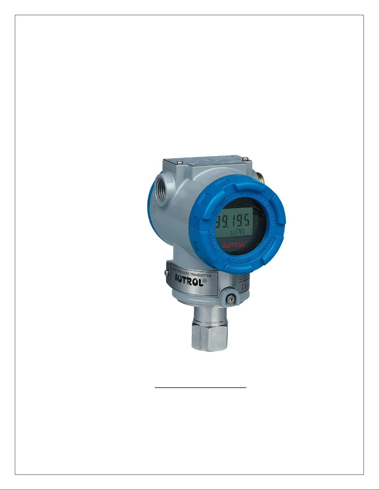
APT3200 Smart Pressure Transmitter
Operation Manual
AUTROL® APT3200 Series Operation Manual: 201403-3200-OM00 V7x
AUTROL CORPORATION OF AMERICA
www.autroltransmitters.com
published in USA

Operation Manual: 111508-3200-OM01AUTROL Series
Operation Manual:201403-3200-OM00 V7x AUTROL®3200 Series
APT3200 Smart Pressure Transmitter
This manual is made available to assist general users with instructions for proper installation and
operation of an Autrol® APT3200 Smart Pressure Transmitter.
Before handling the APT3200 transmitter, all users should read this manual to familiarize with
recommended practices.
Please note that information in this manual can be changed
without any advance notice. Please contact Autrol America Inc or our local representatives for any updates.
AUTROL CORPORATION OF AMERICA (AAI)
Corporate: Woodfield Preserve, 10 N. Martingale Rd, Suite 400, Schaumburg, IL60173
Operations: 2521 Technology Dr, Suite 200, Elgin, IL 60124
Tel.: +1 847-857-6062, 847 779 5000 Fax: +1 847-655-6062
www.autroltransmitters.com

i
Operation Manual: 111508-3200-OM01AUTROL Series
Operation Manual:201403-3200-OM00 V7x AUTROL®3200 Series
Table of Contents
Chapter 1.Introduction
1.1. Using this manual
1.2. Overview of the transmitter
1.3. Firmware compatibility
1.4. Transmitter Components
Chapter 2.Handling
2.1. Unpacking and specifications check
2.2. Model Code and specifications check
2.3. Storage
2.4. Selecting a suitable location for installation
2.5. Performing Zero Trim after first installation
2.6. Process Connection
2.7. Waterproofing of cable conduits
2.8. Restrictions on use of Radio Transceivers
2.9. Insulation Resistance Test and Dielectric Strength Test
2.10.Installation of Explosion Proof Transmitters in Classified Areas
2.11.EMC Conformity Standards
Chapter 3.Transmitter Functions
3.1. Overview
3.2. Safety Messages
3.3. Warning
3.4. Fail Mode Alarm
3.5. EEProm-Write Enable and Disable Mode Jumper
3.6. Configuration of Alarm and Security Jumper Procedures
3.7. Configuration using Zero and Span Push Buttons
3.8. Commissioning on the bench with a HHT (Hand Held Terminal)
Chapter 4.Installation
4.1. Overview
4.2. Safety Messages
4.3. Warning
4.4. Commissioning on the bench with a Hand-Held Terminal
4.5. General Considerations
4.6. Electrical Considerations
4.7. Wiring
4.8. Mechanical Considerations
4.9. Environmental considerations

ii
Operation Manual:110210-3200-OM01v7x AUTROL® Series
Chapter 5.On-line Operation
5.1. Overview
5.2. Safety Messages
5.3. Configuration Data Review
5.4. Check Output
5.5. Basic Setup
5.6. Detail Setup
5.7. Tag Information Setup
5.8. Diagnostic Services
5.9. Calibration
5.10.Advanced Setup
Chapter 6.Maintenance
6.1. Overview
6.2. Safety Messages
6.3. Hardware Diagnostics
6.4. Hardware Maintenance
Appendix I
APT3200 Smart Pressure Transmitter
LCD Display Codes
Appendix II
APT3200 Smart Pressure Transmitter
Quick Push Button Menu guide (Menu Tree)
Appendix Ⅲ
HHC HART® Handheld Communicator User’s Guide
HART®is a registered Trademark of HART Foundation

3
Operation Manual: 111508-3200-OM01AUTROL Series
Operation Manual:201403-3200-OM00 V7x AUTROL®3200 Series
Chapter 1 Introduction
The APT3200 Smart Pressure Transmitter is accurately calibrated at the factory
before shipment. If attempting to recalibrate these transmitters in field please use a
calibration source at least five times more accurate than transmitter published
specifications. In case of re-ranging please cosndier using the benefits of doing this
using the integral push buttons first prior to attempting any PV source to avoid
adding any unnecessary bias to the factory calibration. In case of of need to adjust
the factory calibration we suggest using the pushbuttons and –1 TRIM menus to
make the necessary Trim adjustments. To ensure correct and efficient use of the
instrument, please read this manual thoroughly and fully understand how to operate
the instrument before installation.
The contents of this manual are subject to change without prior notice.
All rights reserved. No part of this manual may be reproduced in any form
without AUTROL® AMERICA’s written permission.
For questions, errors or missing information found in this manual, please
inform the nearest AUTROL® AMERICA sales office or email
support@autroltransmitters.com.
The specifications covered by this manual are limited to standard configured
items as specified within published ordering codes and do not cover custom-
made instruments designated with code “X” or “L” within the model code.
Please note that changes in the specifications, construction, or component
parts of the instrument may not immediatelty be reflected in this manual at the
time of change, provided that postponement of revisions will not cause difficulty
to the user from a functional or performance standpoint.
1.1.Using This Manual
The Chapters in this operating manual provide information on installing,
operating, and maintaining an AUTROL® Model APT3200 Smart Pressure
Transmitter. Chapters within this manual are organized as follows.
Chapter 1: Introduction
Chapter 2: Handling
Chapter 2 provides instructons on software functions, configuration
parameters, and on-line variables.
Chapter 3: Transmitter Functions
Chapter 3 contains instructions for configuring and commissioning an Autrol®
APT series Smart Pressure Transmitter.
Chapter 4: Installation
Chapter 4 contains mechanical, environmental, and electrical installation
instructions for Autrol® APT series Smart Pressure Transmitters.
Chapter 5: On-line Operation
Chapter 5 describes the configuration process and how to use basic and
advanced Autrol® APT series Smart Pressure Transmitter software functions
during configuration. Included in these sections are details on using:
①Sensor or Output Trim
②Changing range configuration, Output Type, Damping, measurement units,
etc.
APT3200

APT3200
4
Operation Manual:110210-3200-OM01v7x AUTROL® Series
③Change of general data such as Tag No.,Date,Message, etc.
Chapter 6: Maintenance
•Chapter 6 contains hardware diagnostics ,troubleshooting and maintenace
tasks.
Appendix I :
List of Error Codes available on LCD display
Appendix II:
Push Button Menu guide (Menu Tree): configuration of operating settings
using pushbuttons built into exterior of transmitter, allowing change of settings
whenever transmitter is powered.
Appendix III:
HHC HART® Handheld Communicator User’s Guide
1.2.Overview of Transmitter
The Autrol® APT 3200 Smart Pressure Transmitter is a microprocessor based
“smart” pressure transmitter. It uses a piezoelectric pickup optimized &
accurately characterized to compensate for ambient temperature effecs with a
patented temperature compensation algorithm that ensures for high precision
& long term stablilty in gauge and absolute pressure measurements over a
wide range of operating conditions. APT3200 is a two wire loop power
transmitter and has a standard 4/20mA output scaled for desired output
pressure range. In addition it also offers digital HART® (digital signal
superimposed over the analog output) communication that allows transmitting
additional digital parameters/diagnostic information for advanced control
systems like DCS, PLC, SCADA, RTU, AMS etc. All APT series transmiters
have an explosion proof rated housing (standard cast aluminum–copper free
epoxy coated, or optional SUS316) protected for outdoor NEMA 4X/IP 67 and
classified hazardous areas Class I, II, III / Division 1 or 2 use. When installaing
in hazardous areas user must follow relevant electrical codes and wiring
practices per prevailing electrical standards.
This transmitter can be configured for its included smart functions (re-ranging,
damping, engineering mode, square root-linear transfer functions etc. ) using
local push buttons or remotely via HART® commmunication through a HART®
MASTER Host (AMS,PDM, PKS etc) , a HHT (HART® Hand-Held Terminal
using DDL or DOF technology) or any HART® enabled PC Configurator
supporting DDL technology. This allows critical variables to be changed,
configured and tested locally or remotely by users. Note: for HART®
Communication a minimum 250 Ohm loop resistance is mandatory.
1.3.Software Compatbility
Autrol® Smart Pressure Transmitters are shipped from the factory with the
most up to date firmware. However, as product developments and new
features are released a firmware update becomes necessary to incorporate
these new changes. Transmitters with older firmware may restrict certain
functions when communicating with local pusgbuttons and/or an external
HHT(Model 275 /375 or 465 HART® Communicator).
•Supported.ⅹ: Not Supported∆: Supported but updated FDR5 DDL required
Operation Manual:110210-3200-OM01 V7x AUTROL®Series
5
APT
APT3200
APT3200
APT3200
APT3200
In this case contact AAI for a recommended firmware update or uselatest FDR
DDL (Device Description Library) to ensure compatibility of the transmitterwith
connected HHT, PDM etc.
Important Note: There may also be some differences in supported functions on
the local push button menu based on the installed firmware revision of the
transmitter. This manual is based on Firmware Revision 7.0 and higher. Actual
firmware revision installed on transmitters can be identified by
(a)Firmware version printed on neck plate (below LCD module) .
(b)On LCD display imemdiately during initial power up/Boot up sequence.
(c)Via HHT or HART® UMPC in Info menu.
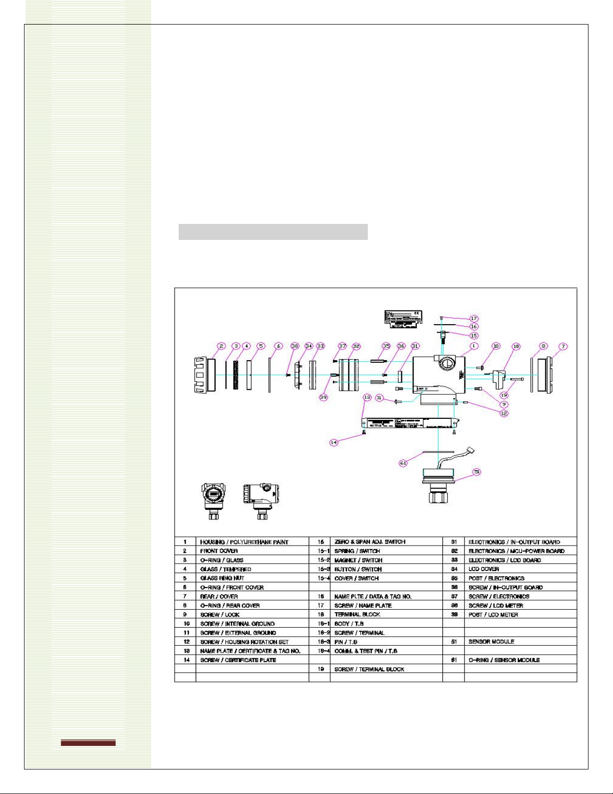
1.4.Transmitter Components
The various components of an Autrol® APT 3200 Series Smart Pressure
Transmitter are shown in Figure 1-1 below.
Figure 1-1. Model APT3200 Transmitter Exploded View

APT3200
6
Operation Manual:110210-3200-OM01v7x AUTROL® Series
Chapter 2 Handling
This chapter includes instructions for transmitter handling, storage, selection of
appropriate installation locations, insulation and cautions for hazardous area
installation.
[Quick Reference Table 2.0]
Step
Job
Job Details
Instrument
1
Unpacking
-Unpack transmitter from its packing
As applicable
2
Model and
Specifications
Check
-Make sure the delivered transmitter is same as
ordered and meets application requirements
Visual
Nameplate
3
Storage
-Please do not expose to rain, water, high humidity,
excessive vibration and high-impact areas
-Store under ambient temperature 70F and relative
humidity 65% RH
None
4
Bench
Calibration
- Configuration of Range, Zero/Span, Unit, Tag,
Damping Time, Transfer Function, DA Trim and other
parameters.
HHT/ Pressure
calibrator-(if
available)
- Ammeter for
output trimming.
5
Installation
Locations
-Where ambient temperature is not fluctuating.
-Where chemical corrosion is minimal.
-Where vibration and impact is not severe
-Where hazardous area is matched with explosion
proof classifications defined by local regulatory
bodies.
-Where maintenance access is easy
(Engineering)
6
Mechanical
Considerations
-Where transmitter can be handled easily
-Be cautious of pressure leaks.
(Engineering)
7
Electrical
Considerations
-Connect 24 Vdc (Recommended power supply is
11.9 Vdc –45 Vdc)
-For HART® communication, total resistance on
transmitter terminal loop should be 250 –550
Ohm.
(Engineering)
8
Mounting and
Installation
-For mounting transmitter, an appropriate bracket
(BA or BF type) should be used.
-Transmitter should be fixed firmly to its bracket.
(Mounting and
Installation)
9
Calibration
upon
installation.
-Sensor Zero Trim is highly recommended during
first installation and start-up. During a Zero trim the
zero baseline of transmitter is established.
-Before initiating zero trim make sure that PV value
of transmitter is zero and current output is at 4 mA.
Local Zero/Span
button or HHT
10
Pressure
-Do not apply differential and/or full line pressure
suddenly.
-Close equalizing valve of 3/5 valve manifold, then,
open stop valve on high and low side slowly and
simultaneously.
(Manual)
11
Operation
- Verify transmitter is operating within specifications.
Visual or HHT

Operation Manual:110210-3200-OM01 V7x AUTROL®Series
7
APT
APT3200
APT3200
APT3200
APT3200
2.1.Unpacking
When moving the transmitter to the installation site transfer it in its original
packaging. Only unpack the transmitter on site of installation to avoid damage
during transit.
2.2.Models and Specifications Check
The model name and specifications are indicated on the top nameplate fixed
to the transmitters. Please check your specification and model supplied for
your installation. Please ensure LRL (Lower Range Value) / URL (Upper
Range Value), min/max span specifications and MWP (Max. Working Pressure)
of sensor range codes are in line with your application requirements.
2.3.Storage
The following precautions must be observed when storing the instrument,
especially for long periods.
(1)Select a storage area that meets the following conditions:
a)It is not directly exposed to rain, water, snow or sun light.
b)It is exposed to minimum vibration and shock.
c)If possible, it is advisable to store at normal temperature and
humidity (approx. 70°F, 65% RH). However, it can also be
stored under ambient temperature and relative humidity within
the following published ranges.
Ambient Temperature:-40 ~ 85°C (without LCD) * or-
30 ~ 80°C (with module)*
* General use only. For explosion proof versions follow
product certification reqmts.
Relative Humidity: 5% ~ 98% RH (at 40°C)
(2)When storing the transmitter, repack with original (or similar)
packaging that was shipped from the factory.
(3)If storing a transmitter that has already been used, thoroughly clean
all wetted parts including diaphragm seals (if installed), process
connections/manifolds in contact with process fluid. In addition, make
sure before storing the transmitter that remote seal (if supplied)
assemblies are securely mounted.
2.4.Selecting a Suitable Location for Installation
The transmitter is designed to withstand severe environmental conditions.
However, to ensure stable and accurate operation for extended years, the
following precautions must be observed when selecting an installation location.
(1)Ambient Temperature:
Avoid locations subject to wide temperature variations or a significant
temperature gradient. If the location is exposed to radiant heat from
plant equipment, provide adequate insulation or ventilation.
(2)Ambient Atmosphere
Avoid installing the transmitter in a corrosive atmosphere. If the
transmitter must be installed in a corrosive atmosphere, there must be
adequate ventilation as well as preventive measures to minimize
intrusion or stagnation of rainwater or condensation build up through
its electrical conduits. Moreover, there should be appropriate
precautions taken to prevent corrosion build up due to condensation or
moisture collected within conduits and terminal boxes over extended

APT3200
8
Operation Manual:110210-3200-OM01v7x AUTROL® Series
periods of operation. Inspect periodically as required.
(3) Shock and Vibration:
Select an installation site subject to minimum shock and vibration.
Although the transmitter is designed to be relatively resistant to shock
and vibration, we highly recommend following good engineering
practices.
(4) Installation of Explosion Proof rated Transmitters
Explosionproof rated transmitters must be installed in hazardous areas
according to the area classification for which they are certified.
(5) Accessibility
Select location that provides easy access formaintenance & calibration.
(6) Selecting Power supply
Ensure proper supply voltages are calculated per maximum available
load and minimum required voltage requirements across supply input
of a two wire transmitter to avoid “loop loading” issues.
(7) Grounding
Select proper grounding techniques to avoid ground loops and
external noise influences.
2.5.Performing Sensor Zero Trim after Installation
(1) Sensor Zero Trim should be done immediately after transmitter is
installed because zero point can shift due to mounting status of the
sensor pick up. This can be done using local push buttons provided
on top of transmitter housing (underneath the SS nameplate)
(2) For Sensor Zero Trim, make input pressure of transmitter zero prior to
initiating zero trim calibration. Any Sensor Trim done in field must be
carried out after installation is finalized and with transmitter position
fixed. Also, if applying external pressure source (recommended for
absolute models only) ensure the display is sufficiently stabilized
(after approximately 10 to 15 seconds) before initiating any Trim
function.
(3) There are two recommendations for making input pressure “zero”.
One is to apply a “zero” pressure source (mandatory for absolute
pressure models). The second option is to open equalizing valve of
manifolds and venting to atmospheric pressure (allowed only for
Gauge type models).
(4) Sensor Zero Trim can be performed using an external HHC (Hand
held calibrator), PC or PDA configurator, and/or using Zero/Span local
push buttons provided on the transmitter.
(5) When using local push buttons please refer to Chapter 3.7 of this
manual for detailed instructions. If using an external HHT or HART®
PC configurator please refer to the user manuals supplied by the third
party supplier.
2.6.Pressure Connection
▲ Warning
◈Instrument installed in the process is under presure. Never loosen or tighten the
flange bolts as it may cause leakage of process fluid.
◈If the process fluid may be toxic or otherwise harmful, take approriate care to
avoid contactand/or exposure to direct vapors even after dismounting the
instrument from process line for maintenance.

Operation Manual:110210-3200-OM01 V7x AUTROL®Series
9
APT
APT3200
APT3200
APT3200
APT3200
Standard Process connection is ½” NPT. Optional ¼”NPT Process connection
is available with use of adapters (O option) if ordered with the transmitter.
The following precautions must be observed in order to safely operate the
transmitter under pressure.
(1)Never apply a pressure higher than the maximum working pressure
specified on the nameplate.
(2)Use adequate seals for leak tight process connections and use only
quality and standardized parts.
(3)Regularly inspect for signs of leakage and apply corrective actions
when necessary.
2.7.Waterproofing of Cable Conduit Connections
Apply a non-hardening sealant (viz. silicone or Teflon tape, etc.) to the threads
to water proof the cable conduit entry connections.
2.8.Restrictions on Use of Radio Transceivers
▲ Warning
◈Although the transmitter has been designed to resist high frequency electrical
noise, if a radio transceiver is used near the transmitter or its external wiring, the
transmitter may be affected by high frequency noise pickup. To test for such
effects, bring the transceiver in use slowly from a distance of several meters from
the transmitter, and observe the measurement loop for noise effects. Thereafter,
always use the transceiver outside the area affected by noise.
2.9.Insulation Resistance Test and Dielectric
Strangth Test
All APT series transmitters are subjected to insulation resistance and dielectric
strength tests (at the factory) prior to shipment. Normally these tests are not
required to be duplicated in field. However, if required, observe the following
precautions in the field test procedures.
(1)Do not perform such tests more frequently than is absolutely
necessary. Even test voltages that do not cause visible damage to the
insulation may degrade the insulation and reduce safety margins.
(2)Never apply a voltage exceeding 500 Vdc (100 Vdc with an internal
lightning protector--LP option) for insulation resistance test, or a
voltage exceeding 500V AC (100V AC with an internal lightning
protector option) for dielectric strength tests.
(3)Before conducting these tests, disconnect all power and signal lines
from the transmitter terminals. Follow procedures outlined below to
initiate these tests.
I. Insulation Resistance test
a)Short the (+) and (-) SUPPLY terminals inside the transmitter
terminal box.
b)Turn OFF the insulation tester. Then connect the insulation
tester positive (+) lead wire to the shorted SUPPLY terminals
on the transmitter and the negative (-) lead wire of tester to
the ground terminal on transmitter.

APT3200
10
Operation Manual:110210-3200-OM01v7x AUTROL® Series
c) Turn ON the insulation tester power and measure the
insulation resistance. The voltage should be applied for a
short duration sufficient enough only to verify that insulation
resistance measured is at least 20 MΩ.
d)After completing the test and being very careful not to touch
exposed conductors disconnect the insulation tester and
connect a 100kW resistor between the grounding terminal and
the short-circuiting SUPPLY terminals. Leave this resistor
connected for at least three seconds to discharge any static
potential. Do not touch the terminal while it is discharging.
II. Dielectric Strength Test
a)Short-circuit the (+) and (-) SUPPLY terminals marked in
the terminal box.
b)Turn OFF the dielectric strength tester. Then connect the
tester between the shorted SUPPLY terminal and the
ground terminal of transmitter.
c) Be sure to connect the grounding lead of the dielectric
strength tester to the ground terminal.
d)Set the current limit on the dielectric strength tester to
10mA, then turn ON the power and gradually increase the
tester voltage from '0' to the specified voltage. When the
specified voltage is reached, hold it for one minute.After
completing this test, slowly decrease the voltage to avoid
any voltage surges.
2.10.Installtion of Explosion Proof Transmitters in
Classified Areas
Installation
All wiring shall comply with local installation requirements.
Cable Glands shall be suitable for the environment and shall be
certified as explosion proof.
Unused conduit openings shall be properly sealed with certified
metallic plugs.
Grounding procedure must be followed in compliance with “local
electrical codes”. Recommended: use a qualified grounding earth
with least impedance.
Grounding options:
Internal Ground Connection: An Internal ground connection screw is
located inside the terminal housing accessible by opening the rear
cover. The ground screw can be easily identified from its ground
symbol marking.
External Ground Lug: This is located on the right side of housing and
accessible from outside. This ground screw can also be easily
identified from its ground symbol marking.
When using metallic conduits, stuffinging boxes/glands must be used.
All Cable Glands must be certified as explosion proof for area
classification.
Conduit thread must be engaged with a minimum of 5 thread
connections.
Process Connection should also be engaged with a minimum of 7
thread connections and housing rotation set screw (below front cover)
tightened to prevent housing from rotating.

Operation Manual:110210-3200-OM01 V7x AUTROL®Series
11
APT
APT3200
APT3200
APT3200
APT3200
Operation
Wait one minute after disconnecting power before opening the
enclosure.
Take care not to generate mechanical sparks when accessing the
instrument and peripheral devices in a hazardous location.
Maintenance and Repair
Instrument modification or parts replacement by other than authorized
factory representatives is prohibited and will void flameproof
certification.
2.10.1.KOSHA Certification
Caution for KOSHAFlameproof is following type.
[Note1]Model APT3200 sealed for potentially explosive atmosphere:
Type of Protection and Marking Code: Ex d ⅡC T6
Temperature Class: T6
Ambient Temperature: -20 ~ 60'C
Process Temperature: Max. 80'C
[Note2]Electrical Data
Supply Voltage: Maximum 45 Vdc
Output signal: 4 ~ 20mA, maximum 22mA
2.10.2.KEMA/ATEX Certification
ATEX Certification number : KEMA05ATEX2244
CE XXXX II 2 G
Note 1. Model APT3200 for potentially explosive atmosphere
Ex d IIC T6
Operating Température : -20℃≤
Note 2. Electrical Data
Supply Voltage : 45 Vdc Max
Output Signal : 4 to 20 mA + HART®
Note 3. Electrical Connection: 2 x 1/2-14NPT Female
Note 4. APT3200 ATEX Certification is according to the below
standards EN 60079-0
EN 60079-1
2.10.3.Factory Mutual (FM)USA Certification to NEC Codes
HAZARDOUS LOCATION ELECTRICAL EQUIPMENT
APT3200-abclgjkm. Pressure Transmitters.
APT3200-abcdefgijklm. Pressure Transmitters.
APT3200-abcdfghiklm. Pressure Transmitters.
XP/I/1/ABCD/T6 Ta = 60℃;
DIP/II, III/1/EFG/T6 Ta = 60℃;

APT3200
12
Operation Manual:110210-3200-OM01v7x AUTROL® Series
NI/I/2/ABCD/T4 Ta = 60℃;
S/II/2/EFG/T4 Ta = 60℃;
S/III/1/T4 Ta = 60℃;
Type 4X/IP67.
a = Transmitter Type D, G, H, LEC, LED, LES, LFC, LFD or LFS.
b = Ranges : 3, 4, 5, 6, 7, 8 or 9.
c = Mounting Flange Size & Material : C1, C2, C4, M11, M12, M13,
M14, M21, M22, M23, S2, S3 or S4
d = Mounting Flange Rating :A1, A2, D1, D2, J1, J2 or XX.
e = Extention Length : 05, 10, 15 or XX.
f = Wetted Parts Material : H, S or X.
g = Fill Fluid : 1, 2, 7 or X
h = Capillary Length : 01, 02, 03, 04, 05, 06, 07, 08, 09, 10, 11 or 12.
i = Material of Construction : CS or SS.
j = Low Side : N, W or X.
k = Electrical Connection : 1.
l = Hazardous Location Certification : F1.
m = Option : BA, BF, C6, CA, CF, K, M1, P, S or TW.
Equipment Rating :Explosionproof for use in Class I, Division 1, Groups
A, B, C &D; Dust-Ignitionproof for Class II, Division 1, Groups E, F and
G; Nonincendive for use in Class I, Division 2, Groups A, B, C and D;
Suitable for use in Class II, Division 2, Groups E, F and G; and Suitable
for Class III, Division 1; Hazardous(classified) location, indoor and
outdoor (NEMAType 4X/IP67).
2.10.4.FM Canada Certification confirming to CSA Standards
HAZARDOUS LOCATION ELECTRICAL EQUIPMENT
APT3200-abclgjkm. Pressure Transmitters.
APT3200-abcdefgijklm. Pressure Transmitters.
APT3200-abcdfghiklm. Pressure Transmitters.
XP/I/1/ABCD/T6 Ta = 60℃;
DIP/II, III/1/EFG/T6 Ta = 60℃;
NI/I/2/ABCD/T4 Ta = 60℃;
S/II/2/EFG/T4 Ta = 60℃;
S/III/1/T4 Ta = 60℃;
Type 4X/IP67.
a = Transmitter Type D, G, H, LEC, LED, LES, LFC, LFD or LFS.

Operation Manual:110210-3200-OM01 V7x AUTROL®Series
13
APT
APT3200
APT3200
APT3200
APT3200
b = Ranges : 3, 4, 5, 6, 7, 8 or 9.
c = Mounting Flange Size & Material : C1, C2, C4, M11, M12, M13,
M14, M21, M22, M23, S2, S3 or S4
d = Mounting Flange Rating :A1, A2, D1, D2, J1, J2 or XX.
e = Extention Length : 05, 10, 15 or XX.
f = Wetted Parts Material : H, S or X.
g = Fill Fluid : 1, 2, 7 or X
h = Capillary Length : 01, 02, 03, 04, 05, 06, 07, 08, 09, 10, 11 or 12.
i = Material of Construction : CS or SS.
j = Low Side : N, W or X.
k = Electrical Connection : 1.
l = Hazardous Location Certification : F1.
m = Option : BA, BF, C6, CA, CF, K, M1, P, S or TW.
Equipment Rating : Explosionproof for use in Class I, Division 1,
Groups A, B, C &D; Dust-Ignitionproof for Class II/III, Division 1,
Groups E, F and G; Nonincendive for use in Class I, Division 2, Groups
A, B, C and D; Suitable for use in Class II, Division 2, Groups E, F and
G; and Suitable for Class III, Division 1; Hazardous(classified) location,
indoor and outdoor (NEMAType 4X/IP67).
2.11.EMC Conformity Standards
EMI (Emission): EN55011
EMS (Immunity): EN50082-2
AAI recommends that customer follow installation requirements conforming to
EMC Regulations or to plant standards.

APT3200
14
Operation Manual:110210-3200-OM01v7x AUTROL® Series
Chapter 3 Transmitter Functions
2.
3.1.Overview
This chapter includes instructions to facilitate pre-installation set up
procedures for an AUTROL®APT series SMART Pressure transmitter. Tasks
that can be performed on the bench prior to installation in the field are also
explained in this chapter.
3.2.Safety Message
Procedures and instructions in this chapter may require special precautions to
ensure the safety of the personnel performing these operations. Information
that raises potential safety issues is indicated by warning symbol (▲). Refer to
the following safety messages before performing an operation preceded by
this symbol.
3.3.Warning
▲ Warning
Electrical shocks can result in death serious injury:
◈Avoid contact with the leads and terminals. High voltage that may be present on
leads can cause electrical shock.
◈Only qualfied & trained personnel should be allowed to operate these
transmitters
▲ Warning
Explosions can result in death or serious injury:
◈Do not remove the transmitter covers in hazardous locations when the circuit is
live.
◈Transmitter covers must be fully engaged to meet explosionproof approval
requirements.
3.4.Fail Mode Alarm
AUTROL® Smart Pressure Transmitter automatically performs real time self-
diagnostic routines and displays any error codes on its local LCD (Liquid
Crystal Display) (M1 option if ordered) that can be used for troubleshooting. In
addition to this, the self-diagnostic routines are also designed to drive
transmitter current output outside of the normal saturation values in case a
fault mode is detected. The transmitter will drive its current 4/20mA output low
(down) or high (up) based on the position of the failure mode alarm jumper(or
DIP switch) configuredin line with NAMUR requirements. See Table 3.1 for
available Current Output values.
[Table 3-1 StandardAlarm and Saturation Value]
Level
4~20mA Saturation
4~20mA Alarm
Low/Down
3.9 mA
≤ 3.75 mA
High/Up
20.8 mA
≥ 21.75 mA
Note: When connecting multiple transmitters in HART® multidrop mode the
current output is automatically parked at 4mA. In such installations Fail Mode

Operation Manual:110210-3200-OM01 V7x AUTROL®Series
15
APT
APT3200
APT3200
APT3200
APT3200
Alarm on Current output is automatically disabled; however, error indication is
still available via digital HART® communication as a Status Flag.
Fail Mode Selection (Fail High/UP or Low/DOWN) can be configured using the
appropriate jumper switch provided on the LCD Module or DIP switches
included on the Main CPU Module. For units provided with a LCD module one
can select desired fail safe mode directly from the jumper switch included in
the front display and this setting overrides the DIP settings on the back-end
Main CPU module. However, in the case of blind units please select your
required DIP switch settings from the DIP switch labeled (2) marked on the
Main CPU board. Recommended jumper & DIP settings are listed in Table 3-2
below for ready reference. To move jumper, pull out, then move to new
location and push in.
[Table 3-2 Jumper/DIP settings for Fail Mode Selections]
Selected Fail
Mode
Jumper status on LCD and
DIP Switch (2) on CPU
Module
DIP Switch (2)
setting on CPU
Module
CPU Module
LCD Module
Fail Down
Down
D
Down
Fail Up
Down
U
Up
Up
U or D
3.4.1.< Fail Mode Selection Jumper Switch of LCD Module >
Figure 3-1 Fail Mode Selection Jumper Switch of LCD Module
U
O
O
O
D
Fail Mode Select
Jumper Switch

APT3200
16
Operation Manual:110210-3200-OM01v7x AUTROL® Series
FAIL MODE UP –
(place jumper to left)
U
O
O
O
D
FAIL MODE DOWN –
(place jumper to right)
3.4.2.<Fail Mode Selection DIP Switch on CPU Module >
Figure 3-2. Fail Mode Selection DIP Switch location on CPU Board
Note: Use DIP switch (2) on right shown in Fig 3-4 for Fail Mode
Selection. DIP Switch (1) on Left in Fig 3-4 is for Write Enable/Disable
explained in Chapter 3.5 below.
DIP SWITCH SETTINGS (Fig 3.4)
DIP (2) = Fail Mode(Alarm)
DOWN : FAIL LOW
UP : FAIL HIGH
CPU Module DIP Switch #
(1) EEPROM Write Selection
(2) Fail Mode Selection

Operation Manual:110210-3200-OM01 V7x AUTROL®Series
17
APT
APT3200
APT3200
APT3200
APT3200
3.5.EEProm-Write Enable/Disable Mode Switch
APT 3200 includes an EEPROM (Electrically Erasable Programmable Read
Only Memory) that allows saving and restoring various configuration data
within the transmitter on power failure. To lock configuration and protect
tchanges to stored configurationdata one can use a HHC and/or external
HART® enabled PC device to enable a software lock feature under Status
menu. Optionally, for security lock on hardware side there is a Write-Protect
Mode DIP Switch(1)on the Main CPU Module placed right next to the Fail Safe
Mode switch (2). If you push this DIP switch to UP you can lock out users from
making any changes to configuration data already saved in the EEPROM
using push buttons and/or remote HHT. Alternatively, when you push DIP
Switch(1) to DOWN you can allow changes made to configuration data in
EEPROM. Default state from factory (including with no jumper installed) is EN
(enable configuration changes).
Figure 3-3. CPU Module EEPROM-Write Selection Jumper Switch location
Note: Use DIP Switch (1) shown on Left in Fig 3-4 is for Write Enable/Disable
selection DIP switch (1)shown on right in Fig 3-4 is for Fail Mode Selection as
explained in earlier Chapter 3.4.
CPU BOARD DIP SWITCH SETTINGS (Fig 3-4)
DIP(1) = WR_EN (EEPROM Write Enable)
DOWN : ENABLE CONFIGURATION CHANGES
CPU Module DIP Switch #
(1) EEPROM Write Selection
(2) Fail Mode Selection

APT3200
18
Operation Manual:110210-3200-OM01v7x AUTROL® Series
UP : DISABLE /LOCK CONFIGURATION CHANGES
3.5.1.Security
To quickly summarize there are three options available to implement
configuration security lock out within theAPT 3200. These include:
(1)DIP settings on CPU Board
(2)Software enable/disable on Write function using HHT or
HART® PC.
(3)Physically removing Zero and Span Magnetic Push Buttons
from Transmitter thereby restricting local access to pushbutton
menus. This option will still allow changes via a remote HHT or
HART enabled configurator.
3.5.2.Zero and Span Magnetic Push Buttons
[Figure 3.5.2 Transmitter Zero/Span configuration Buttons]
To access pushbuttons please remove top nameplate to expose the
magnetic style push buttons labeled zero/span. To disable please
unscrew center retaining screw and remove these push buttons as a
module. As these are magnetic style, this will not compromise the
explosion proof integrity of housing.Access to push buttons is allowed
in a hazardous area without disconnecting power to the transmitter.
3.6.Configuration of Alarm and Security Jumper
Procedures
To change Jumper/DIP switch position in field:
1) If transmitter is already wired and installed, cut off power.
2) Open the housing front cover. Warning: In hazardous areas
DO NOT open the covers of Transmitter when power is
energized as this can create a potential dangerous situation.
Always kill power
and
De-energize the transmitter prior to opening front OR back
covers in a hazardous location.
Zero/Span
Buttons
Jumper 스위치
Other manuals for APT3200 Series
2
Table of contents
Other Autrol Transmitter manuals

Autrol
Autrol APT 3100 Series User manual

Autrol
Autrol ALT-6100 Series User manual

Autrol
Autrol APT 3000 Series User manual

Autrol
Autrol APT 3100 Series User manual

Autrol
Autrol APT3200 Series User manual

Autrol
Autrol ATT2100 User manual

Autrol
Autrol ATT Series User manual

Autrol
Autrol APT3200 Series User manual
Popular Transmitter manuals by other brands


Inovonics
Inovonics EN1223S EchoStream Installation and operation manual

Evikon
Evikon PluraSens E2638-N2O user manual

AMC
AMC WiFi Wireless Transmitter TR1a Instructions for installation and operation

Siemens
Siemens SITRANS P series Compact operating instructions

Rosemount
Rosemount 3108 Reference manual

Sennheiser
Sennheiser SR 300 IEM manual