Autrol ALT-6100 Series User manual
O
p
eration Manual
O
p
eration Manual M6100-K01D
ALT-6100
ALT-6100
Series
Series
Smart Guided Wave Radar Level Transmitter
Smart Guided Wave Radar Level Transmitter
since 1989
두 온 시 스 템 (주)
Duon System Co., Ltd. www.autrol.com

Notice
This document was prepared for efficient handling of
ALT-6100, such as installation and use.
Prior to handling ALT-6100, read and understand this
document sufficiently.
The information and specification included in this
document may change without prior notice.
Ownership and copy right of this document belong to
Duon System Co., Ltd., and reprint without permission,
modification, and distribution without permission are
prohibited.


Table
Table
Table
Table
Table
Table
Table
Table
Table of
of
of
of
of
of
of
of
of Contents
Contents
Contents
Contents
Contents
Contents
Contents
Contents
Contents
Table of Contents
Duon System Co., Ltd.
1 Introduction 1
Manual Composition 1
Technical Support 2
2 Transmitter Overview 3
Operation Principle 3
Features 4
Application 4
Transmitter component 4
System Composition 6
3 Directions for Handling 7
Unpacking 7
Checking Model and Specification 7
Storage 7
Selection of Installation Location 7
4 Installation 9
Precautions 9
Preliminary Examination before Installation 9
Installation on Nonmetal Vessel 11
Installation on Concrete 12
Solid Measured Medium 12
Installation on Bypass Pipe 12
Liquid Measured Medium 13
Transition Zones 14
Housing Rotation and Lock Screw 15
Mounting 15
Probe Fixing 17
Housing extension cable installation 17
5 Electrical Installation 19
Directions for Wiring 19
Cable Material Selection 19
Conditions of Power Supply Voltage and Load Resistance 20
Power Supply Examination for Transmitter replacement 21
Transmitter Wiring 21
Test Terminal 23
Loop Composition 23
Wiring 25
Installation 25
Earth 28

ALT-6100
ALT-6100
ALT-6100
ALT-6100
ALT-6100
ALT-6100
ALT-6100
ALT-6100
ALT-6100 Operation
Operation
Operation
Operation
Operation
Operation
Operation
Operation
Operation Manual
Manual
Manual
Manual
Manual
Manual
Manual
Manual
Manual
ALT-6100 Operation Manual M6100-K01D
M6100-K01D
M6100-K01D
M6100-K01D
M6100-K01D
M6100-K01D
M6100-K01D
M6100-K01D
www.autol.com
6 Configuration 29
Parameters for Level Measurement 29
Distance 30
Level 30
Tank Height 30
Level Adjustment 30
Probe Length 30
Probe Angle 30
Analog Output 30
Output Unit Set-up 31
LCD Engineering Mode 31
Level Set-up Excercise 33
Damping Time Set-up 33
Transmitter Information Set-up 34
Fail Mode Alarm Set-up 35
EEPROM Write Enable 36
Function and Set-up using Button 37
Numeric Input Method 40
Alphabetic Input Method 40
Execution Excercise for each Function 41
Set-up Function Method and Difference 52
PV is changed 52
Tank Height Change 52
7 Maintenance 53
Calibration 53
D/A Trim 54
Loop Test 54
Hardware Maintenance 54
Hardware Failure Diagnosis 57
Appendix I 58

1
1
1
1
1
1
1
1
1
1 Introduction
Introduction
Introduction
Introduction
Introduction
Introduction
Introduction
Introduction
Introduction
Introduction
Introduction
Duon System Co., Ltd. 1
1 Introduction
Manual
Composition
This manual contains contents of Installation /Operation /Maintenance
necessary for optimal use of ALT-6100.
Transmitter may be affected by the ambient conditions of installation.
Hence, read and understand this manual completely prior to installation and
activation.
WARNING
◈ Educated and qualified personnel only are authorized to install
Transmitter.
◈ It is very dangerous and may cause accident for the un-
authorized to handle Transmitter.
◈ When the Transmitter power is on, do not open the Transmitter
cover under Explosive Atmospheres.
◈ Prior to connecting HHT under Explosive Atmosphere, check if
measurement equipments connected to power-line is installed in
accordance with intrinsic safety regulations.
◈ Avoid contact between power-line and terminal. High voltage of
lead wire may cause electric shock.
This Operating Manual explains contents necessary for installing, activating,
and maintaining ALT-6100.
Chapter 2: This chapter describes understanding, features, and system
composition of the Guided Wave Radar Level Transmitter.
Chapter 3: This chapter describes mostly core items from purchasing
Transmitter to its site installation including directions for handling
and storage of Transmitter, selection of installation location, and
insulation, and flameproof structure.
Chapter 4: This chapter describes installation work and procedure, design
drawing, and considerations at installation of Transmitter.
Chapter 5: This chapter describes electrical installation work and procedure,
wiring method and drawing, and other electrical considerations of
Transmitter.
Chapter 6: This chapter describes the function and method to set up
Transmitter, Button manipulation, and Electronic Circuit Module

ALT-6100
ALT-6100
ALT-6100
ALT-6100
ALT-6100
ALT-6100
ALT-6100
ALT-6100
ALT-6100 Operation
Operation
Operation
Operation
Operation
Operation
Operation
Operation
Operation Manual
Manual
Manual
Manual
Manual
Manual
Manual
Manual
Manual
ALT-6100 Operation Manual M6100-K01D
M6100-K01D
M6100-K01D
M6100-K01D
M6100-K01D
M6100-K01D
M6100-K01D
M6100-K01D
2 www.autol.com
set-up.
Chapter 7: This chapter describes failure diagnosis and maintenance of
Transmitter.

1
1
1
1
1
1
1
1
1
1 Introduction
Introduction
Introduction
Introduction
Introduction
Introduction
Introduction
Introduction
Introduction
Introduction
Introduction
Duon System Co., Ltd. 3
Technical
Support
For technical support to Transmitter, all ways are possible including
telephone or ON/OFF Line, and for detailed contact address of each
service area, refer to www.autorol.com
Company Head Office Address
Tel. : 02) 860-7900
Address : Duon System Co., 60-31, Gasan-dong,
Deuncheon-gu, Seoul

ALT-6100
ALT-6100
ALT-6100
ALT-6100
ALT-6100
ALT-6100
ALT-6100
ALT-6100
ALT-6100 Operation
Operation
Operation
Operation
Operation
Operation
Operation
Operation
Operation Manual
Manual
Manual
Manual
Manual
Manual
Manual
Manual
Manual
ALT-6100 Operation Manual M6100-K01D
M6100-K01D
M6100-K01D
M6100-K01D
M6100-K01D
M6100-K01D
M6100-K01D
M6100-K01D
4 www.autol.com
2 Transmitter Overview
Operation
Principle
ALT-6100 Smart GWR Level Transmitter (Autrol® Smart Guided Wave Radar
Level Transmitter) is the micro-processor based Transmitter, and measures
level based on TDR (Time Domain Reflectometry) technology. It has the
function to print out a measured value as 4~20mA analog current in the
2-wire type or a digital value by HART communication, and transmit it to
be used by control system such as DCS or PLC.
The pulse generated by Transmitter is transmitted through probe and
reflected at the surface of the measured material to come back. Here, the
back and forth time from when the pulse was transmitted to when it is
received after reflection is measured and converted to distance and level.
Reflection of pulse occurs due to the difference of dielectric constant
between air and measured material, and the reflected pulse strength is
proportional to dielectric constant. Hence, as dielectric constant of
measured material is higher, stable measurement is possible.
24 VDC, 4-20mA
Loop Powered
Transmit
Pulse
Air dk = 1
Media dk > 1.4
A small amount of energy
continues down the probe
in a low dielectric fluid,
e.g. hydrocarbon
A reflection is
developed off
the liquid surface
[Figure 2-1] Measurement Method

2
2
2
2
2
2
2
2
2 Transmitter
Transmitter
Transmitter
Transmitter
Transmitter
Transmitter
Transmitter
Transmitter
Transmitter Overview
Overview
Overview
Overview
Overview
Overview
Overview
Overview
Overview
2 Transmitter Overview
Duon System Co., Ltd. 5
Transmitter
Component
Features
Application
• High precision of +/- 3mm.
• Materials of very low dielectric constant of 1.4 such as butane and LNG
are measurable.
• Usable in both Liquid and Solid.
• This is direct measurement method of Top-down, and not affected by
state change of process ( density, conductivity, temperature, pressure,
humidity etc...).
• Effects of dust, vapor, and turbulence are minimized.
• Because signal is guided, this is not affected by disturbance and Tank
Structure.
• Easy Calibration and Maintenance.
• Oil, gas and refining
• Chemical and petrochemical
• Power
• Pulp and paper
• Water and sewage treatment
• Food and beverage
• Pharmaceutical
Components of ALT-6100 are shown in the Figure below.

ALT-6100
ALT-6100
ALT-6100
ALT-6100
ALT-6100
ALT-6100
ALT-6100
ALT-6100
ALT-6100 Operation
Operation
Operation
Operation
Operation
Operation
Operation
Operation
Operation Manual
Manual
Manual
Manual
Manual
Manual
Manual
Manual
Manual
ALT-6100 Operation Manual M6100-K01D
M6100-K01D
M6100-K01D
M6100-K01D
M6100-K01D
M6100-K01D
M6100-K01D
M6100-K01D
6 www.autol.com
Probe
Rotation Lock
Screw
Cover Lock Screw Cover Lock
Screw
Front Cover Rear Cover
Certification Label
Conduit connection
Nameplate
Conduit connection
Digital Indicator
(Optional)
Housing Lock
Screw
[Figure 2-2] Composition of the Transmitter Exterior
• Loosening and taking out Cover Lock Screw, you can fix Front and Rear
Cover not to be loosened.
• Tightening Rotation Lock Screw, you can fix housing not to be rotated,
and to rotate housing you have to loosen Rotation Lock Screw. Housing
is rotatable to the maximum of 360 degree.

2
2
2
2
2
2
2
2
2 Transmitter
Transmitter
Transmitter
Transmitter
Transmitter
Transmitter
Transmitter
Transmitter
Transmitter Overview
Overview
Overview
Overview
Overview
Overview
Overview
Overview
Overview
2 Transmitter Overview
Duon System Co., Ltd. 7
[Figure 2-3] Exploded View
ALT-6100
ALT-6100
ALT-6100
ALT-6100
ALT-6100
ALT-6100
ALT-6100
ALT-6100
ALT-6100 Operation
Operation
Operation
Operation
Operation
Operation
Operation
Operation
Operation Manual
Manual
Manual
Manual
Manual
Manual
Manual
Manual
Manual
ALT-6100 Operation Manual M6100-K01D
M6100-K01D
M6100-K01D
M6100-K01D
M6100-K01D
M6100-K01D
M6100-K01D
M6100-K01D
8 www.autol.com
System
Composition
ALT-6100 has flameproof structure and its precision (precision and
accuracy) is very high with outstanding reliability and, because digital
communication is enabled, is suitable for the system that requires high
reliability and telecommunication.
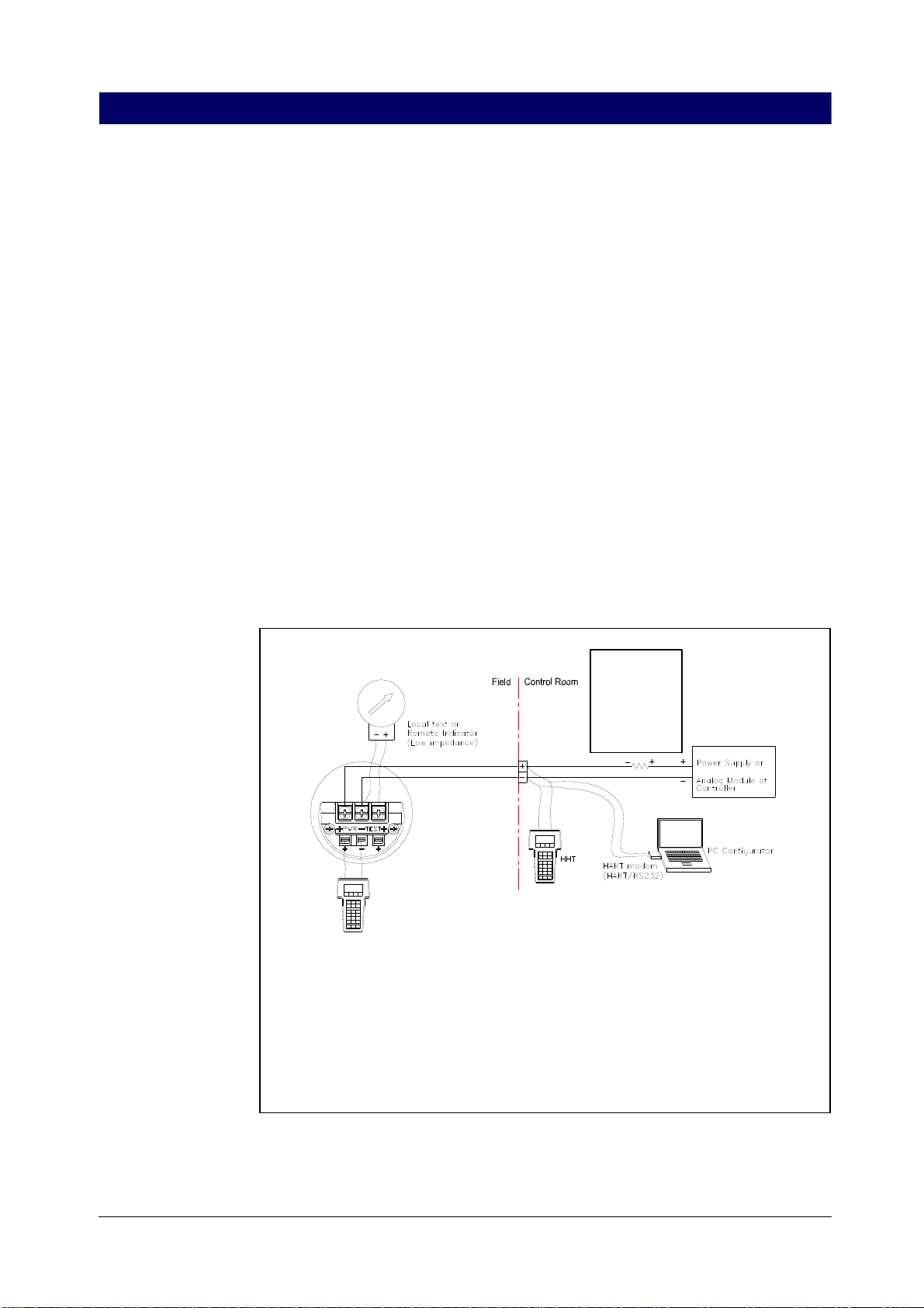
This Transmitter is the 2-wire Loop Powered Transmitter and uses power
line for power supply along with output signal line. In other words,
because 4~20 mA and HART communication signal are sent along the
2-wire for power supply, its installation and Maintenance is easy.
Transmitter can do HART communication with the host control system, HHT
(HART Hand-Held Terminal), or PC and PDA control Software (PC & PDA
Configurator). Therefore, it can execute functions such as change,
configure, test, and calibration of each Transmitter parameter through HART
communication. In the case that Transmitter is connected to analog input
port or output port of control system, it has its own resistance of 250ohm.
Hence, separate loop resistance is unnecessary for HART communication.
In the case that Transmitter is connected to simple 24V DC Power Supply
only, HART communication is enabled by connecting 250~360 Ohm loop
resistance in series.
COMM TESTCOMM TEST
Indicator
Recorder
Controller
DCS..
etc,
250~360 Ohm
(24Vdc)
1.HTT (HART Communicator) or PC Configurator may be connected at any termination
point in the signal loop.
2.HART Communication requires a loop resistance between 250 and 360 ohms(24Vdc).
3.Transmitters operate on 16.0 to 45.0 Vdc transmitter terminal voltage.
[Applied Power]
* 16.0 ~ 45.0 Vdc for general operation
* 21.5 ~ 45.0 Vdc for HART communication ( @ 250 ohm )
* 21.5 ~ 42.0 Vdc for CSA approval ( On Processing )
[Figure 2-4] System Composition Drawing

3
3
3
3
3
3
3
3
3 Directions
Directions
Directions
Directions
Directions
Directions
Directions
Directions
Directions for
for
for
for
for
for
for
for
for handling
handling
handling
handling
handling
handling
handling
handling
handling
3 Directions for handling
Duon System Co., Ltd. 9
Unpacking
Checking
Model and
Specification
Storage
Selection of
installation
location
3 Directions for Handling
This chapter describes directions for handling and storage of Transmitter,
selection of installation location, and insulation, and flameproof structure.
In the event of unpacking Transmitter, be careful not to damage packing
box, the Transmitter and parts in the box, and protector. In the event of
transporting Transmitter to other place, transport after re-packing in the
original state, and be careful not to make a damage during transporting.
The Transmitter model name and specification are indicated on the
nameplate attached to the Transmitter exterior. Check if it is the desired
specification and model.
The following precautions should be observed when the Transmitter is
stored, especially for a long period.
(1) Select a storage area that meets the following conditions:
(a) No exposure to rain or water.
(b) Minimum vibration and shock.
(c) If possible, ambient temperature of 25°C and humidity of 65% RH
is desired, but the condition should at least be
-Ambient
temperature:
-40~85℃ (without LCD module)
-30~80℃ (with LCD module)
-Relative
Humidity:
5%~100% RH (40℃)
(2) Store transmitter in the same packing state of delivery.
(3) In the case of storing a transmitter that has been used, remove every
measuring material from the surfaces of probe and Transmitter. In
particular, when dealing with contaminating materials, handle with care
in accordance with the permitted procedure.
The transmitter is designed to operate under severe environmental
conditions. However, to ensure stable and accurate long term operation,
the following precautions must be observed in selecting an installation
location.

ALT-6100
ALT-6100
ALT-6100
ALT-6100
ALT-6100
ALT-6100
ALT-6100
ALT-6100
ALT-6100 Operation
Operation
Operation
Operation
Operation
Operation
Operation
Operation
Operation Manual
Manual
Manual
Manual
Manual
Manual
Manual
Manual
Manual
ALT-6100 Operation Manual M6100-K01D
M6100-K01D
M6100-K01D
M6100-K01D
M6100-K01D
M6100-K01D
M6100-K01D
M6100-K01D
10 www.autol.com
(1) Avoid locations subject to wide temperature variation or a significant
temperature rate of change. Choose where the operation ambient
temperature of the Transmitter specification is satisfied. If the location
is exposed to severe radiant heat, adequate insulation or ventilation
should be provided.
(2) Select such a place that corrosion does not occur due to chemicals. In
case of installing in a corrosive environment, select such materials for
the Transmitter senor and probe that can withstand the corresponding
corrosive environment. Also, to prevent corrosion due to rain drops
staying in wire pipe, which is not a corrosive environment though, there
has to be appropriate ventilation.
(3) Select an installation site of minimum shock and vibration. In the case
of installing under severe vibration, it is better to install Transmitter
using auxiliary support.
(4) In the case of installing in a flameproof region, select the location
suitable for flameproof standard and check if the Transmitter
certification is appropriate for the corresponding gas.
(5) Select the place maintenance is easy. Maintenance needs a space
where housing can be rotated 180 degree. Also, there should be a
space where you can open terminal block cover and Transmitter front
cover to manipulate interior parts.
NOTE
◈ Transmitter is designed to withstand electric noise of high fre-
quency wave, but if wireless transmitter & receiver is used near
Transmitter or Transmitter exterior wiring, Transmitter may be af-
fected by high frequency wave noise. To test this influence,
observe the noise effect moving the wireless transmitter & re-
ceiver slowly from a long distance of a few meters from
Transmitter. After this observation, always use wireless trans-
mitter & receiver outside the noise effect region only.
4
4
4
4
4
4
4
4
4 Installation
Installation
Installation
Installation
Installation
Installation
Installation
Installation
Installation
4 Installation
Duon System Co., Ltd. 11
4 Installation
Preliminary
Examination
before
Installation
Precautions
This chapter describes installation work and procedure, design drawing,
and considerations at installation of Transmitter.
Prior to installing a Transmitter, read chapter “Selection of Installation
Location” and examine suitability of the installation location.
WARNING
◈ Educated and qualified personnel only are authorized to install
Transmitter.
◈ It is very dangerous and may cause accident for the un-
authorized to handle Transmitter.
◈ When the Transmitter power is on, do not open the Transmitter
cover under Explosive Atmospheres.
◈ Prior to connecting HHT under Explosive Atmosphere, check if
measurement equipments connected to power-line is installed in
accordance with intrinsic safety regulations.
◈ Avoid contact between power-line and terminal. High voltage of
lead wire may cause electric shock.
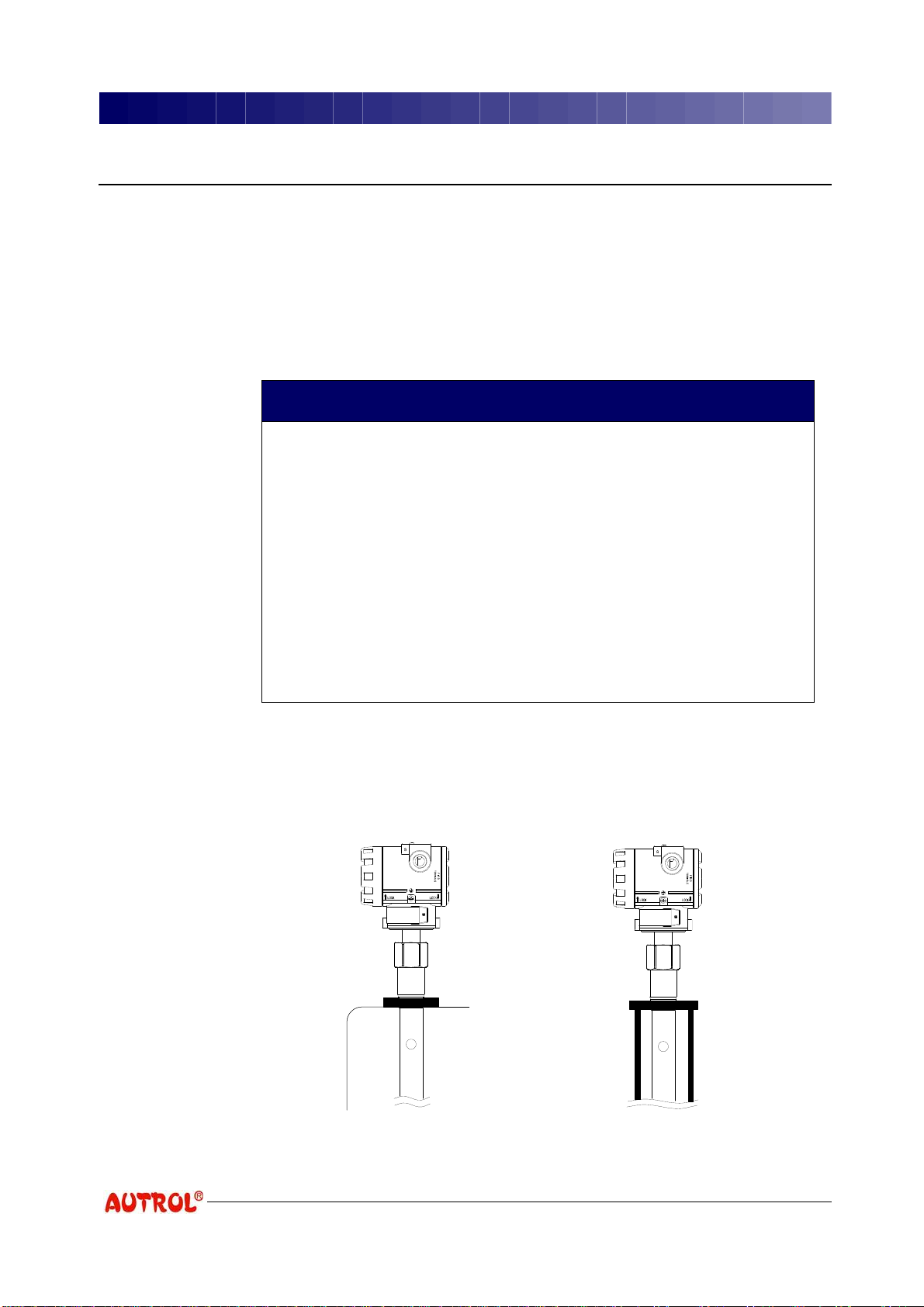
ALT-6100 is easy to mount on tank roof or threaded pipe using thread of
the Transmitter body, and provides various flanges for mounting on nozzle.
Mounting on tank roof. Mounting in threaded pipe.
[Figure 4-1] Threaded Connection
ALT-6100
ALT-6100
ALT-6100
ALT-6100
ALT-6100
ALT-6100
ALT-6100
ALT-6100
ALT-6100 Operation
Operation
Operation
Operation
Operation
Operation
Operation
Operation
Operation Manual
Manual
Manual
Manual
Manual
Manual
Manual
Manual
Manual
ALT-6100 Operation Manual M6100-K01D
M6100-K01D
M6100-K01D
M6100-K01D
M6100-K01D
M6100-K01D
M6100-K01D
M6100-K01D
12 www.autol.com
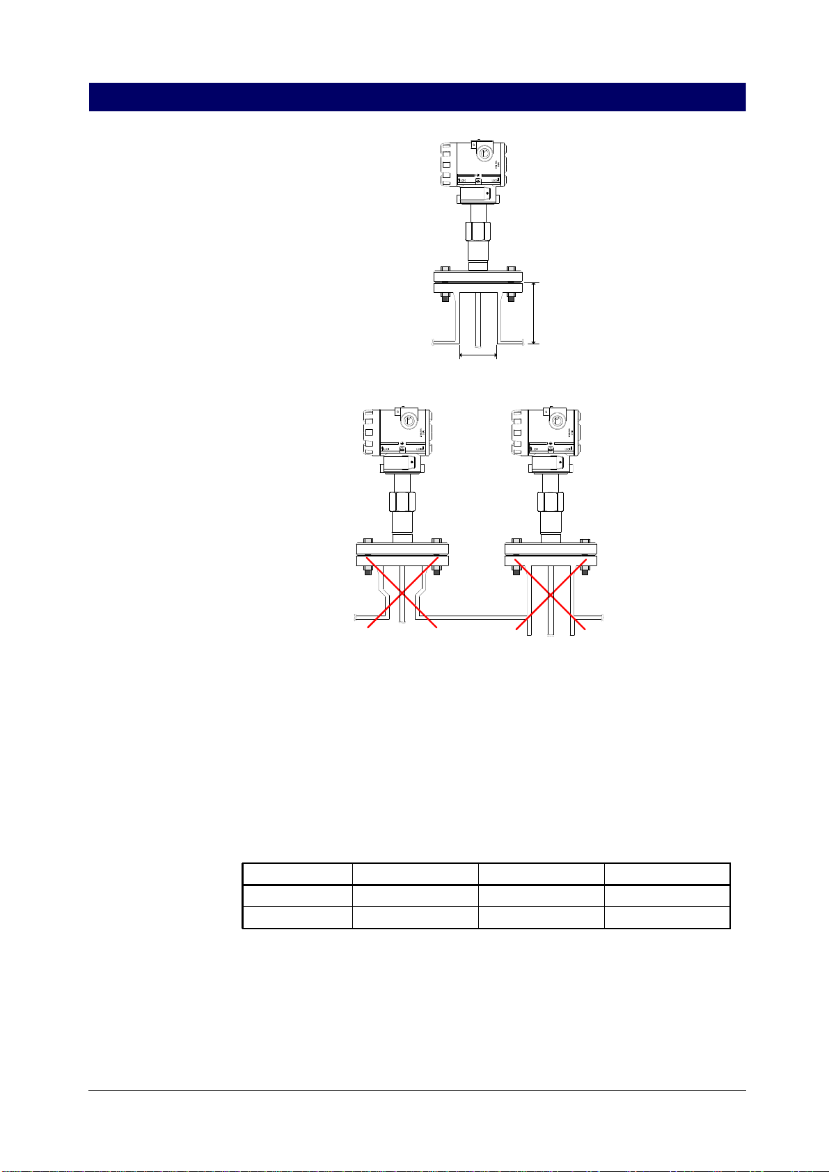
Diameter
Height
Avoid nozzles with reducer
(unless using Coaxial probe) The end of the nozzle must not
have an extension into the tank.
[Figure 4-2] Flange Connection on Nozzles
Transmitter can be mounted on nozzle using a suitable flange. But, the
nozzle should satisfy conditions of Table 4-1 such as minimum diameter
and maximum nozzle height.
[Table 4-1] Minimum nozzle diameter and maximum nozzle height (mm)
Single Rod Twin Rod Coaxial
Diameter MIN. 150 150 >Probe diameter
Heigh MAX. 100 + Diameter 100 + Diameter
Also, the nozzle height should be less than nozzle diameter, if possible,
and the nozzle end should not be extended into Tank.

4
4
4
4
4
4
4
4
4 Installation
Installation
Installation
Installation
Installation
Installation
Installation
Installation
Installation
4 Installation
Duon System Co., Ltd. 13
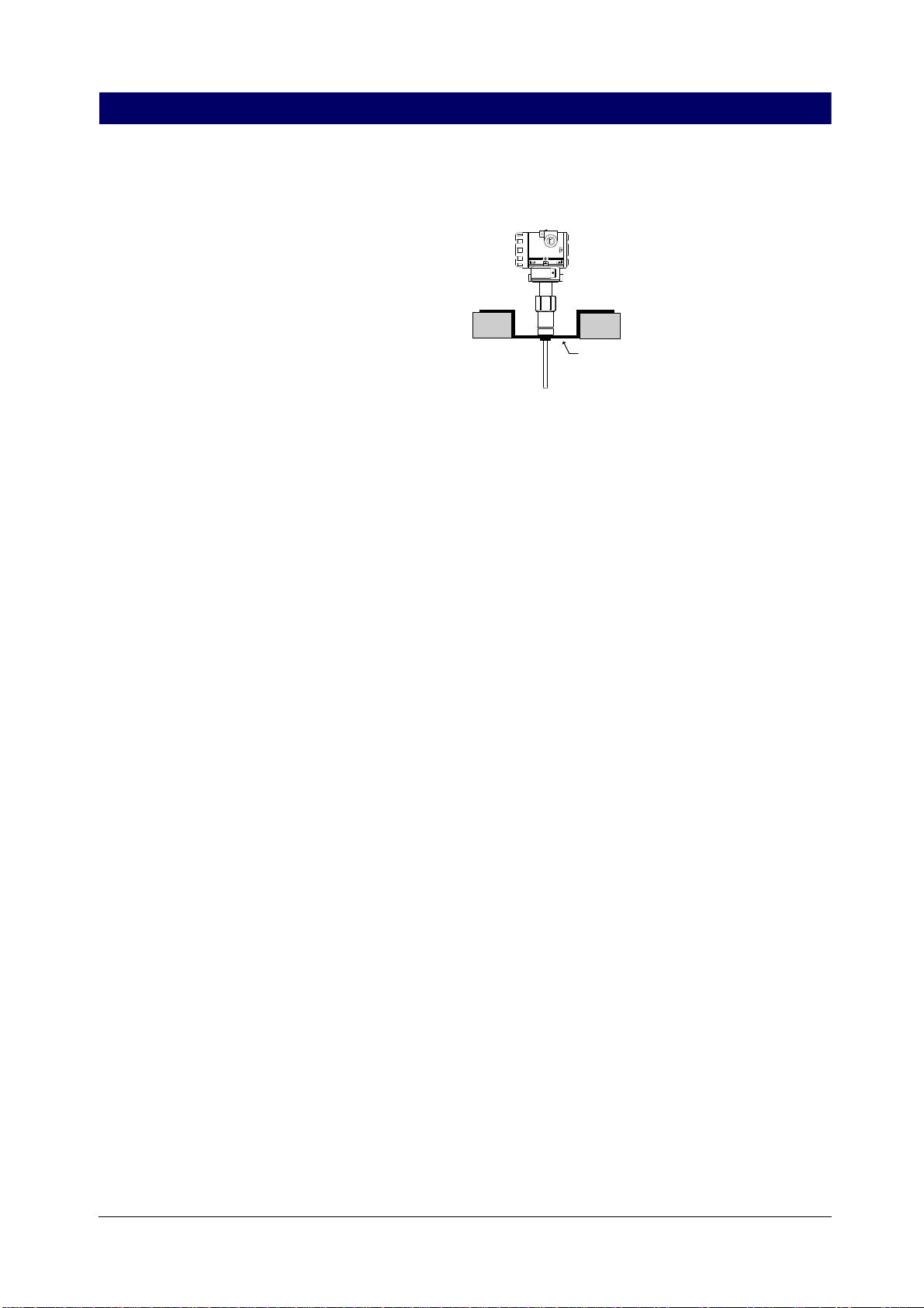
Installation on
Nonmetal Vessel
In case there is a structure over the installation location, Rigid Rod and
Coaxial probe can hardly be inserted for installation. Hence, Flexible probe
should be used.
[Figure 4-3] Installation problems caused by structure
In the case of using a Single Rod probe for nonmetal vessel, metal flange
of at least 2 inches should be used fro optimized performance. To use the
thread connection method for nonmetal vessel, metal sheets should be
installed additionally. But, Coaxial probe can be used limitlessly for
nonmetal vessel.
Metal sheet phi > 8 inch
[Figure 4-4] Installation on nonmetal vessel
ALT-6100
ALT-6100
ALT-6100
ALT-6100
ALT-6100
ALT-6100
ALT-6100
ALT-6100
ALT-6100 Operation
Operation
Operation
Operation
Operation
Operation
Operation
Operation
Operation Manual
Manual
Manual
Manual
Manual
Manual
Manual
Manual
Manual
ALT-6100 Operation Manual M6100-K01D
M6100-K01D
M6100-K01D
M6100-K01D
M6100-K01D
M6100-K01D
M6100-K01D
M6100-K01D
14 www.autol.com
Installation on
Concrete
Solid Measured
Medium
Installation on
Bypass Pipe
In the case of installation on concrete, concrete diameter should be bigger
than concrete width. Otherwise, it can be installed as the Figure below.
Metal
[Figure 4-5] Installation on concrete
In the case that measured medium is solid, Flexible Single Rod probe is
most appropriate, and install in accordance with the following directions:
(1) Prior to installing, vacate Silo.
(2) The probe end should be at least 300 mm above the Silo floor or fixed
on the floor.
(3) Silo and Transmitter earth terminal should earth.
(4) When the flange is used, install without a nozzle, if possible. If any,
the nozzle should be bigger than 100mm.
(5) Install Transmitter at a position that is away from the Tank wall by the
distance of “Tank radius/2", if possible, and the distance should be at
least 500 mm.
Because the medium is solid, the silo roof will get load, and care should
be taken for the followings:
(1) The silo roof should be designed to bear load.
(2) The load is determined by silo size, media density, and friction
coefficient.
(3) Flexural strength of the probe should be checked.
In the following cases, bypass pipe should be installed.
(1) High conductivity bubbles exist in tank.
(2) Severe turbulent exist in tank.
(3) Excessively many complicated structures exist in tank.
4
4
4
4
4
4
4
4
4 Installation
Installation
Installation
Installation
Installation
Installation
Installation
Installation
Installation
4 Installation
Duon System Co., Ltd. 15
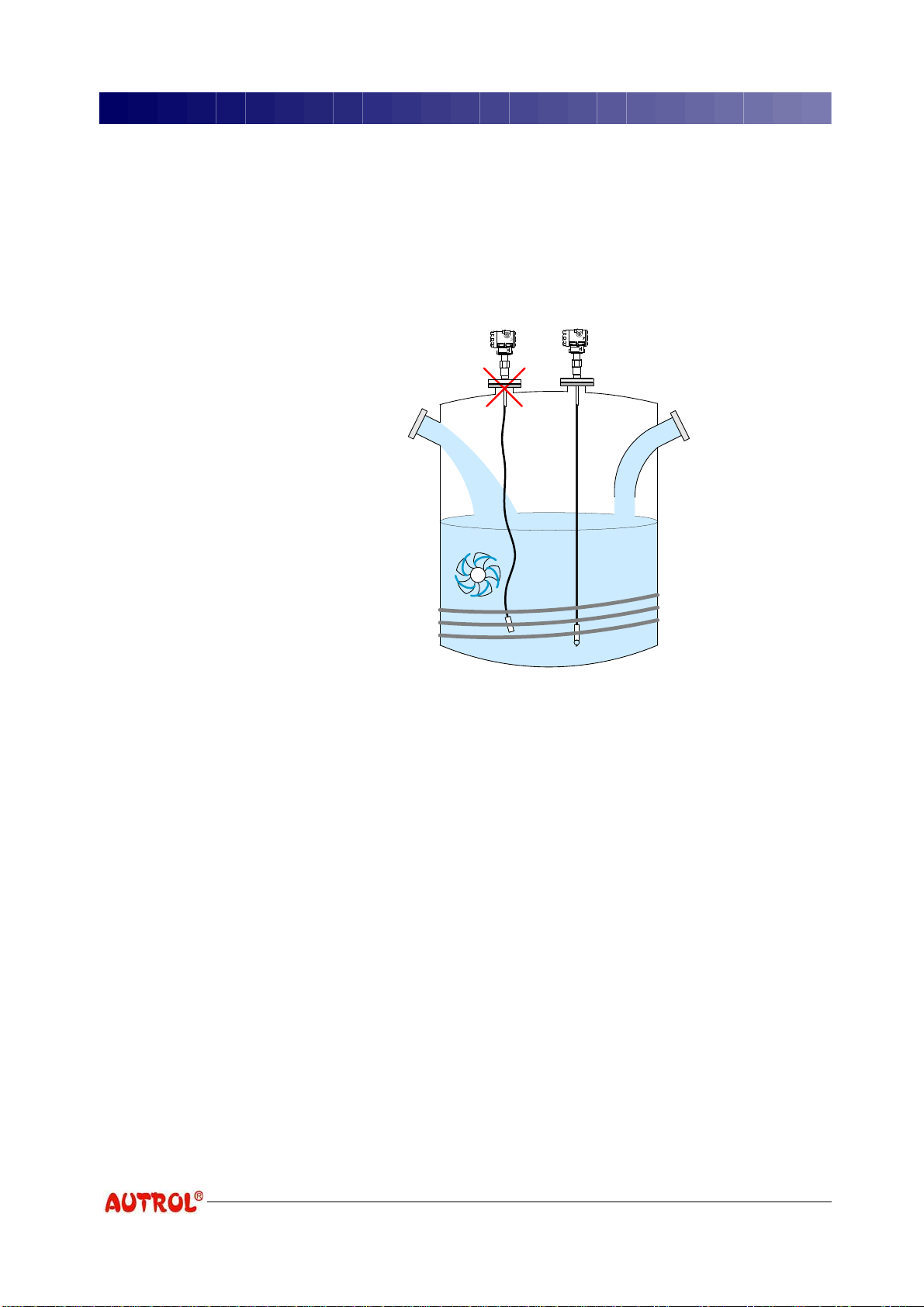
Liquid Measured
Medium
In the case of using Flexible and Rigid Rod probe, the bypass pipe
diameter should be bigger than 100mm.
The mounting location of Transmitter should be determined carefully
considering the interior state of Tank. Transmitter should be installed where
the influence of obstacles is minimized.
Agitator
Inlet pipe
Heating coils
Deflector pipe
[Figure 4-6] Condition of Tank interior
On mounting Transmitter, be careful about the followings:
(1) Do not install near the process inlet pipe.
(2) Do not install near agitator.
(3) In case turbulence occurs inside Tank, probe should be fixed on the floor.
(4) Do not install near heating coil.
(5) Prevent probe from contacting nozzle and other objects.
(6) In the case of using Flexible probe, stretch it tight to keep it parallel
with the Tank wall, and secure the distance from wall to at least
100mm (longer than 300mm is recommended).
(7) In case it is installed near the process inlet pipe, deflector pipe should
be installed.
(8) In case nozzle may develop build-up, install without nozzle.
Table of contents
Other Autrol Transmitter manuals

Autrol
Autrol ATT2100 User manual

Autrol
Autrol APT 3000 Series User manual

Autrol
Autrol APT3200 Series User manual

Autrol
Autrol ATT Series User manual

Autrol
Autrol APT3200 Series User manual

Autrol
Autrol APT 3100 Series User manual

Autrol
Autrol APT3200 Series User manual

Autrol
Autrol APT 3100 Series User manual


