AV TOOL AVT-8120 User manual

Instruction Manual
AVT-8120
Quad Splitter

2

3
Table Of Contents
1.0 Introduction 4
2.0 Specifications 5
3.0 Package Contents 6
4.0 Connecting the Hardware 7
5.0 Operating The Unit 7
6.0 Troubleshooting 18
7.0 Limited Warranty 18
8.0 Regulatory Compliance 19
9.0 Contact Information 20

4
1.0 INTRODUCTION
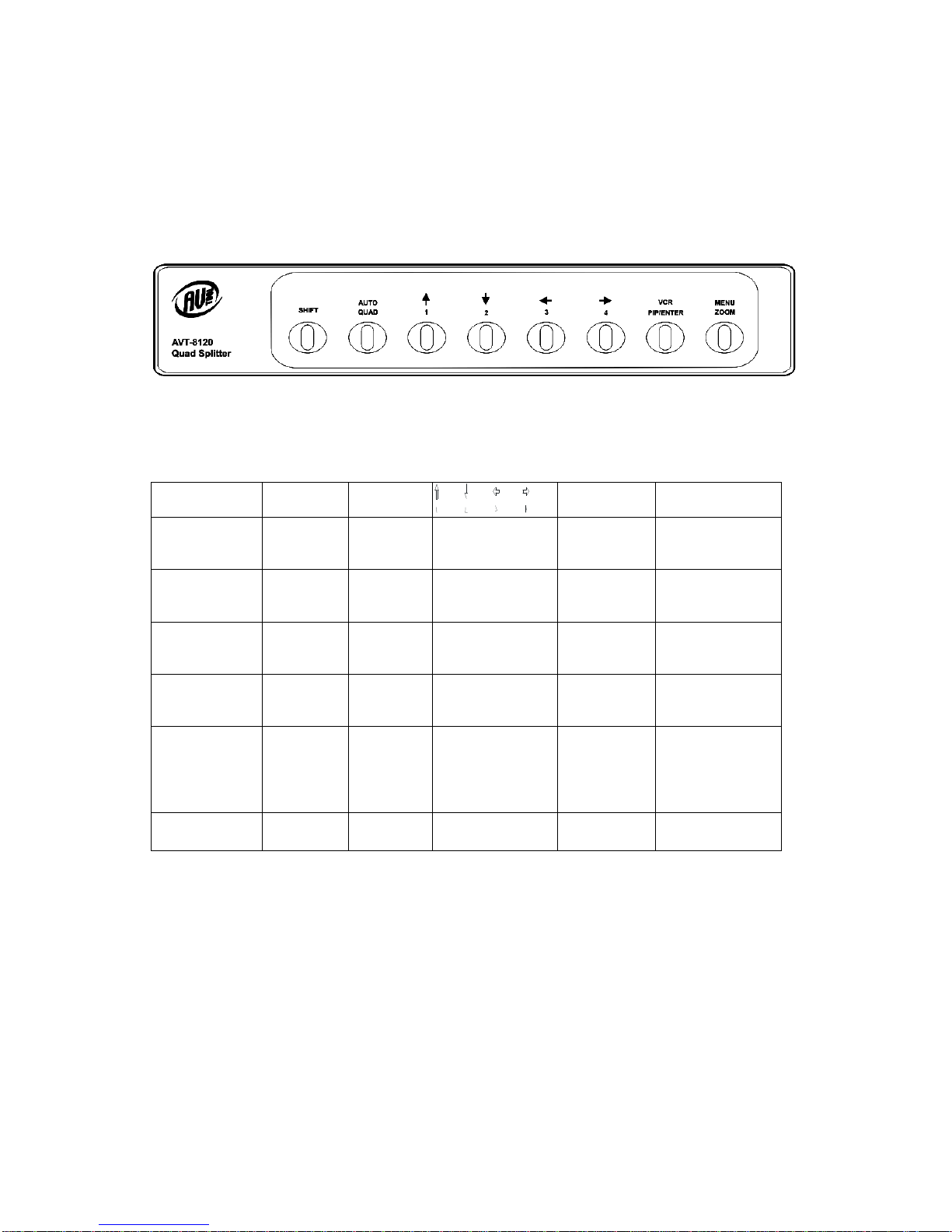
Thanks for purchasing this AVT-8120 Quad Splitter product from AV Toolbox.
The AVT-8120 is designed to provide real time, high quality display of up to four
video inputs on one screen or the sequential display of up to four inputs full
screen. The unit will accept an input from a VCR for display on the main monitor
and also provides an output to a VCR for recording camera images. AV Toolbox
offers a full line of high quality Standards Converters, Up-Converters, Scan
Converters, Distribution Amplifiers, Routing Switchers, Time Base Correctors,
PIP Display Devices, Quad Splitters and Video Conditioners. RF Modulators,
Digital Audio Converters, LCD Monitors/Receivers and Multimedia Cables round
out the product offerings.
1.1 Liability Statement
Every effort has been made to ensure that this product is free of errors. AV
Toolbox cannot be held liable for the use of this hardware or any direct or indirect
consequential damages arising from its use. It is the responsibility of the user of
the hardware to check that it is suitable for his/her requirements and that it is
installed correctly. All rights reserved. No parts of this manual may be
reproduced or transmitted by any form or means electronic or mechanical,
including photocopying, recording or by any information storage or retrieval
system without the written consent of the publisher.
AV Toolbox reserves the right to revise any of its hardware and software
following its policy to modify and/or improve its products where necessary or
desirable. This statement does not affect the legal rights of the user in any way.
All third party trademarks and copyrights are recognised. The AV Toolbox Logo,
TV One Logo, TV One-Task and CORIO are the registered Trademarks of TV
One. All other trademarks are the property of their respective holders.
1.2 FEATURES
The AVT-8120 Quad Splitter has many features that enable it to perform in a
superior manner. Among those features you will find:
Video Inputs: 4x Composite Video (CV) + 1x VCR (CV)
Video Input Loop-thru provided
Video Outputs: 1x Composite Video (CV) + 1x VCR (CV)
Built in Time Base Corrector
Maximum Video Images: 4
Maximum Image Positions: 9
Automatic Video Gain Control (Each Channel)
NTSC or PAL
Built in Sequential Switcher

5
2.0 SPECIFICATIONS
Video Input Connectors
Composite Video (Camera) Inputs 4x BNC Female
Composite Video (VCR) Input 1x BNC Female
Video Output Connectors
Composite Video 4x BNCFemale (Input Loop Thru)
Monitor Video 1x BNC Female
Composite Video to VCR 1x BNC Female
Alarm Output
Alarm Contact Closures 9 Pin D-Sub Connector
Alarm Signal Specification 5 VDC@50ma (Non-inductive load)
Input Signal Characteristics
Inputs Supported 4x Composite Video (Looping)
Output Signal Characteristics
Output Supported 2x Composite Video
Control Methods
Local Front Panel Mounted Push Button Switches
Mechanical
Size (H-W-D) 2.04”x9.37”x8.21” (51.7mmx238mmx208.5mm)
Weight (Net) 2.86. Lbs (1.3kg)
Temperature Range
Operating Temperature +32° to 122° F (0° to 50° C)
Storage Temperature -4° to 158° F (-20° to 70° C)
Warranty
Limited Warranty 1 Year, Parts and Labor
Power Requirements
External AC Adaptor 12 VDC/500ma US, UK or EURO AC Plug
Regulatory Approvals
AVT-8120 FCC, CE
AC Power Adaptor UL, CE, CSA
Accessories Included 1x AC Power Adapter
1x Instruction Manual
1x Alarm Connector Jack
Alarm Connector Pinout:
9 8 7 6
5 4 3 2 1 1. ALARM #1 6. NC
2. ALARM #2 7. COM
3. ALARM #3 8. NO
4. ALARM #4 9.GND
5. 5V

6
3.0 CHECKING PACKAGE CONTENTS
Before attempting to use this unit, please check the packaging and make certain
the following items are contained in the shipping carton:
1x AVT-8120 Quad Splitter
1x AC Power Adapter
1x Alarm Connector
1x Operations Manual
Note: Please retain the original packing material should the need ever arise to
return the unit. If you find any items are missing, contact your reseller or AV
Toolbox immediately. Have the Model Number, Serial Number and Invoice
available for reference when you call.

7
4.0 CONNECTING THE HARDWARE
Please study the drawings below and become familiar with the inputs, outputs
and control locations on the AVT-8120.
AVT-8120 Front Panel
The front panel of the AVT-8120 contains the product’s control switches and On
Screen Display (OSD) menu access.
AVT-8120 Rear Panel
On the AVT-8120, the power connector, video in connectors, 75Ωdip switch
selector for video termination, monitor out, power on and off, VCR in and out plus
the alarm connector are located on the rear of the unit.
5.0 OPERATING THE AVT-8120
First, prepare the alarm cable if you intend to utilize this capability of the unit.
(Consult the information on the specification page [page 5] to determine the
wiring diagram and the voltage and current specifications used for the alarm
circuits.) When finished, connect the alarm connector to the AVT-8120 and then
to the external alarm devices.
Next, attach up to four cameras to the unit’s video inputs. If you are not looping
the video inputs to individual video monitors, use the 75Ωvideo termination dip
switch to terminate the inputs. Attach a video cable from the video output jack to
your quad split monitor. Connect the VCR in and out cables. Next, connect the
supplied AC adaptor to the unit and then to the AC power source. Turn on any

8
additional monitors and the cameras. At this time, an image should be present on
your master monitor.
Looking at the front of the unit, you’ll see several control switches. The switches
work in concert with one another in some instances and the table below will help
you understand the functions utilized by the AVT-8120’s controls.
The table below shows the various possible modes in the left most column and
the balance of the columns show what happens when you press the various
buttons when in the selected mode.
At this time, become familiar with the different types of operating modes by
pressing the various keys.
Because there are several modes and adjustments possible, the task appears
daunting at first but once you start exploring the various functions it will become
clear very quickly.
Look at the top row – the Normal Mode row. If you are in the Normal Mode,
pressing the various buttons (Shift, Auto/Quad. The Arrow Keys, VCR/PIP/Enter
Mode SHIFT AUTO /
QUAD VCR / PIP /
ENTER MENU / ZOOM
Normal Mode
(Live display) Go to shift
mode 4-Split
Mode
button
Camera 1,2,3,4
Full screen
display
PIP screen
display Picture 2 x 2
zoom in
Shift Mode
(Press Shift
Key)
Go To
normal
mode
Channel
sequence Camera 1,2,3,4
Full screen
display
Go to VCR
Mode Go to Menu Setup
Menu Mode
(Menu function
page)
Reduce
value Increase
value
UP/DOWN / LEFT
/ RIGHT direction
button
ENTER key Exit Menu
VCR Mode No function 4-Split
Mode
button
Camera 1,2,3,4
Full screen
display
Go to Shift
mode Go to Menu Setup
PIP Mode Go to Shift
+ PIP mode Go to
normal
mode quad
UP / DOWN,
main-screen PIP
move, LEFT /
RIGHT, on-
screen
PIP move
Go to normal
mode 2 x 2 zoom in
SHIFT + PIP
mode Go to PIP
mode PIP auto
sequence PIP-screen
moving Go to VCR
mode Go to MENU
mode

9
and Menu/Zoom) will perform the functions listed in the boxes beneath the
captions. As an example, pressing the VCR/PIP/ENTER key will cause the unit to
enter the PIP screen display mode. Pressing the Auto/Quad button will return the
unit to the Quad Split mode and so on.
Each mode listed at the left hand side of the table has actions associated with
that mode and those actions are listed in the boxes to the right of the mode.
In addition to seeing changes to the video on the monitor as you change modes,
if you select the Menu Mode (by pressing the shift key and the Menu/Zoom key),
you’ll see the On Screen Display (OSD) appear which will guide you through all
the setup functions.
As an example of how this process works, press the shift key and the
Menu/zoom key. As shown above, this will take you to the Menu Function Set Up
screen on the monitor.
5.1 FUNCTION SETUP (SHIFT + MENU / ZOOM)
1. DISPLAY SETUP Display items
2. CAMERA SETUP Camera related setup
3. BUZZER SETUP Buzzer on or off setup
4. DATE-TIME SETUP Current time and date setup
5. ALARM SETUP Alarm function setup
6. MOTION SETUP Motion function setup
7. EVENT LIST Event list page
8. SYSTEM SETUP System setup page
Move cursor to the desired item and then press ENTER to reach the desired
sub-menu.
FUNCTION SETUP
1. DISPLAY SETUP
2. CAMERA SETUP
3.BUZZER SETUP
4.DATE-TIME SETUP
5.ALARM SETUP
6.MOTION SETUP
7.EVENT LIST
8.SYSTEM SETUP
** VERSIONXXX **
2004/12/14 10:37

10
5.2 DISPLAY SETUP
Item Description Value
DATE-TIME Current date and time display on the screen? ON / OFF
CAMERA TITLE Camera title display on the screen? ON / OFF
VCR DATE-TIME Date and Time record to VCR? ON / OFF
VCR CAMERA TITLE Camera Title record to VCR? ON / OFF
BORDER SET Quad split border color? WHITE / BLACK /
DARK / GRAY
Move cursor to the desired item and then press ENTER to reach the desired
Menu item.
The Shift and AUTO / QUAD keys are used to change values.
NOTE: Any time you make a change to a value while in the menu mode, you
must press the Enter key to save the change. Making a change without pressing
the Enter key may result in a change being made but the change will be lost
when you remove power from the unit unless you have first pressed the Enter
key immediately after making the change.
FUNCTION SETUP
1. DISPLAY
2. CAMERA SETUP
3. BUZZER SETUP
4. DATE-TIME SETUP
5. ALARM SETUP
6. MOTION SETUP
7. EVENT LIST
8. SYSTEM SETUP
** VERSION 0.07 **"
DISPLAY SETUP
1. DATE-TIME ON
2. CAMERA TITLE ON
3. VCR DATE-TIME ON
4. VCR CAMERA TITLE ON
5. BORDER SET WHITE

11
5.3 CAMERA SETUP
CAMERA SETUP PAGE
CHANNEL NUMBER CH 01 / 02 / 03 / 04
Item Value
BRIGHTNESS -31 ~ +32
CONTRAST -31 ~ +32
SATURATION -31 ~ +32
HUE -31 ~ +32
GAIN -31 ~ +32
TITLE CAM0100000
DEFAULT RESET Press ENTER
Move cursor to the desired item and then press ENTER to reach the desired
Menu item.
The Shift and AUTO / QUAD keys are used to change values.
FUNCTION SETUP
1. DISPLAY SETUP
2. CAMERA SETUP
3. BUZZER SETUP
4. DATE-TIME SETUP
5. ALARM SETUP
6. MOTION SETUP
7. EVENT LIST
8. SYSTEM SETUP
** VERSION 0.07 **"
CAMERA SETUP PAGE
** CHANNEL NUMBER
1. BRIGHTNESS 00
2. CONTRAST 00
3.SATURATION 00
4. HUE 00
5. GAIN 00
6. TITLE
7. DEFAULT RESET
MENU,ESC:EXIT, :MODIFY
** CAUTION**
ALL CAMERA SETUP VALUE WILL BE
CLEAR AND RESTORE FACTORY DEFAULT
PRESS [ENTER] TO RESTORE
PRESS [MENU] TO CANCEL

12
5.4 BUZZER SETUP
Item Description Value
SYSTEM BUZZER Buzzer Function ON / OFF
BUTTON BUZZER Key pressed buzzer. ON / OFF
ALARM BUZZER Alarm trigger buzzer. ON / OFF
MOTION BUZZER Movement detected
buzzer. ON / OFF
V-LOSS BUZZER Video loss buzzer. ON / OFF
Move cursor to the desired item and then press ENTER to reach the desired
Menu item.
The Shift and AUTO / QUAD keys are used to change values.
FUNCTION SETUP
1. DISPLAY SETUP
2. CAMERA SETUP
3. BUZZER SETUP
4. DATE-TIME SETUP
5. ALARM SETUP
6. MOTION SETUP
7. EVENT LIST
8. SYSTEM SETUP
** VERSION 0.07 **"
BUZZER SETUP PAGE
**SYSTEM BUZZER ON
BUTTON BUZZER ON
ALARM BUZZER ON
MOTION BUZZER ON
VLOSS BUZZER ON

13
5.5 DATE-TIME
DATE : Current Year / Month / Day
TIME : Current Hour / Minute / Second
Move cursor to the desired item and then press ENTER and then use the
Shift and AUTO / QUAD keys are used to change values. Press ENTER again to
accept the change.
FUNCTION SETUP
1. DISPLAY SETUP
2. CAMERA SETUP
3. BUZZER SETUP
4. DATE-TIME SETUP
5. ALARM SETUP
6. MOTION SETUP
7. EVENT LIST
8. SYSTEM SETUP
** VERSION 0.07 **"
DATE-TIME SETUP PAGE
1.DATE 2000/00/00
2.TIME 12:12:12

14
5.6 ALARM SETUP
ALARM SETUP PAGE (Alarm sensor type and duration time setup)
ALARM SIGNAL1: NO / NC / OFF
ALARM SIGNAL2: NO / NC / OFF
ALARM SIGNAL3: NO / NC / OFF
ALARM SIGNAL4: NO / NC / OFF
ALARM DURATION: 000 ~ 999 SEC
Move cursor to the desired item and then press ENTER to reach the desired
Menu item.
The Shift and AUTO / QUAD keys are used to change values.
ALARM SETUP PAGE
1.ALARM SIGNAL1:
2.ALARM SIGNAL2:
3.ALARM SIGNAL3:
4.ALARM SIGNAL4:
5.ALARM DURATION: SEC
FUNCTION SETUP
1. DISPLAY SETUP
2. CAMERA SETUP
3. BUZZER SETUP
4. DATE-TIME SETUP
5. ALARM SETUP
6. MOTION SETUP
7. EVENT LIST
8. SYSTEM SETUP
** VERSION 0.07 **"

15
5.7 MOTION SETUP
MOTION SETUP PAGE
**MOTION FUNCTION ON / OFF
**CHANNEL NUMBER CH 01 / 02 / 03 / 04
Move cursor to the desired item and then press ENTER to reach the desired
Menu item.
The Shift and AUTO / QUAD keys are used to change values.
Item Value Description
SENSITIVITY 0 ~ +15 Object motion sensitivity setup
VELOCITY 0 ~ +30 Object motion speed setup
MOTION ACTIVE ON / OFF Channel motion detect active
MOTION AREA SETUP Motion area: transparent window lattice
means unit is detecting, blue window lattice
means unit is not detecting.
FUNCTION SETUP
1. DISPLAY SETUP
2. CAMERA SETUP
3. BUZZER SETUP
4. DATE-TIME SETUP
5. ALARM SETUP
6. MOTION SETUP
7. EVENT LIST
8. SYSTEM SETUP
** VERSION 0.07 **"
MOTION SETUP PAGE
**MOTION FUNCTION
**CHANNEL NUMBER
1.SENSITIVITY
2.VELOCITY
3.MOTION ACTIVE
4.MOTION AREA SETUP

16
5.8 EVENT LIST
Event list.
Menu page display event list such as v-loss, alarm, and motion list.
10 events and 10 pages display. Total 100 entries.
FUNCTION SETUP
1. DISPLAY SETUP
2. CAMERA SETUP
3. BUZZER SETUP
4. DATE-TIME SETUP
5. ALARM SETUP
6. MOTION SETUP
7. EVENT LIST
8. SYSTEM SETUP
** VERSION 0.07 **"
EVENT LIST PAGE
NO OCCURED TIME CH TYPE

17
5.9 SYSTEM SETUP
SYSTEM SETUP PAGE
DWELL INTERVAL: 001 ~ 999 SEC (Channel auto sequence time setup.)
CLEAN EVENT TABLE
FACTORY DEFAULT: Press ENTER (Reverts back to factory default.)
Move cursor to the desired item and then press ENTER to reach the desired
Menu item.
The Shift and AUTO / QUAD keys are used to change values.
SYSTEM SETUP PAGE
1.DWELL INTERVAL: SEC
2.CLEAN EVENT TABLE
3.FACTORY DEFAULT
FUNCTION SETUP
1. DISPLAY SETUP
2. CAMERA SETUP
3. BUZZER SETUP
4. DATE-TIME SETUP
5. ALARM SETUP
6. MOTION SETUP
7. EVENT LIST
8. SYSTEM SETUP
** VERSION 0.07 **"
** CAUTION **
ALL SETUP VALUE WILL BE CLEAR,
AND RESTORE FACTORY DEFAULT
PRESS [ENTER] TO RESTORE.
PRESS [MENU] TO CANCLE.
** CAUTION **
ALL EVENT VALUE WILL BE CLEAR,
PRESS [ENTER] TO CLEAR.
PRESS [MENU] TO CANCLE.

18
6.0 Troubleshooting
Other than checking for faulty cables, the most common problem would be
becoming confused as to the function of the modes and keys. Re-read the
operational tutorial above to make certain you understand what each button does
for each mode. Make sure the AVT-8120 is connected to a known good monitor
and the camera inputs are present. If not using the camera loop through feature,
make sure the terminator DIP switch is switched to ‘On’ for each input source. If
one input image is acceptable but the other is not acceptable, you should
suspect faulty cables. Swap the cables to determine if the problem also swaps.
After trying the above suggestions should the problem still persist, contact your
dealer for additional suggestions before contacting AV Toolbox’s parent
company, TV One. Please contact TV One via our support website:
http://tvone.crmdesk.com. Create a technical support request on the site and
our support team will respond within a short period of time.
7.0 LIMITED WARRANTY
LIMITED WARRANTY – With the exceptions noted in the next paragraph, AV
Toolbox warrants the original purchaser that the equipment it manufactures or
sells will be free from defects in materials and workmanship for a period of one
year from the date of purchase. Should this product, in AV Toolbox’s opinion,
prove defective within this warranty period, AV Toolbox, at its option, will repair or
replace this product without charge. Any defective parts replaced become the
property of AV Toolbox. This warranty does not apply to those products which
have been damaged due to accident, unauthorized alterations, improper repair,
modifications, inadequate maintenance and care, or use in any manner for which
the product was not originally intended.
Items integrated into AV Toolbox products that are made by other manufacturers,
notably computer hard drives and liquid crystal display panels, are limited to the
term of the warranty offered by the respective manufacturers. Such specific
warranties are available upon request to AV Toolbox. If repairs are necessary
under this warranty policy, the original purchaser must obtain a Return
Authorization Number from AV Toolbox and return the product to a location
designated by AV Toolbox, freight prepaid. After repairs are complete, the
product will be returned, freight prepaid.
LIMITATIONS - All products sold are "as is" and the above Limited Warranty is
in lieu of all other warranties for this product, expressed or implied, and is strictly
limited to one year from the date of purchase. AV Toolbox assumes no liability to
distributors, resellers or end-users or any third parties for any loss of use,
revenue or profit.
AV Toolbox makes no other representation of warranty as to fitness for the
purpose or merchantability or otherwise in respect of any of the products sold.

19
The liability of AV Toolbox with respect to any defective products will be limited to
the repair or replacement of such products. In no event shall AV Toolbox be
responsible or liable for any damage arising from the use of such defective
products whether such damages be direct, indirect, consequential or otherwise,
and whether such damages are incurred by the reseller, end-user or any third
party.
8.0 REGULATORY COMPLIANCE
The AVT-8120 has been tested for compliance with appropriate FCC and CE
rules and regulations. The Power Adaptor/Supplies have been tested for
compliance with appropriate UL, CUL, CE, PSE, GS Rules, Regulations and/or
Guidelines. These Products and Power Adapters are RoHS Compliant.
9.0 CONTACT INFORMATION
Should you have questions or require assistance with this product in areas not
covered by this manual, please contact TV One at the appropriate location.

20
AV Toolbox USA
2791 Circleport Drive
Erlanger, KY 41018
USA
Tel 800-235-3280
Tel 859-647-1077
Fax 859-282-8225
www.avtoolbox.com
AV Toolbox Europe
Continental Approach
Westwood Industrial Estate
Margate, Kent CT9 4JG, UK
Tel +44 (0)1843 873307
Fax +44 (0)1843 873312
www.avtoolbox.com
AV Toolbox Latin America
6991 NW 82nd Avenue #8
Miami, FL 33166
USA
Tel 305-396-6275
Fax 305-418-9306
www.tvonela.com
AV Toolbox Mercosur
Av. Diaz Velez 3965 #PB
(1200) Capital Federal
Buenos Aires, Argentina
Tel +54 11 5917-2525
Fax +54 11 4032-0281
www.tvonela.com
AV Toolbox Asia
16F-4, No.75, Sec.1
Hsin Tai Wu Rd., Hsichih
Taipei Hsien 22101
Taiwan R.O.C.
Tel +886 2 2698-2296
Fax +886 2 2698-2297
www.tvoneasia.com
AV Toolbox China
Room 1007, Golden Peach Building
No. 1900 Shangcheng Road
Pudong, Shanghai
China 200120
Tel +86 21 5830-2960
Fax +86 21 5851-7949
www.tvoneasia.com
End of Manual
Table of contents
Other AV TOOL Cables And Connectors manuals
Popular Cables And Connectors manuals by other brands

cable matters
cable matters 202031 quick start guide

Gomax
Gomax SP-5018P user manual

Winegard
Winegard CSK-300 quick start guide

ROPES RARK EQUIPMENT
ROPES RARK EQUIPMENT LOCKDCLOPS Tweezle O instruction manual

Festo
Festo NEBM-H6G4 Q13 LE4 Series Assembly instructions

Paradyne
Paradyne 9261 installation instructions