Avalon VT-747SP User manual

DESIGNAVALON
PURE CLASS A MUSIC RECORDING SYSTEMS
VT-747SP
Operation Manual
Pure Class A Stereo Spectral Opto-Compressor Equalizer
© 2001 Avalon Industries Incorporated. Release 1.0.

AVALON DESIGN
PURE CLASS A MUSIC RECORDING SYSTEMS
VT-747SP
Operation Manual
Avalon Industries, Inc., PO Box 59 6, San Clemente, CA 926 3
Tel: 949-492-2000 Fax: 949-492-4284 www.avalondesign.com

AVALON DESIGN
PURE CLASS A MUSIC RECORDING SYSTEMS
Table of Contents
1.0 Introduction . . . . . . . . . . . . . . . . . . .4
1.1 Overview . . . . . . . . . . . . . . . . . . .4
1.2 Features . . . . . . . . . . . . . . . . . . . .5
1.3 Unpacking and Inspection . . . . . . .6
2.0 Quic Start-up . . . . . . . . . . . . . . . . .7
2.1 Quick Set-up Guide . . . . . . . . . . .8
2.2 Tips . . . . . . . . . . . . . . . . . . . . . . .9
2.3 Tutorial-Using it all . . . . . . . . . . . .9
3.0 Safety and Grounding . . . . . . . . . .10
3.1 Safety Instructions . . . . . . . . . . .10
3.2 Grounding Instructions . . . . . . . .10
3.3 AC Voltage Selection . . . . . . . . . .11
3.4 Fuse Replacement . . . . . . . . . . .12
3.4 Rack Mounting and Cooling . . . .12
3.5 Turn-on Procedure . . . . . . . . . . .13
4.0 Operation and Controls . . . . . . . . .14
4.1 Rear Panel Description . . . . . . . .1
4.2 Connections . . . . . . . . . . . . . . . .1
4.3 Unbalanced Operation . . . . . . . .1
4.4 Using the Vt- 4 sp . . . . . . . . . . .18
4.5 Six Band Passive Equalizer . . . .18
4.6 Using the Equalizer . . . . . . . . . . .18
4. Using the Side-chain . . . . . . . . . .19
5.0 Applications . . . . . . . . . . . . . . . . . .19
5.1.0 Typical Set-ups . . . . . . . . . . . .19
5.1.1 Recording . . . . . . . . . . . . . . . . . . .20
5.1.2 Stereo Mixdown (Buss) . . . . . . . . .20
5.1.3 Mixdown/Mastering - DAW . . . . . . .20
5.1.4 Mastering . . . . . . . . . . . . . . . . . . .21
5.2.0 Application Settings . . . . . . . . .21
5.2.1 Stereo Buss for Mixdown . . . . . . . .21
5.2.2 Stereo Buss with De-ess . . . . . . . .22
5.2.3 De-ess on Vocals . . . . . . . . . . . . .22
5.2.4 Stereo Keyboards . . . . . . . . . . . . .23
5.2.5 Extreme Compression Effect . . . . .23
5.2.6 Acoustic Piano . . . . . . . . . . . . . . . .24
5.2. Acoustic Guitar . . . . . . . . . . . . . . .24
5.2.8 Drum Overheads . . . . . . . . . . . . . .25
6.0 Compression Primer . . . . . . . . . . .25
6.1 Equalization Primer . . . . . . . . . . . .27
7.0 FAQs . . . . . . . . . . . . . . . . . . . . . . . .27
8.0 Trouble Shooting . . . . . . . . . . . . . .30
9.0 Service and Contact Information . .32
10.0 Technical Information . . . . . . . . .33
10.1 Recall Sheet . . . . . . . . . . . . . . .34
10.2 Block Diagram . . . . . . . . . . . . .35
11.0 Warranty . . . . . . . . . . . . . . . . . . . .36
11.1 Returns . . . . . . . . . . . . . . . . . . .36
12.0 Safety Standards . . . . . . . . . . . . .36
Appendix A - Glossary . . . . . . . . . . . . .37

Page 4 Avalon Vt-747sp Operation Manual
AVALON DESIGN
Introduction
1.0 Introduction
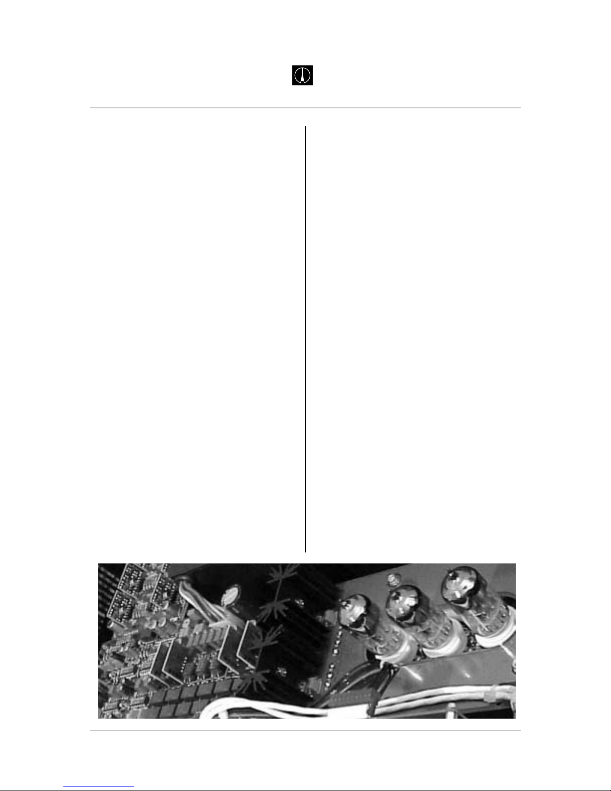
Welcome to Avalon and the world of high
performance Pure Class A music recording
systems. The Vt-747sp is an extremely
versatile, pure Class A, vacuum tube/discrete
TSP (Tube Signal Path) stereo opto-
compressor and program equalizer.
The Vt-747sp is the most creative and flexible
stereo compressor available. With TSP (Tube
Signal Path), the Vt-747sp uses three hand
selected vacuum tubes in the signal path for
warm tube tone or bypasses the tubes for
classic Class Adiscrete transistor sound. Also
featured on the Vt-747sp is a passive six-
band graphic equalizer for gentle tone-
shaping plus a two-band parametric EQ for
complete spectral side-chain or musical
control.
The Vt-747sp is hand built in the USA using
only the finest active and passive electronic
components available. Many of these parts
have been custom-manufactured exclusively
for Avalon. A "no compromise" approach in
every stage of design and production ensures
that the Vt-747sp will give many years of
dependable high-quality service.
Please take a moment to read this manual
and enjoy your Avalon experience!
1.1 Overview
The Vt-747sp combines a stereo tube/
discrete Class A opto-compressor with a
musical six-band program equalizer, as well
as Left/Right output level, gain reduction
metering and an internal regulated power
supply in a 2U space. Ideal for high
performance DAW (digital audio workstation)
input signal conditioning, stereo buss
compression/EQ, stereo keyboards and
mastering applications.
The Vt-747sp features a minimum signal path
design utilizing sealed silver relays for all
signal routing and bypass functions.
Compression with the Vt-747sp is achieved
with twin optical attenuators that act as
passive level controllers together with a Class
A variable gain make-up amplifier. Full
dynamic control from soft compression to
hard-knee limiting can be achieved with
master threshold, compression ratio, attack
and release controls. Gain reduction
indication is a large analog VU meter. Low
and High Frequency (LF and HF) contour
parametric spectral controls can be routed
into the on-board side-chain path for
enhanced frequency dependent compression
with variable frequency and threshold levels.
An SC LISTEN switch provides side chain
listen mode for easy monitoring.

The Vt-747sp equalizer utilizes 100%
discrete, Class A high voltage transistors for
optimum sonic performance. The six-band
stereo program EQ incorporates the smooth
characteristics of an all passive design. The
frequency turnover, Q and amplitude ranges
have been carefully chosen for each band to
provide the most natural harmonic balance
with lowest phase change while offering
simple and effective tone control. The EQ can
be placed pre or post compressor for
enhanced effects.
The Vt-747sp features TSP (Tube Signal
Path) which gives you the choice of either
tube tone (utilizing three high-voltage dual
triode tubes), or the classic, Class A discrete
transistor sound (utilizing discrete transistor
amplifiers) in the primary opto buffers and
output stages.
Fully balanced DC coupled, Class A discrete
amplifiers are utilized for the input and output
drive interface with +36dB input headroom. A
high quality analog VU meter indicates
accurate gain reduction. Twin LED meters
provide a 60dB range with fast L-R output
status of all levels.
1.2 Features
Class A optical compression
100% discrete Pure Class A operation
Built-in side chain for spectral control
Six-band discrete graphic passive EQ
TSP (Tube Signal Path) with bypass
EQ pre/post compression selection
Twenty-two silver relays for signal routing
True hard-wire bypass
Low noise, better than -92dB
High operating headroom +36dB
Fully balanced operation, input and output
3 military-grade dual triode vacuum tubes
High voltage, high current signal path
Rugged stainless steel metric hardware
2U nineteen inch welded steel chassis
Switchable AC power supply 100-240v
150W toroidal shielded power transformer
Discrete soft-start DC power regulators
Page 5
Avalon Vt-747sp Operation Manual
AVALON DESIGN
Introduction
Inside view of Vt-747SP

1.3 Unpac ing and Inspection
Your Vt-747sp was packed carefully at the
factory. Check to make sure that the shipping
carton contains the following items:
1. Vt-747sp
2. Power cable
3. Warranty card
4. Operation Manual
Keep the packing materials in case you need
to ship your unit for any reason.
Note: You must fill out and send in your
warranty card in order to receive warranty
and technical support. If you have not
already filled out your warranty card please
take the time to do so now.
Page 6 Avalon Vt-747sp Operation Manual
AVALON DESIGN
Introduction
Vt-747sp contents and packaging

2.0 Quic Start-up
The following chapter is designed to help you
get started using your Vt-747sp right away
without having to read the entire manual.
Make sure however to take time to read the
manual at a later date as there are many
safety aspects and features of the Vt-747sp
that will not be discussed here.
If you are familiar with this type of equipment
you can also familiarize yourself with your
Vt-747sp and the functions with the Quick
Set-up Guide on page 8.
Note: The Vt-747sp is an extremely high
performance piece of musical equipment.
Every setting has great potential for
musicality. Do not be afraid of turning the
knobs or faders to their full extreme
positions.
Hoo it up, turn it on and play:
1. Check on the rear of your unit that the
power supply is set for your local AC
voltage. (120V in U.S.) Refer to Chapter 3
page 11 for details.
2. Plug in the AC power cable and connect
your Vt-747sp to your stereo source. (XLR
type connectors pin 2 is hot.) You can use
the Vt-747sp in mono, however, the Left
and Right will always work together as one
dedicated stereo pair.
3. Turn on the power and allow 60 seconds
while the soft-start procedure commences.
You may hear a relay click at about 45
seconds. During the soft-start procedure,
the Vt-747sp is in hard-wire bypass mode
and will pass signal, but the controls will
not work. For optimum performance,
allow 30 minutes for the Vt-7 7sp to
fully warm up.
4. With all switches in the disengaged or non-
illuminated position, run a signal through
the Vt-747sp. Use the output control on the
right hand side of the unit to check basic
operation.(see figure 2.0 below)
5. Now you are ready to start pressing
switches, turning knobs and pushing EQ
faders!
The Quick Set-Up Guide on the following
page gives a brief description of the switches
and controls on the Vt-747sp.
Page 7
Avalon Vt-747sp Operation Manual
AVALON DESIGN
Quick Start-up
figure .0 Quick Start up
Keyboard or Stereo Source
Right and Left Outputs
Outputs
Right and Left Inputs
Vt- 4 sp
Inputs Mixing Console
or
Monitoring System

Page 8 Avalon Vt-747sp Operation Manual
AVALON DESIGN
Quick Start-up
TSP
Twin Signal Path
Switch (in) swaps
three (3) tubes
into the audio
path from discrete
Class A amps.
F4
Boost-cut
sets amplitude
of mid-range
-4dB to +4dB
detent at 0dB
2 Hz
peak-dip
FI
Boost-cut
sets amplitude
of low-bass
-24dB to +24dB
detent at 0dB
15Hz
shelf
F2
Boost-cut
sets amplitude
of mid-bass
-8dB to +8dB
detent at 0dB
125Hz
peak-dip
F3
Boost-cut
sets amplitude
of low-mid
-4dB to +4dB
detent at 0dB
500Hz
peak-dip
F5
Boost-cut
sets amplitude
of presence
-10dB to +10dB
detent at 0dB
5 Hz
shelf
F6
Boost-cut
sets amplitude
of treble
-20dB to +20dB
detent at 0dB
32 Hz
shelf
20 10 3
2
AVALON
VACUUM TUBE
-
7531
0
1
2
deciels
VU
+
IN IN IN IN INININ
HF
v
747
sp
t
-
dB+
-15 +15 -15 +15
0dB
+2 +6
+10
SIDE-CHAIN THRESHOLD
CONTOUR
GR SC LISTENSIDE-CHAIN
CAL
GR
GAIN
+10dB
60
100
80
160 250300
400
1k
Hz
70 600
200
600
1k
800
1k6 2k53k
4k
10k
Hz
700 6k
2k
LF
TSP
EQ COMP
INPUT
0
20 8
32
46
610
11
FAST SLOW
ATTACK
TUBE
SIGNAL
PATH
FAST SLOW
RELEASE
GAIN
MAKE-UP
COMPRESSOR
METER
RATIO
COMPRESSION
120
47
83
102
65
-
dB+
THRESHOLD
20 20
06
10
-
10
1615
3+2
DESIGN
AVALON
0
1
2
3
3
2
1
+
-
CLASS A PROGRAM EQUALIZER LEVEL
SIGNAL
-
dB+
OUTPUT
0
20 6
22
34
48
11
EQUALIZER
R
dB
L
30
0
24
18
12
+
-
12
6
6
18
24
30
VT-747SP QUICK SET-UP OPERATING GUIDE
+10dB switch
Boosts input
amplifier by
+10dB for extra
tube over-drive
INPUT GAIN
Trims input level
-20dB to +8dB
detent at 0dB
(+18dB with +10dB IN)
LF and HF THRE
S
H
O
LD
Range -15dB to +15dB, detent at 0dB,
clockwise rotation raises the threshold
(less compression) and counter clockwise
rotation lowers the threshold (more compression)
at the frequencies set by the LF (low frequency)
and HF (high-frequency) spectral frequency
controls located directly below
THRESHOLD
Sets compressor
input threshold
from -30dB to
+20dB
COMPRESSION
Sets ratio of
compressor
from 1:1 to 20:1
COMPRESSOR
Switch (in) engages
compressor into
signal path
(hard-wire bypass)
SIX (6) BAND PASSIVE CLASS A, PROGRAM EQUALIZER
EQ to COMP
Inserts the
six (6) band
EQ pre the
compressor
Blue LED
Indicates
compressor
speed and
activation
SC Listen
Switch (in)
for Spectral EQ
into audio path
to monitor SC
ATTACK
Variable attack
time for the
compressor
2mS to 200mS RELEASE
Variable release
time for the
compressor
100mS to 5S
SPECTRAL
Sweep frequency
for LF and HF
bands, used with
above threshold
controls
SIDE-CHAIN
Inserts spectral
EQ into side-
chain
METER
Recessed
screwdriver
adjust for 0dB
gain-reduction
meter trim.
AC POWER
Note: Chec
rear power input
connector for
correct local
ac voltage. Allow
forty seconds for
the soft-start
procedure to
activate the
the audio
signal path.
AVALON
Class A Vacuum Tu e
STEREO SPECTRAL OPTO-COMPRESSOR WITH TSP
POWER LED
Indicates ac
power is on
MAKE-UP
0dB to +10dB
variable gain on
opto-compressor
METER
High quality
VU meter
indicates
gain reduction
0dB to -20dB
VT-747SP
Avalon Design is a division of Avalon Industries, Inc. 2001
c
OUTPUT METER
Fast LED meter
indicates both L-R
spectral content
and output level
-30dB to +30dB
OUTPUT LEVEL
Stereo output
level control
-20dB to +6dB
detent at 0dB
EQ
Switch (in)
activates 6 band
passive EQ into
audio path
(hard-wire bypass)
Note:
For the best sonic performance,
allow thirty minutes for warm-up.
When not in use, turn the ac off. This will
extend the life of the electronics . . Enjoy!
Note:
Knob settings shown represent
starting positions only.
TSP
TWIN SIGNAL PATH
All units in dBu.
Figure 2.1 Quic Set-up Guide

2.2 Tips
Unity Level - The Vt-747sp is calibrated so
that unity level is +4dBu.
INPUT - Use the input control as a gain
control, not a level control. This will drive the
tubes and/or transistors harder for different
tone.
OUTPUT - Use the output control as the
overall level control.
TSP (Tube Signal Path) - Pressed in
(illuminated) is tube mode. Pressed out (non-
illuminated) discrete Class A mode.
EQ > COMP - Inserts the six-band graphic
EQ before (pre) the compressor in the signal
path.
SIDE-CHAIN - Engages the built-in side-
chain. Use the SIDE CHAIN THRESHOLD
and the corresponding frequency bands to
compress specific frequencies.
SC LISTEN - To monitor the signal through
the side chain.
GR (Blue LED) - Fast-acting LED illuminates
when peak gain reduction begins to occur.
EQ - Six-band graphic EQ parameters:
Low to high (left to right)
+/-24dB 15Hz shelf
+/-8dB 125Hz selected Q
+/-4dB 500Hz selected Q
+/-4dB 2kHz selected Q
+/-10dB 5kHz shelf
+/-20dB 32kHz shelf
2.3 Tutorial - Using it all
The following is a tutorial that will quickly get
you familiar with all of the functions of the
Vt-747sp.
Start by plugging a stereo source (CD player,
stereo keyboard, Submix output, etc.) into
your Vt-747sp. If possible, run directly out of
the Vt-747sp to powered monitors bypassing
the console or mixing board. Choose a
musical selection, loop, patch, sample or
instrument with wide dynamic range so you
can experiment with the compressor.
Set push button switches to their off or non-
illuminated position.
1. INPUT - Set to 5. (Adjust OUTPUT so that
overall signal level is at a comfortable
monitoring level.
2. GAIN +10dB - Press in and out to get a feel
for the sound of the high gain switch. Leave
it non-illuminated.
3. EQUALIZER - (Located on right side of
panel) press in equalizer switch and
familiarize yourself with the six band
equalizer. Adjust the two outside bands half
way between unity and maximum, and the
four mid-bands to half way between unity and
minimum. Toggle the EQUALIZER switch in
and out.
4. COMPRESSOR - Press in COMPRESSOR
switchand turn the main compression controls
to the following:
COMPRESSION - fully clockwise
THRESHOLD - fully counter clockwise
ATTACK - fully counter clockwise (Fast)
RELEASE - fully clockwise (Slow)
Page 9
Avalon Vt-747sp Operation Manual
AVALON DESIGN
Quick Start-up

5. EQ->COMP - Press in to insert the EQ
before (pre) the compressor in the signal
path.
6. Press in TSP. This will engage the tubes
so that you are now in tube mode.
. Press in SIDE CHAIN and SC LISTEN. You
are now monitoring the signal going through
the side chain. You can use the side chain
listen function as a parametric EQ on the
primary audio path.
8. Adjust the side chain parameters to the
following settings:
Both LF and HF side chain threshold fully
counter clockwise.
LF frequency set to 300 Hz.
HF frequency set to 1k6 Hz.
9. Press out the SC LISTEN switch (disengaged).
Now you have full compression, with fast
attack and slow release, and two different
frequencies going into the side chain that are
being compressed more than the overall
stereo signal.
Make yourself familiar with all of the functions
in the Vt-747sp. The combinations, colors,
and tones are endless. For more details on
each specific control or switch, please refer to
Chapter 4 - Operations and Controls.
3.0 Safety and Grounding
The following chapter describes how to
safely install your Vt-747sp for optimal sonic
performance.
3.1 Safety Instructions
This unit contains voltages that can cause
serious injury or death. Do not operate
with the covers removed.
Improper connection of the equipment-
grounding cable can result in a risk of electric
shock.
Check with a qualified electrician or
serviceman if you are in doubt about your
electrical power or ground connection. The
Vt-747sp is for use with an AC supply as
selected by the AC voltage selector (located
within the AC inlet on the rear of the chassis).
Voltages are 100-120-220-240 VAC +/-5%,
50-60Hz, at 60 watts.
3.2 Grounding Instructions
Always connect the Vt-7 7sp to a grounded
AC power circuit.
If the unit should malfunction or become
"live", the chassis ground will provide the path
of least resistance for electric current to
reduce the risk of fatal shock.
Page 10 Avalon Vt-747sp Operation Manual
AVALON DESIGN
Safety and
Grounding

This product is equipped with an AC
power inlet and must be connected to a
three-wire grounded plug.
The AC power cable must be plugged into an
appropriate outlet that is correctly installed
and grounded in accordance with all local
electrical safety codes and ordinances.
If hum or ground-buzz is induced into the
system, remove the rear-mounted GROUND
LINK. This ground-link isolates the AC
chassis ground from the audio ground. When
the LINK is removed, the AC ground remains
connected to the chassis via the AC inlet
connector and provides a direct path for any
electrical fault or dangerous condition.
Warning! No ground adapter should ever
be used with this unit.
3.3 AC Voltage Selection
Before connecting the Vt-7 7sp to the AC
supply, chec the OPERATING VOLTAGE
located on the rear of the chassis in the
AC inlet connector.
Voltages available are 100-120-220-240VAC
+/-5%, 50-60Hz at 60 watts. (USAuses 120V)
To change the AC voltage for your location:
1. Make sure there is no AC power cable
connected to the AC inlet.
2. Insert a small flat-head screwdriver tip into
the voltage selector cavity. Carefully lift-open
the hinged cover from left to right.
3. Rotate the selector wheel to show the
correct voltage for your location, then push
the wheel firmly into the mounting tabs.
4. Press the voltage selector cover snap-shut,
check correct AC voltage in window.
5. Connect grounded AC power cable.
Page 11
Avalon Vt-747sp Operation Manual
AVALON DESIGN
Safety and
Grounding
AVALON DESIGN

3.4 Fuse Replacement
The fuse on the Vt-747sp is located within the
AC plug assembly on the back of the unit. A fuse
can blow if the AC selection is not selected
properly or if there is a sudden surge of AC to
your Vt-747sp.
Your Vt-747sp uses a 250V, 1 amp slow blow
fuse.
To change the fuse:
1. Make sure there is no AC cable connected
to the AC inlet.
2. Insert a small flat-head screwdriver tip into
the voltage selector cavity. Carefully lift-open
the hinged cover from left to right.
3. Pull fuse casing (labled with an arrow)
straight out.
4. Replace fuse in casing. Insert casing into
casing slot. Close AC voltage selector cover.
3.5 Rac Mounting and Cooling
The Vt-747sp is designed to be mounted in a
standard 19" equipment rack. As vacuum
tubes and Class Acircuitry can generate heat,
it is highly recommended that an additional
rack space above and below the unit be kept
empty to allow for adequate cooling. Avalon
Design has developed 1U ventilation panels
(VP-1) specifically to keep your rack-mounted
gear cool.
Page 1 Avalon Vt-747sp Operation Manual
AVALON DESIGN
Safety and
Grounding
Avalon units with VP-1 vent panels

Page 13
Avalon Vt-747sp Operation Manual
AVALON DESIGN
Safety and
Grounding
AVALON DESIGN
Be sure that the ventilation slots (located on
the top and bottom of the unit) are not
obstructed and air is allowed to flow easily
through the chassis. If the unit is not rack-
mounted, be sure to place supports under the
unit to allow air to pass underneath. Never
leave any obstruction on top of the unit (such
as papers or books) blocking ventilation slots.
Also, be sure that the heat sink mounted on
the rear panel of the chassis has adequate
clearance from the equipment enclosure and
any adjacent equipment. In electronic
equipment, excessive heat is the cause of
most component failures. A little extra
precaution to ensure proper ventilation can
help avoid many premature equipment
breakdowns.
Always use all four front panel-mounting
holes when mounting the Vt-747sp in a rack
enclosure. If not shipped in its original
packing, the Vt-747sp should be transported
in a floating-type shock-mounted flight case.
Although the Vt-747sp is well shielded
against moderate electrical and magnetic
fields, care should be taken to avoid areas
that are in proximity to large motor or power
transformers. Locations near sources of high
RFI (radio frequency interference) such as
computers or digital effects devices should
also be avoided.
Because of the microphonic nature of
vacuum tubes, areas of extreme vibration or
sound levels should also be avoided.
3.6 Turn-on Procedure
The Vt-747sp is designed with a "soft-start"
feature that slowly brings the unit to life when
the unit is powered on. This feature ensures
that there is no strain on the electronic
components when it is activated. It takes
approximately 60 seconds for the unit to run
through the "soft-start" turn-on procedure.
When the Vt-747sp is switched off or during
the "soft-start" turn-on procedure, it is in hard
wire bypass mode and the unit will pass
signal utilizing a hard wire relay but none of
the controls will operate.
Allow the unit to warm up for at least
thirty minutes prior to use. This allows the
components time to come up to temperature
and stabilize before recording begins.
It is recommended that the unit be turned
off during periods of "non-use" greater
than 4 hours.

4.0 Operation and Controls
The following chapter describes the details of
your Vt-747sp and how to operate each
function.
INPUT
Continuously variable control trims input level
of signal source. This control will drive the
tubes harder while in tube mode to get more
tube tone into the compressor. In discrete
mode (TSP disengaged) the transistors are
driven harder to achieve more classic
discrete transistor sound. The input has
+36dB of headroom before overload. You can
use this control at minimum and maximum
levels for different sounds and colors.
GAIN +10dB
Boosts the signal by +10dB. This switch
enables more flexibility for another set of
sounds and colors, and for matching low level
sources. (e.g. keyboards, synthesizers, etc.)
TSP (Tube Signal Path)
Illuminated switch IN swaps three (3) tubes
into the audio path from discrete Class A
transistor-based amplifiers.
THRESHOLD
This control sets compressor threshold level.
Continuously variable from -30dB to +20dB.
EQ > COMP
Switches six-band passive equalizer before
(pre) the compressor. This gives flexibility to
achieve different sounds. Putting the EQ
before the compressor will give the signal a
more squashed and narrow sound than if the
EQ follows the compressor.
LF SIDE-CHAIN THRESHOLD
Controls the increase of compression for the
LF specified frequency range. As the
Threshold is turned counter clockwise (made
more negative), the frequency set with the LF
Side-Chain Threshold Hz will be compressed
harder than the compression of the overall
program. (Operates in the reverse of a stan-
dard EQ +/- control.)
HF SIDE-CHAIN THRESHOLD
Controls the increase of compression for the
HF specified frequency range. As the
Threshold is turned counter clockwise (made
more negative), the frequency set with the HF
Side-Chain Threshold Hz will be compressed
harder than the compression of the overall
program.
7
6
5
4
3
2
1
Page 14 Avalon Vt-747sp Operation Manual
Operation and
Controls
AVALON DESIGN
12 4 5 6 7 8 93 10 12
22 24 2623 25 27 2816
11
18 19
13
2114 15 17 20

VU METER (0dB calibration screw)
Recessed screwdriver adjustment for setting
0dB on the VU meter. The VU meter indicates
the amount of gain reduction in dB.
To calibrate the VU meter: Power unit on and
allow 30 minutes before making this adjust-
ment so that components can warm up to
operating temperature. While there is no signal
present, adjust the trim pot so the needle on
the VU meter lines up with zero (“0”).
COMPRESSION RATIO
Sets the compression ratio. Continuously
variable from 1:1 to 20:1.
Note: With opto-compressors, the Threshold
and Compression Ratio are interactive and
are effected by one another.
COMPRESSOR
Switches the compressor in the signal path
with a sealed silver relay. (Hard-wire bypass)
VU METER
Analog VU meter indicates gain reduction.
The VU meter’s needle is speed sensitive for
measuring attack and release of the signal.
EQUALIZER
Switches the six-band passive graphic
equalizer in the signal path with a sealed
silver relay. This EQ is designed for subtle
sweetening and shaping. It is very simple and
easy to use. The frequency turnover, Q and
amplitude ranges have been carefully chosen
for each band to provide extremely smooth
musicality. Pushing the faders up from center
detent will boost and pushing the faders down
will cut.
OUTPUT
Continuously variable output control. This
controls the overall program level of the Vt-747sp.
The Vt-747sp is calibrated so that 0 on the
LED output meters accurately shows +4dBu.
ATTACK
Varies attack time of compressor from 2ms
(FAST) to 200ms (SLOW).
RELEASE
Varies release time of compressor from
100ms (FAST) to 5 seconds (SLOW).
LF SIDE-CHAIN THRESHOLD Hz
Sweep variable peak/dip frequency setting for
Side-Chain parameter. (60Hz to 1kHz)
SIDE-CHAIN
Activates the two-band parametric spectral
Side-Chain controls.
GR (Blue LED)
Fast-acting blue light indicates peak gain
reduction.
HF SIDE-CHAIN THRESHOLD Hz
Peak/dip variable sweep frequency side
chain parameter. (600Hz to 10kHz)
SC LISTEN
To monitor the signal going into through the Side
Chain before it is effected by the compressor.
MAKE-UP GAIN
Variable 0dB to +10dB control to add gain
after compressed signal. (Only acts when the
compressor switch is in.)
21
20
19
18
17
16
15
14
13
12
11
10
9
8
Page 15
Avalon Vt-747sp Operation Manual
Operation and
Controls
AVALON DESIGN

LOW-BASS EQUALIZER BAND
Controls low-bass frequency range:
+/-24dB 15Hz shelf
MID-BASS EQUALIZER BAND
Controls mid-bass frequency range:
+/-8dB 125Hz peak/dip
LOW-MID EQUALIZER BAND
Controls low-mid frequencies0
+/-4dB 500Hz peak/dip
MID-RANGE EQUALIZER BAND
Controls mid frequency range:
+/-4dB 2kHz peak/dip
HIGH-MID EQUALIZER BAND
Controls high-mid frequency range:
+/-10dB 5kHz shelf
HIGH-RANGE EQUALIZER BAND
Controls high frequency range:
+/-20dB 32kHz shelf
AC Power Switch
Turns the power on and off. You must allow
approximately 60 seconds from the time you
turn on the power switch for the Vt-747sp to
complete the entire soft start turn-on proce-
dure. For more details on the soft start pro-
cedure please refer to Chapter 3.5 Turn-on
Procedure.
28
27
26
25
24
23
22
Page 16 Avalon Vt-747sp Operation Manual
Operation and
Controls
AVALON DESIGN
Vt-747sp production at Avalon

4.1 Rear Panel Description
LINE INPUT (Left and Right)
Female XLR-3 connectors. Balanced input for
line level signals to +36dB maximum.
(pin +2 hot)
LINE OUTPUT (Left and Right)
Male XLR-3 connectors. Balanced DC coupled,
capable of +30dB into 600 ohms.
(pin +2 hot)
GROUND LINK
2-terminal barrier strip. Provided to isolate
chassis ground from audio ground. To lift
ground, simply unscrew both phillips-head
screws and remove the metal strip held by the
screws.
AC INPUT & FUSE
Combination IEC socket, voltage selector and
fuse location. AC voltage is factory set as
ordered. To change the factory voltage setting,
refer to the AC Voltage Selection section of this
manual in Chapter 3 (page 11), or contact your
authorized Avalon dealer.
For instructions on changing the fuse, see
Chapter 3.4 Fuse Replacement (page 12).
4.2 Connections
The LINE INPUTS are an electronically
balanced Class Acircuit with a nominal 20k ohm
input impedance. (Can be used unbalanced by
shorting pin 3 to ground on the cable connector.)
The connectors are female XLR-3.
The OUTPUTS are a low impedance
electronically balanced circuit which terminates
to a male XLR-3 connector. (Can be used
unbalanced by shorting pin 3 to ground on the
cable connector.)
All XLR connectors are wired:
Pin 1 ground
Pin 2 high (+)
Pin 3 low (-)
Input Impedance: 20k Ohm
Output Impedance: 600Ohm
4.3 Unbalanced Operation
The Vt-747sp can also be used in unbalanced
mode by grounding pin 3 on the cable input
and output pins.
4
3
2
1
Page 17
Avalon Vt-747sp Operation Manual
Operation and
Controls
AVALON DESIGN
1
2
3
4
AVALON DESIGN

4.4 Using the Vt-747sp
The opto-compressor of the Vt-747sp has
the standard features of a typical outboard
compressor plus a few other unique features
like no other compressor. Basic operation is
as follows:
1. Engage the COMPRESSOR push-button.
This will insert the compressor into the signal
chain.
2. Set ATTACK to FAST.
3. Set RELEASE to FAST.
4. Set COMPRESSION to 20:1(fully clockwise)
5. Set THRESHOLD to –30dB (fully counter
clockwise)
6. Test compression by introducing signal.
Needle should move rapidly for any substan-
tial input signal. Turn up the INPUT GAIN if
needle is not moving.
8. Fine tune controls for desired effect.
4.5 Six Band Passive Equalizer
The six band graphic equalizer is extremely
smooth and musical. The six frequency
bands and corresponding Q settings have
been carefully chosen to provide the most
natural harmonic balance and lowest phase
change while offering simple and effective
tone control.
The following is a description of the six fre-
quency bands.
From Low to High (left to right)
1. +/- 24dB 15Hz shelf response
2. +/- 8dB 125Hz selected Q response
3. +/- 4dB 500Hz selected Q response
4. +/- 4dB 2kHz selected Q response
5. +/- 10dB 5kHz shelf response
6. +/- 20dB 32kHz shelf response
4.6 Using the Equalizer
The equalizer section of the Vt-747sp has
been designed to be easy to use.
Engage EQ push-button (illuminates "IN") to
insert the EQ in the signal path.
All six faders have a center detent. When all
faders are set to center detent the EQ is
completely flat.
Pushing a fader up from the center detent
boosts the corresponding frequency band
and pushing a fader down from the center
detent cuts the corresponding frequency
band.
Because of the passive design, the equalizer
on the Vt-747sp is smooth and musical. It can
be used to subtly shape and color while still
keeping the signal musically balanced
(program equalizer.)
Page 18 Avalon Vt-747sp Operation Manual
Operation and
Controls
AVALON DESIGN

Page 19
Avalon Vt-747sp Operation Manual
Applications
AVALON DESIGN
4.7 Using the Side-chain
Inserting an equalizer into a compressor’s
gain reduction control path is commonly
known as side-chaining. This effect allows
for spectral control of the compression at the
specified frequencies. The most frequent
application of this technique is known as
de-essing. De-essing is the removal of
excessively pronounced "S" sounds from
vocal recordings. You can de-ess with the
Vt-747sp and any other frequencies where
you need a little more compression than the
overall program.
To insert the two-band spectral EQ into the
Side Chain:
1. Set the compressor to full compression to
begin. (described in previous section)
2. Engage the SIDE-CHAIN switch
3. Set the HF and LF Threshold controls to
-15dB (fully counterclockwise)
4. Press in the SC LISTEN to monitor
5. Sweep the LF and HF frequency controls
to find the desired signals to send into the
Side-Chain.
6. Depress the SC LISTEN switch (non-illuminated)
so that the signal you were emphasizing with
the SC LISTEN is now routed into the gain
control section of the compressor.
5.0 Applications
The first thing to remember is that there are
no specific rules. The Vt-747sp was
designed to be extremely flexible and filled
with endless colors, textures and tones.
TRUST YOUR EARS!
5.1.0 Typical Set-ups
The following setup diagrams are a few
typical ways (not the only ways) to insert the
Vt-747sp in the audio chain during a
recording project. Much of the power in the
Vt-747sp lies within its flexibility. You can use
the Vt-747sp in every stage of the recording
or mixdown process:
Figure 5.1.1 - Recording to direct to Digital
Audio Workstation (DAW) or tape machine.
Note that the Vt-747sp is a line level unit only.
It does not have microphone preamplifiers
(mic pre’s). You must use mic pre’s Such as
the two-channel Avalon AD2022, before
inserting the Vt-747sp during recording. The
Vt-747sp works wonderfully with keyboards,
drum machines, synthesizers and other line
level inputs enabling you to completely
bypass the mixing console and go directly to
your DAW or tape machine.
Figure 5.1.2 - Mixdown Stereo Buss - Main
right/left Insert or across the entire stereo mix.
Figure 5.1.3 - Mixdown and/or Mastering
on DAW - Across a stereo submix or the
entire mixed stereo signal
Figure 5.1.4 - Mastering Tape Based - Main
Right and Left Outputs

Figure 5.1.1 - Recording
Figure 5.1.2 - Stereo Mixdown (Buss)
Figure 5.1.3 - Mixdown or Mastering Using
DAW
Figure 5.1.4 - Mastering Tape Based
Page 0 Avalon Vt-747sp Operation Manual
Applications
AVALON DESIGN
Keyboard, synth,
drum machine, etc.
OR
Stereo Mics
Vt- 4 sp
Inputs
Outputs
Inputs
outputs
Inputs
Outputs
Outputs
Tape Machine
or
DAW
Tape Machine
or
DAW
Inputs
Outputs
Inputs
Outputs
Mixing Console
for Monitoring
Inputs
Mixing Console
for Monitoring
Inputs
Analog or Digital
Tape Machine
Mixing Console
Multiple Outputs
Multiple Line Inputs
Stereo Submix
or Main Insert
Inputs
DAT
or
CD Burner
Inputs
Vt- 4 sp
DAW
Rt and Lft Stereo
Submix Outputs Inputs - Record
Two New Tracks
Inputs Outputs
Stereo Mix
on DAT, CD, or
Tape Mach
Final Media - DAT or CD
Outputs
Inputs
Inputs
Outputs Vt- 4 SP
Monitoring System
Outputs
Inputs
AD2022
(mic pre)
2 new inputs
or buss inputs Main Outputs
or Tape Output
Other manuals for VT-747SP
1
Table of contents