Avanti hughes 9800 User manual

HYLAS
1+2
INSTALLATION
MANUAL
YOU’RE GUIDE TO INSTALLING HARDWARE FOR CONNECTION TO HYLAS
1+2
HUGHES 9200, 9260,9460,9600,9800
Spaceway and Jupiter Antenna Systems

.2
Avanti Installation Manual
2.0
GENERAL
1. Overview.......................................................................................................03
2. Purpose ........................................................................................................03
3. Objective ......................................................................................................03
4. Install Summary ...............................................................................................04
5. Tooling requirements ........................................................................................06
6. Consumable requirements ..................................................................................08
7. Health and Safety ............................................................................................09
8. Quality Assurance ........................................................................................... 15
SITE HARDWARE
PREPARATION
9. Site Assessment and Survey ................................................................................16
10. Bracket selection and installation .........................................................................25
11. Prodelin model 0.74m Antenna Assembly Spaceway / Jupiter ......................................34
12. Cabling .........................................................................................................52
TE
R
MINAL
COMMISSIONING
AND ANTENNA
ALIGNMENT
13. Terminal connection .........................................................................................63
14. Antenna Alignment Methods ...............................................................................66
CONNECTION
TESTING
AND CUSTOME
R
REPORTING
15. Terminal testing and demonstration......................................................................69
16. Useful Tools...................................................................................................71
17. Completing the report with AFA andClearing site .......................................................72
19. Service and return Material Request (RMA) Process.................................................... 74

.3
Avanti Installation Manual
2.0
General
1.
OVERVIEW
This document is a guide to installation techniques, standards and best practice for use when installing Avanti
Broadband satellite systems. Covered in this manual are all aspects of an installation using the Hughes 9XXX
terminal modem and the Hughes/RavenAN8-074R 0.74cm satellite antenna / transceiver unit. It is written for
Avanti accredited installers who are familiar with satellite installation practices and are capable of properly
applying the information contained herein.
2.
PURPOSE
Using this manual will enable an installation engineer to install and commissionAvanti Broadband systems
correctly and to the highest standards ensuring that the highest standard of health and safety are maintained
during the installation and installed equipment is fitted to a safe, high standard. Covered in this manual
are
all
standard installation methods,
specifications,
and tooling requirements.
3.
OBJECTIVE
After thorough reading of this manual all engineers will be able to complete the highest quality satellite
broadband installation, commission,test and demonstrate to a customer the working broadband system is to
the standard expected for this type of service.
This manual aims to provide Installers with a good scope of works and step by step methodology to achieve
a successful installation. The below steps are covered in depth within this manual and ensure you are fully
conversant with all requirements before attempting to complete a system installation.

.4
Avanti Installation Manual
2.0
General
4.
INSTALLATION SUMMARY
Line of site check and survey assessment
Risk assessment and method statements
Selecting and Mounting antenna bracket
Cabling standard
Correct termination using compression connectors
Assembly of Prodelin 74cm Antenna Dual and Single IFL Versions
Connection of Avanti/Hughes 9XXX terminal
Pre-antenna alignment terminal commissioning
Antenna alignment
Auto commission of Avanti/Hughes 9XXX terminal
Terminal testing and customer demonstration
Signoff and reporting

.5
Avanti Installation Manual
2.0
General
9.
A
ntenna
A
li
g
nment
Complete
A
F
A
reportin
g
INSTALLATION OVERVIEW
1. Line of Sight and Survey Assess Line of Sight
Verify Line of Sight
using
inclinometer and
compass
Assess Bracket position
and
cable entry
point
Assess customer
terminal
installation
point
2. Risk Assessment and
Method
Statement
Complete Online
Risk
assessment in AFA
or
manual
form
Complete Method
Statement
in AFA or manual
form
3. Selecting and Mounting
Antenna
Bracket Select suitable bracket type Locate and mount
bracket
Check level for
trueness/
plumb
4. Cabling Standard Select cable type Secure cable Cable entry
point/
waterprrofing
5. Correct Termination
using
compression connectors
Select correct connectors
for
cable
type
Terminate cable
using
selected
connectors
6. Assembly of Prodelin
AN8-
074PO Antenna Assemble antenna Assemble transceiver Check waveguide
alignment
Mount transceiver to
dish
structure
7. Connection of
Avanti/Hughes
9200
Terminal
Connect Rx Tx Cables
at
terminal
Connect
commissioning
laptop via
Ethernet
8. Pre Antenna alignment
terminal
commissioning
Set
pre-configuration data,
using AFA Input
GPS
Select Satellite and
beam
criteria
Set terminal to
Antenna
Alignment
mode
Horizon HD-S2
connection
using DC bypass splitter Coarse pointing mode Fine pointing
mode
Antenna lock down
and
verification
10. Auto Commission of
Avanti/
Hughes 9200
Terminal
Run Avanti Field Assist
–
(AFA)
11. Terminal Testing and
Customer
Demonstration
Ping Test Browsing Test Speed Test Customer
Demonstraton
12. Signoff and Reporting Complete Customer Sign
off
Sheet
Add required photos to AFA
Complete
report

.6
Avanti Installation Manual
2.0
General
5. TOOLING
REQUIREMENTS
The following are tools which Avanti recommends are used for a successful installation
5.1 HAND TOOLS
5.1.1 Sockets & Spanners
3/8 Torque Ratchet, Torque Requirement 5 ft/lb (Norbar part number NORSL0PK) model
NORSL0PK
1/2 Standard Ratchet
1/2 Deep Socket 1/2 drive
1/2 Deep Socket 3/8 drive
7/16 deep socket 3/8 drive
17mm deep socket ½ drive
16mm Deep Socket 1/2 drive
13mm Deep Socket 3/8 drive
10mm Deep Socket 3/8 drive
8mm Shallow Socket 3/8 drive
1/2 Combination Spanner
10mm Combination Spanner
11mm Combination Spanner
13mm Combination Spanner
16mm Combination Spanner
17mm Combination Spanner
7/64 TorqueAllen driver / key
5.1.2 Cutting Tools
Stanley Knife
Side Cutters
Engineers Hacksaw
5.1.3 Screwdrivers
Flat Blade
–
Selection
Posi-drive
–
Selection
5.1.4 Cable Tools
Cable Stripping Tool
Cable Insertion Tool
F Connector CompressionTool
Rubber Cable Grip
CAT5e Cable Stripper
CAT5e Crimp Tool
11mm F Connector Torque Tool, Torque Requirement 30 in/lb
14mm F Connector Torque Tool, Torque Requirement 30 in/lb

.7
Avanti Installation Manual
2.0
General
5. TOOLING
REQUIREMENTS
5.1.5 Other Tools
Pliers Standard
22oz Claw Hammer
Magnetic Bullet Spirit Level
Mastic Gun
Mole/Vice Grips
Spade
Trench Spade
Ground Auger
Electricians Fish Wire
Post Spirit Level
5.1.6 Survey & Reporting
Tools
Camera, capable of image transfers to laptop 2Meg minimum picture quality.
GPS Device, i.e. Garmin E-Trex
Tandem Inclinometer/compass
Laptop
Horizon meter HD-S2 with ACM software.
5.1.7 Power Tools Drill
5mmx100mm Masonry
16mmx200mm Masonry
16mmx600mm Masonry
16mmx1000mm Masonry
16mm WoodAuger
Set of steel bits
Angle Grinder
–
Cordless
Mains Tester
5.1.8 Height Tools
Ladders
Roof (cat) Ladders
Height Safety Equipment
Ladder Safety Equipment

.8
Avanti Installation Manual
2.0
General
6.
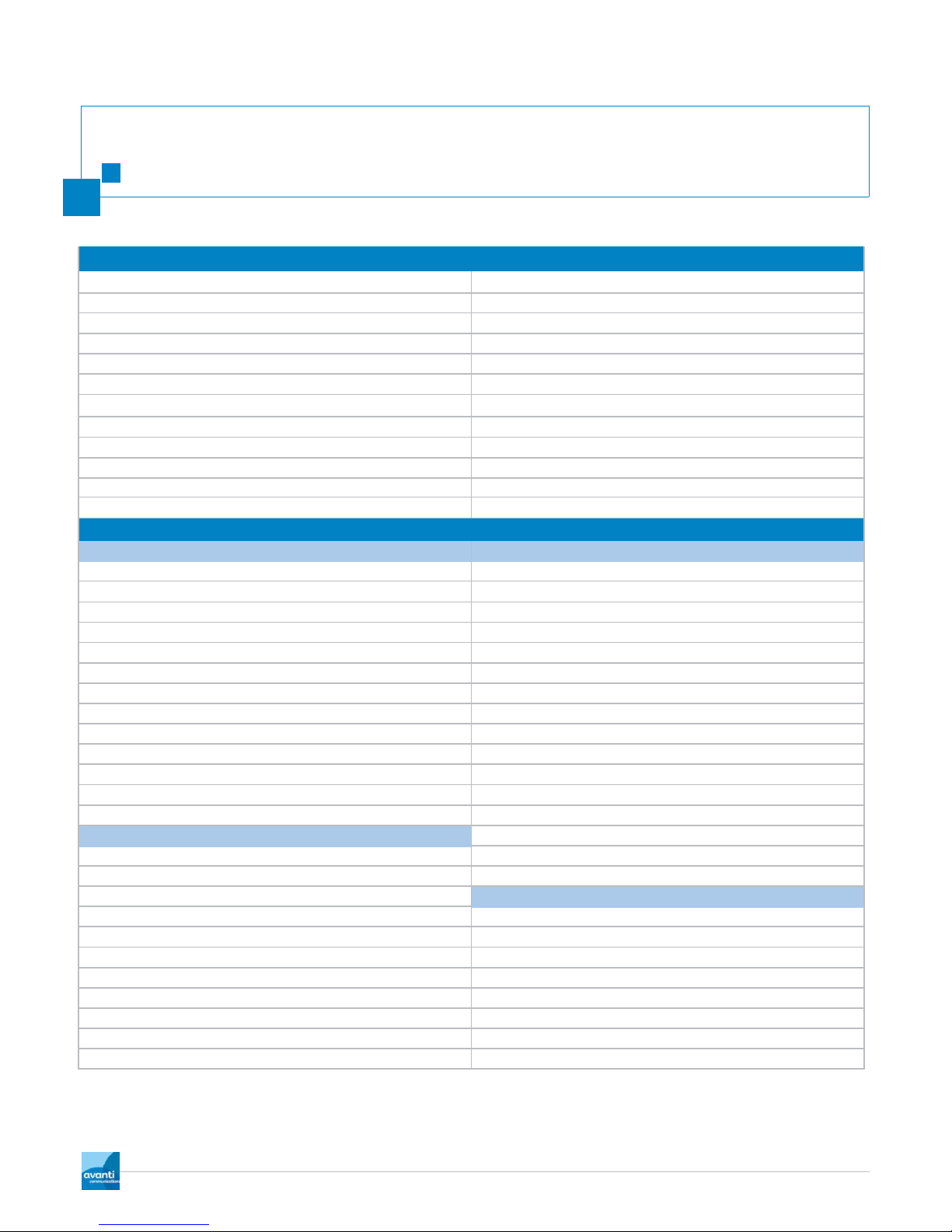
CONSUMABLE REQUIREMENTS
Standard Installation Consumables
NOTE:
Cable ties 300mm black / white /clear. ALL INSTALLATION ENGINEERS SHOULD HAVE
WF100 Cablecon 5.1 compression connector. ACCESS TO THE COMPLETE INSTALLATION
WF125 Cablecon 6.0 compression connector. CONSUMABLES LIST OPPOSITE TO ENSURE
Hi-grade multi use barrel F-F connector. ALL INSTALLATIONS CAN BE COMPLETED ON
Silicon Dielectric grease. THEIR SCHEDULED DATE.
Silicon based self
–
amalgamating tape.
RX and TX labels.
M8-M10 Rawl-bolts.
WD 40 or equivalent.
WF100 Twin-sat CAI approved foam dielectric.
Installation Consumables.
BRACKETS and FIXINGS. CABLE.
Standard
60mm
L
bracket short. 35cm
WF100 Twin-sat CAI approved foam dielectric.
Standard 60mm
L
bracket long. 55cm WF125 green direct burial CAI approved.
K+K
or
A
frame (Both to have support leg) Cat5e external grade 100 meter.
20cm / 8in. Cat5e 2 meter straight patch lead.
46cm / 18in. 4 gang surge protected mains extension.
55cm / 24in. Twin-sat 7 mm Grommet black / white.
60mm / 2meter or 3meter pole. 7 mm grommet black / white.
V
bolts for 60mm pole including washers. 10 mm grommet black / white. (WF125)
Universal Clamp. Cable clips 2 x 7mm masonry grade.
Non penetrating roof mount 60mm. Cable clips 9mm round masonry grade.
4 x 600mm x 600mm x 50mm flags. Cable clips 6-7mm round masonry grade.
M10 / 16mm Rawl-bolts. Pin plugs.
Rapid set postcrete. Brick plate terracotta.
DRILL BITS. Brick plate white.
16mm 200mm masonry External grade clear silicon.
16mm 600mm masonry Cable ties 300mm black / white /clear.
16mm 1000mm masonry CONNECTORS.
5.5mm 100mm masonry WF100 Cablecon 5.1 compression connector.
Grinder cutting disks. WF125 Cablecon 6.0 compression connector.
Hi-grade multi use barrel F-F connector.
Silicon Dielectric grease.
RJ 45 connectors.
Silicon based self
–
amalgamating tape.
Replacement Cable stripper blades.
RX and TX labels.

.9
Avanti Installation Manual
2.0
General
7. HEALTH AND
SAFETY
General health and safety for installing Vsat systems.
For your safety and protection, read this entire installation guide before attempting to install any
Avanti Broadband system. In particular, read this safety section carefully. Keep this safety information
where you can refer to it if necessary.
7.1 PRODUCT WARNING LABELS
The following safety alert labels are affixedto the antenna feed support arms, radio transmitter, and antenna
reflector,
respectively.
POWER
FEED
SUPPORT
ARMS
RADIO TRANSMITTER
These labels advise that the antenna emits radio frequency (RF) energy. Because of this potential safety hazard,
observe all cautions on these labels and in the next section, Antenna installation safety.

.10
Avanti Installation Manual
2.0
General
6. HEALTH AND
SAFETY
WARNING
Only Avanti accredited installers may install or service Hughes antennas and their components installed on Avanti
Hylas networks. Installers must expressly acknowledge the Avanti requirements for Hughes system installations.
All engineers must be trained in safe use of ladders, working at heights, risk assessment and general health and
safety including the correct use of PPE equipment.
7.2 PPE
CAUTION
All engineers shall be trained in the use of personal protection equipment, it is the engineer’s responsibility to
ensure this equipment is used, maintained and replaced as necessary. Appropriate PPE shall be used at all times
for the protection of engineers and 3rd parties, failure to use PPE provided for your safety could result in serious
injury or death.
7.3 SAFE USE OF LADDERS
DANGER
Only engineers with working at heights certification should carry out an install where a ladder if required. A
risk assessment should also be completed prior to any commencement of any work. All work at height should
follow the guidelines set out in the safe use of ladders and working at heights documentation.

.11
Avanti Installation Manual
2.0
General
7. HEALTH AND
SAFETY
7.4 WORKING AT HEIGHTS
DANGER
If an engineer is on a roof, tower, or other high structure or use a ladder or scaffold to access the work site, then
they should follow the following precautions to prevent personal injury or death:
Walk only on sound roof structures
Make sure the antenna assembly and installation surface are structurally sound so that they can support all
loads (equipment weight, ice, and wind)
Use safety equipment (for example, a lifeline, ladder restraint system) appropriate for the work location.
When ladders are require they should always be secured using the appropriate restraint systems following
working at heights guidelines
Follow all manufacturer safety precautions for all safety and other equipment used
Perform as many procedures as possible on the ground
DANGER
To avoid electric shock, stay at least 20 ft from power lines
If any part of the antenna or mount assembly comes in contact with a power line, call the local power
company to remove it. Do not try to remove it yourself
Failure to heed these warnings could result in serious injury or death
WARNING
Do not work in high wind or rain; or if a storm, lightning, or other adverse weather conditions are either
present or approaching
Do not attempt to assemble, move, or mount the antenna on a windy day. Even a slight wind can
unexpectedly create sudden strong forces on the antenna surface
CAUTION
If the antenna or mount assembly begins to fall during the installation, do not attempt to catch it.
Move away and let it fall

.12
Avanti Installation Manual
2.0
General
7. HEALTH AND
SAFETY
WARNING
Antennas that have been improperly installed or attached to an unstable structure are susceptible to
wind damage, which can be very serious or even life threatening.The product owner and installer
assume full responsibility that the installation is structurally sound to support all loads (weight, wind,
and ice) and is properlysealed against leaks
7.5 RADIATION HAZARDS
CAUTION
Observe these precautions to avoid exposure to RF radiation, a potential safety hazard:
The antenna must be installed in a location not readily accessible to children and in a manner that prevents
human exposure to potentially harmful levels of radiation
Antennas mounted at any site with a greater than 30° elevation angle must be installed such that the lower
lip of the antenna reflectoris at least 5 ft above any surface upon which a person might be expected to
stand, and 3 ft 3 inches from any opening (such as a door or window) in a building or adjacent structure
Antennas mounted at any site with a less than 30° elevation must be installed such that the lower lip of
the antenna reflectoris at least 5 ft 9 inches above any surface upon which a person might be expected to
stand, and 3 ft 3 inches from any opening (such as a door or window) in a building or adjacent structure
The antenna must be mounted such that no object that could reasonably be expected to support a person is
within 6 ft 7 inches of the edges of a cylindrical space projecting outward from the antenna reflector toward
the satellite
If the above distance requirements cannot be met, the antenna must be mounted in a controlled area
inaccessible to the general public, such as a fenced enclosure or a roof
A fenced installation must have a locked entry, and the fenced area must be large enough to protect the
general public from exposure to potentially harmful levels of radiation
Access to a roof installation in a commercial, industrial, or institutional environment must be limited by a
door or a permanently fastened ladder that is locked to deny access to the general public.
Once the transmitter becomes operational, maintain a safe distance; at least 3 feet
Failure to observe these cautions could result in injury to eyes or other personal injury

.13
Avanti Installation Manual
2.0
General
7. HEALTH AND
SAFETY
CAUTION
All antennas of any type or size must carry an industry standard and government approved Radiation Hazard
Caution label on the feed support arm
A fenced or roof installation in a commercial, industrial, or institutional environment must carry a Radiation
Hazard Caution sign on the access door, gate, or permanently mounted access ladder within plain sight of
anyone approaching the antenna from the front or sides of the reflector
Failure to observe these cautions could result in injury to eyes or other personal injury
CAUTION
No Satellite antenna over 60cm shall be mounted onto a chimney stack under any circumstance as
this contravenes planning and building regulations
7.6 COSHH
CAUTION
All substances identifiedunder the
con
t
r
o
l
of
substances hazardous
to health shall be
recorded a
n
d
the relevant product data sheets will be issued to all engineers effected. These
substances will be namely: - silicon sealant, silicon grease, wd40 and postcrete
7.7 RISK ASSESSMENT
CAUTION
All engineers shall carry out a full risk assessment prior to commencementof any work; the details obtained
from this activity shall be recorded on a risk assessment form, or submitted electronically via AFA when
available. It is the responsibility of all engineers to ensure that an accurate risk assessment is completed,
submitted and acted on during any installation works. Any risks that are
identified
must be removed or
controlled where this is not possible, your line manager must be contacted immediately for further guidance,
and no work must be carried out until the risk has been removed or sufficientcontrol measures have been put
in place to reduce the identifiedrisk to a satisfactory, controlled level.

.14
Avanti Installation Manual
2.0
General
7. HEALTH AND
SAFETY
7.8 METHOD STATEMENTS
All engineers should complete a full method statement alongside the risk assessment detailed above. This
method statement should detail the installation requirements and the methods that will be used to complete
the installation using the control measures identifiedduring the risk assessment.

.15
Avanti Installation Manual
2.0
General
8. QUALITY ASSURANCE
All installations automatically go through a period of quality monitoring, aswell asthis customer site
are
visited and thoroughlyinspected to
ensure
the guidelines in this document have been
implemented
correctly. All installations will be analysedandreports generated to identify installation related issues.

.16
Avanti Installation Manual
2.0
Site Hardware Preparation
9. SITE
ASSESSMENT
AND
SURVEY
1. Explain the installation process to the customer.
2. Conduct a site survey of the purposed antenna location to confirm the location will have clear line of sight to
HYLAS 1 at 33.5° West or HYLAS 2 at 31.0°East
9.1 ANTENNA LOCATION.
Care must be taken when choosing a location for the antenna, consideration should be given to the
building fabric and it‘s suitability for mounting a large antenna to.
●Suitable mounting locations should be of brick, block, stone or concrete construction.
●Antennas should be mounted well above head height where possible.
●Working at height guidelines should be observed, mounting the antenna at a safe height. No antenna
should be mounted at extreme heights purely for cosmetic reasons, this will be governed by line of sight.
●Be careful not to select a location that will obstruct windows, doorways, walkways or vehicle access routes.
●Line of sight should be checked from the proposedlocation using a inclinometer to ensure a clear view
of the satellite can be obtained.
●When choosing antenna location make sure it is safe to erect a ladder up to the antenna mounting
position, also consider any access required along any cable routes to the entry point.
●Try to minimise cable length, by mounting antenna as close as possible to entry point.
●If there is a choice of antenna location, choose the site that is most aesthetically pleasing, as long as it
does not affect safety during the installation, or Line of Sight.
CAUTION
●Do not mount bracketry on top few course of brick as this is a weak point in wall structure, all
brackets should be a minimum of 50cm from any wall edge.
●Antennas should not be mounted directly onto a timber structure.
●Antennas should not be mounted on any chimney.
●Try to avoid installing the antenna or bracketry below head height to remove risk of people injuring
themselves by walking in to it, and also remove any exposure risk from radiation emissions. If this is
essential make sure it is clearly marked and physically access is restricted by a fence and locked
gate.
●Consideration must be given when installing equipment in situations where it may be struck by
moving vehicles or machinery, especially on farms or industrial properties, check with the customer
as to the types and heights of vehicles that may operate in the area of the antenna.

.17
Avanti Installation Manual
2.0
Site Hardware Preparation
9. SITE
ASSESSMENT
AND
SURVEY
9.2 LINE OF SIGHT
Line of sight is probably the most important aspect of the satellite broadband installation;this will determine
how good a signal can be achieved and therefore the performance of the broadband connection.
CAUTION
Failure to obtain clear line of sight will result in a degraded signal and therefore a poor intermittent
broadband service or no connection and no service at all. It will also affect the commissioning of the terminal
which will ultimately fail.
To ascertain whether a good line of sight is possible the following process should be followed.
Use a net resource i.e. www.dishpointer.comto check pointing details for the postcode you are going to be
installing at, you will require the magnetic azimuth and the elevation for install location before arrival onsite
.
These details can also be obtained by inputting the Gps coordinates into the Hughes terminal, this option will
be discussed later.

Site Hardware Preparation
.18
Avanti Installation Manual
2.0
9. SITE
ASSESSMENT
AND
SURVEY
9.3 USING AN INCLINOMETER
From the antenna installation location use an inclinometer to determine
whether clear line of sight can be obtained. To ascertain this look through the
compass part of the inclinometer with both eyes open and line the required
azimuth coordinate up with the crosshair in the view
finder,
once lined up
make a mental note of the point on the horizon that the crosshair sits.
Turn the inclinometer over to the elevation scale and again look through the
elevation lens and findthe point on the horizon you had previously noted.
Once found tilt the inclinometer upwards until the elevation scale reads the
required number of degrees determined using www.dishpointer.com
.
You now have the exact position of the satellite, you should allow a margin on
this position of ± 3° on the azimuth and
–
3° on the elevation, this will ensure
you have completely clear line of sight to the satellite and there is sufficient
clearance for any tree growth, where fast growing trees are identifiedsuch
as conifers and poplars the elevation allowance should be increased to - 5° to
ensure sufficientclearance is continued in the future.
The position you have now identified in the sky should be clear along with
the allowance areas, if so the installation can go ahead from this antenna
installation location.
CAUTION
If there are any objects, trees, buildings in line of sight, an alternative installation location will need to be found.

Site Hardware Preparation
.19
Avanti Installation Manual
2.0

Site Hardware Preparation
.20
Avanti Installation Manual
2.0
9. SITE
ASSESSMENT
AND
SURVEY
9.4 USING A COMPASS
Compass Needle:
This arrow will always point to the Magnetic North.
This will be outlined later in more detail. Often the
compass needle is painted red so you do not mistake
the north arrow for the south arrow.
Heading
Arrow:
This arrow is fixedon the base plate and it should
point in the direction that you need to look at. So
when you hold a navigation compass, always make
sure this arrow is pointed towards your destination.
I.e. The satellite.
Turntable Housing:
This top part of the Compass holds the basic
directions (north, east, south and west) and the
degrees. As we will see later on, this housing is
turntable so you can adjust your bearing to the
magnetic north.
Base Plate and Grip:
The base plate often has a ruler that can be used in
combination with your topographical map for
determining distances and triangulating your position.
The end is often shaped to form a palm grip with the
HeadingArrow pointing in the direction that you are
going.
This manual suits for next models
4
Table of contents
Other Avanti Antenna manuals
Popular Antenna manuals by other brands

Sirius Satellite Radio
Sirius Satellite Radio PowerConnect XMP3I user guide

M2 Antenna Systems
M2 Antenna Systems 2M7X quick start guide

Maximum
Maximum DA-5100 manual

Magnadyne
Magnadyne RV2458 installation manual

CG Antenna
CG Antenna GW-1000 user manual

Intellian
Intellian i4 Inland Installation and operation user guide

Winegard
Winegard Trav'ler Preinstallation manual

AOR
AOR LA800 instruction manual

Feig Electronic
Feig Electronic ID ISC.ANT800/600 Installation and tuning guide

Cisco
Cisco AIR-ANT2485P-R quick start guide

prodelin
prodelin 3.8M Assembly manual

Infinity
Infinity KP PERFORMANCE ANTENNAS KP-6DCN-4-C5X quick start guide