AVE AF927PLUS User manual

INSTALLER & USER MANUAL FOR CENTRAL UNITS AF927PLUS –AF927PLUSTC
AF927PLUS and AF927PLUSTC
Wireless/Wired central units
with built-in Wi-Fi module
INSTALLATION AND USER MANUAL

2
TABLE OF CONTENTS
AF927PLUS and AF927PLUSTC - INSTALLATION MANUAL.........................................................................................................3
INTRODUCTION .........................................................................................................................................................................3
TECHNICAL FEATURES................................................................................................................................................................4
POWER SUPPLY UNIT............................................................................................................................................................5
Sizing of the system .........................................................................................................................................................6
Protections on the 12-14Vdc power supply and usage limitations .................................................................................6
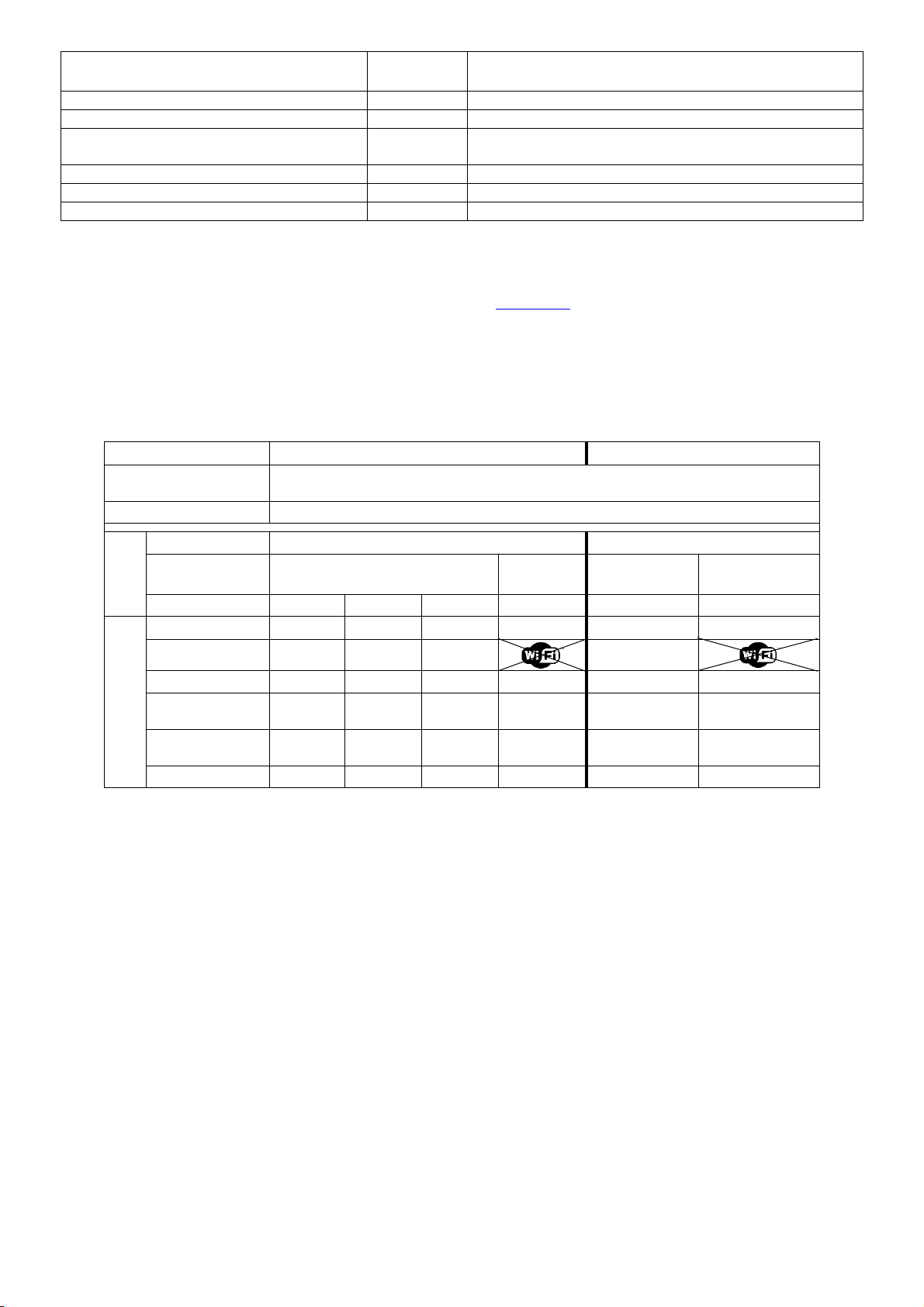
DISPLAY ELEMENTS...............................................................................................................................................................6
INSTALLATION............................................................................................................................................................................7
PRECAUTIONS FOR CORRECT CONTROL UNIT INSTALLATION..............................................................................................7
GENERAL INFORMATION ......................................................................................................................................................7
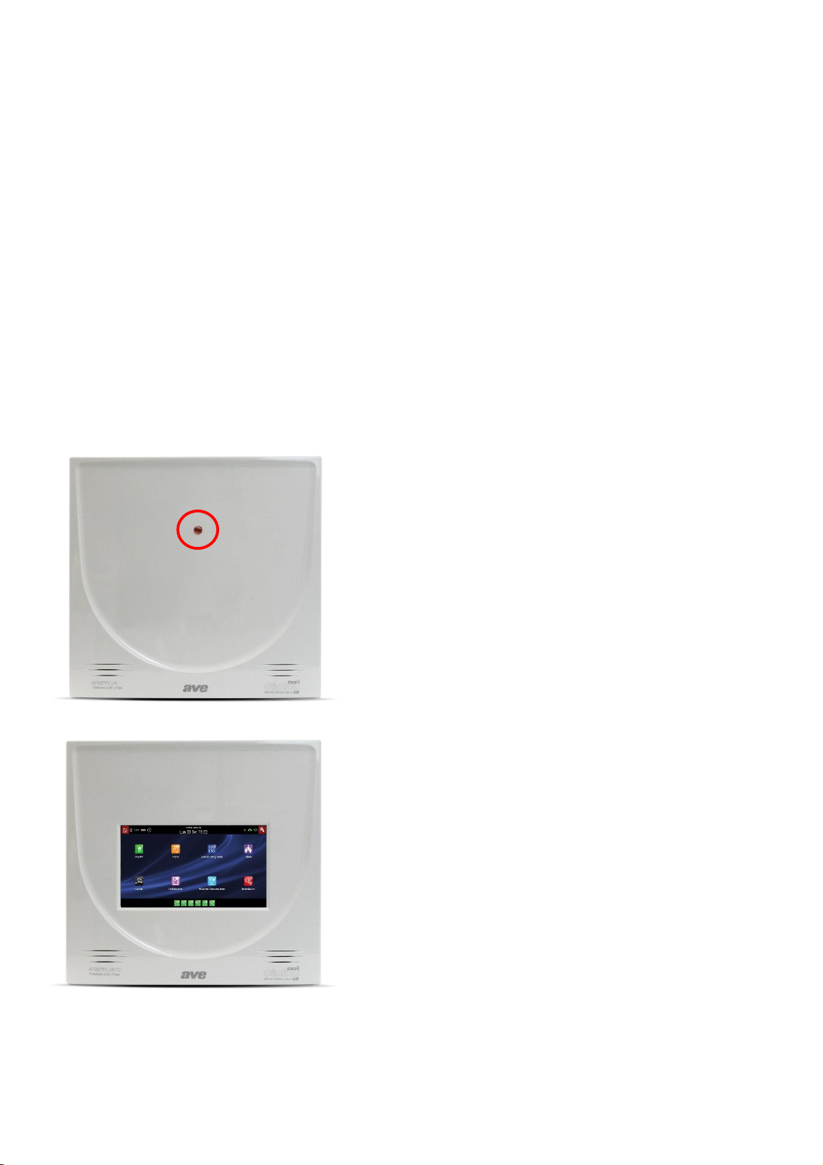
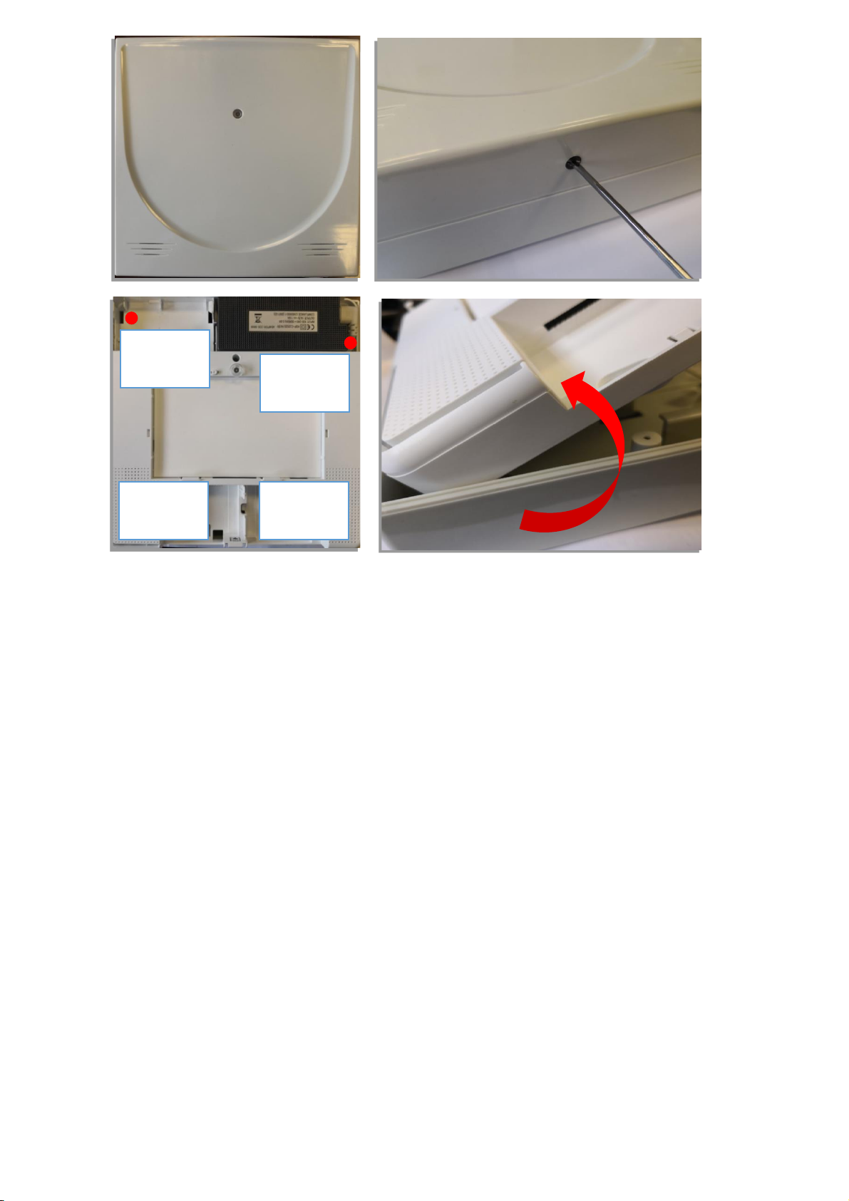
OPENING THE BOX, WALL MOUNTING.................................................................................................................................7
GUARD PREVENTING OPENING AND REMOVAL...................................................................................................................8
SECURITY: SUPERVISION, ANTI-TAMPER, BATTERY CHECK, ANTI-SCANNER. .......................................................................8
PROGRAMMING: PRELIMINARY OPERATIONS AND QUICK START-UP ......................................................................................9
PRELIMINARY OPERATIONS ..................................................................................................................................................9
PRELIMINARY OPERATIONS FOR CONNECTION TO AVECLOUD (RECOMMENDED). ............................................................9
DEFAULT DATA AND QUICK PROGRAMMING FOR AF927PLUS (model without screen) ...................................................10
RAPID PROGRAMMING FOR AF927PLUSTC (model with screen).......................................................................................25
CONTROL UNIT MENU - INSTALLER INSTRUCTIONS ................................................................................................................28
SUMMARY OF HOME PAGE FUNCTIONS ............................................................................................................................28
MEANING OF MULTI-STATUS ICONS ..................................................................................................................................29
Type of user connected to the control unit: ..................................................................................................................29
Cloud status: ..................................................................................................................................................................29
Remote connection status (remote service):.................................................................................................................29
MEANING OF THE OTHER CONTROL UNIT ICONS...............................................................................................................30
System activation................................................................................................................................................................30
Control Unit Events Memory ..............................................................................................................................................30
Scenarios Management and Time Programmer .................................................................................................................30
User Management ..............................................................................................................................................................30
View Cameras .....................................................................................................................................................................30
Test functions .....................................................................................................................................................................30
Communication parameters...............................................................................................................................................30
Settings ...............................................................................................................................................................................30
Devices and Areas...............................................................................................................................................................32
INTRUSION DETECTOR PARAMETERS .......................................................................................................................37
Parameters common to all devices ......................................................................................................................37
AF963R-DB (PIR) –AF965R-DB: Double PIR curtain-effect detector - additional parameters .............................38
AF964R-DB: outdoor double PIR radio detector + microwave technology - additional parameters ...................39
AF976R-DB: outdoor double PIR radio detector, long range curtain effect - additional parameters..................39
AFTR02: universal transmitter for technical alarms .............................................................................................39
AF53903R-DB: radio siren.....................................................................................................................................40
AFTRA03: signal repeater .....................................................................................................................................40
RADIO KEYPAD PARAMETERS....................................................................................................................................40
BYPASSING DEVICES.......................................................................................................................................................41
VOICE MESSAGES...........................................................................................................................................................42
GENERAL SETTINGS.............................................................................................................................................................44
Scenario management..........................................................................................................................................45
General control unit parameters..........................................................................................................................47
System information ..............................................................................................................................................49
Utilities .................................................................................................................................................................50
Programming summary ........................................................................................................................................53
REMOTE SERVICE................................................................................................................................................................53
EVENTS................................................................................................................................................................................54
SYSTEM TEST.......................................................................................................................................................................55
Field meter - Radio range .....................................................................................................................................56
Radio range - preventive check ............................................................................................................................56
Device test............................................................................................................................................................56

3
Dialler tests...........................................................................................................................................................57
Siren test...............................................................................................................................................................58
Image test.............................................................................................................................................................58
Relay test..............................................................................................................................................................58
Monitoring............................................................................................................................................................59
Wired inputs.........................................................................................................................................................60
COMMUNICATION PARAMETERS..............................................................................................................................62
Choose connection type.......................................................................................................................................62
Mail.......................................................................................................................................................................65
AVE Cloud .............................................................................................................................................................66
Other communication parameters and interfacing with AVE home automation system....................................66
USERS ........................................................................................................................................................................68
CODE RECOVERY PROCEDURE ............................................................................................................................................70
WIRED BOARD .........................................................................................................................................................................70
DESCRIPTION OF TERMINAL BLOCK.........................................................................................................................................71
CONFIGURATION OF INTERNAL WIRED BOARD ......................................................................................................................72
Input configuration...............................................................................................................................................73
NC DOUBLE...........................................................................................................................................................74
Output configuration............................................................................................................................................75
WIRING DIAGRAM FOR WIRED INPUTS ...................................................................................................................................76
INPUT CONNECTION TYPES FOR CORRECT BALANCING ...........................................................................................76
EXAMPLE OF CONNECTION.......................................................................................................................................77
GSM TELEPHONE DIALLER MODULES - art. AFGSM04, GSM 4G - art. AFGSM04-4G ..............................................................78
FAQ .....................................................................................................................................................................................81
APPENDIX ............................................................................................................................................................................83
AF927PLUS and AF927PLUSTC - AVE Firmware Settings .........................................................................................................83
AF927PLUS and AF927PLUSTC - INSTALLATION MANUAL
INTRODUCTION
AF927PLUS is a wireless / wired central unit with built-in Wi-Fi module. It can manage up to 99 detectors individually
identifiable through the "label" function which, when properly programmed, shows the point of origin of the alarm on
the display (eg: living room, kitchen, corridor, etc.). Thanks to a vocal synthesis provided on board, the label can also
be of the vocal type. This makes it possible to identify the individual detector by means of a programmable voice
message. The vocal synthesis also allows the recording of voice messages that inform the user about the main
events that have occurred on the system (eg. door open; system armed; system disarmed; etc.). The wired board
allows you to manage n.8 inputs with free balancing and n.16 with NC balancing. A wired output can also be controlled
by time, thanks to an internal timer, to manage the load by time slots.

4
TECHNICAL FEATURES
Note: the following is valid for both AF927PLUS and AF927PLUSTC models, unless otherwise specified. The
difference between the two central units is only relative to the presence of a 7” LCD screen on the AF927PLUSTC
central unit which has been replaced by a LED on the AF927PLUS central unit.
•Main power
o230Vca -15%+10% - 50/60Hz
•Secondary power source: To be completed with 2 batteries 12V/1,8 Ah - reference AF911
oMaximum charging time: 3h
oSignal for low battery at 10,9V and charged battery at 11,4V
•Central unit features:
oTransmission/Reception RF 433MHz/868MHz GFSK Dual band, UE- standard 300-220-1; 300-330;
300-440, wireless range in free air without interference 100m. The wireless range can undergo a
significant reduction in indoor spaces also due to the position of the devices (detectors, sirens, etc.)
in relation to the structure of the premises.
oWireless Inputs:
- n.99 wireless channel –n.99 detectors individually identifiable with a text label via LCD
display or voice label, individually delayed with AND function.
oWired Inputs:
- n.8 wired inputs with double balancing
- n.1 double balanced input for wired electro-mechanical activator with at least 300
combinations.
oRadio outputs:
- coded 72-bit digital transmission for “alarm” - “total activation” - “partial activation” -
“deactivation” + 16 coded commands that can be managed
oWired outputs:
- n.1 for indoor siren control
- n.1 for outdoor self-powered siren
- n.2 programmable relays for various free exchange functions (max 500 mA@12V).
on.6 activation areas (1,2,3,4,5,6).
oRadio tamper detection: reception of tamper signal from each individual detector - reception of “alive”
signals transmitted every 28 minutes and of low battery signal (SUPERVISION) if necessary.
oR.F. anomalies: continuous, simultaneous and programmable control of the 2 operating frequencies.
oPossibility to store n.32 AF943R remote controls, individually identifiable with a text label via LCD
display or voice label.
oMemory of last 500 events (non-volatile memory).
oEvent messages. Voice messages can be recorded to inform the user in real time of the main control
unit events (control unit on; control unit off; door open; outdoor detector alarm; pre-alarm; tampering;
new event)
oTiming: activation delay, programmable from 1 to 99 seconds - input delay, programmable on each
detector, from 1 to 45 seconds - general alarm time, 3 minutes fixed - programmable 24h clock
oDisplays: 2x16-character display, with the ability to identify each individual peripheral
oIndoor siren: 106dB alarm siren
oAcoustic signals: voice messages to guide installation and user communications + low intensity
buzzer.
oBuilt-in Wi-Fi module
oDIMENSIONS: 307x200x53mm
oWEIGHT:
- AF927PLUSTC 2.0 Kg
- AF927PLUS 1.5 Kg
oTEMPERATURE: operating/storage: -25°+55°C –Humidity 95%.
•Characteristics of dialler AFGSM04, AFGSM04-4G:
AFGSM04: GSM/GPRS module for AF927PLUS and AF927PLUSTC control units with antenna. This
device enables the control unit to perform all telephone activities over the mobile network, i.e. caller ID,
two-way voice, SMS, MMS, digital transmissions with SIA protocol, e-mail transmissions.
AFGSM04-4G: in addition to those described for control unit AFGSM04, the AFGSM04-4G enables
remote control unit management via the AVE Cloud service.
VIA SMS MESSAGES FUNCTIONS
It is possible to control the control unit with SMS messages. These commands are subject to the timing
allowed by the SIM manager, so they may not be received immediately.
Attention! ַ ײ = space

5
Command / control from the central unit
Operazione
SMS to
send
Answer from the plant
check the ON-OFF status of the plant
C?
ON ײַOK ACF(zone) ײַOK OFF ײַOK
total arming of the control panel
ON
ON ײַOK
partial arming of zones
ON ײַ
ACF(zone)
ON ײַACF(zone) ײַOK
disarming of the control panel
OFF
OFF ײַOK
reading of the events memory
MEM?
last 3 events as indicated in the historical memory
request for the remaining SIM credit
?
answer € according to the SIM manager's modalities
EC Declaration of Conformity:
The manufacturer AVE SPA declares that the radio-based intrusion detection control unit, code AF927PLUSTC and
AF927PLUS and related GSM module AFGSM04, comply with Directive 2014/53/EU.
The full text of the EU declaration of conformity is available at: www.ave.it.
POWER SUPPLY UNIT
The internal power supply unit supplies a nominal voltage of 14.5Vdc (@100-240V –50/60Hz) and a current of 1.6A;
to facilitate calculation of total absorption and thus autonomy in the case of mains power outages, the following table
is provided:
Code
AF927PLUSTC
AF927PLUS
Features of the power
supply unit
14.5V –1.6A (@100-240V –50/60Hz)
Rechargeable batteries
2x12V –2.2Ah
Code
AF927PLUSTC
AF927PLUS
Power supply
condition
230 V OK
Black OUT
230 V OK
Black OUT
LCD brightness
100%
50%
10%
0%
n/a
n/a
Current
consumption in
stand-by
Control unit
390
300
200
30
150
20
Wi-Fi module
40
40
40
40
Wired board
20
20
20
20
20
20
2G GSM module
(AFGSM04)
10
10
10
10
10
10
GSM 4G module
(AFGSM04-4G)
45-80
45-80
45-80
45-80
45-80
45-80
Total
460 (530)
370 (440)
270 (340)
60 (140)
220 (290)
50 (120)
Unless otherwise indicated, the values are given in mA.
In brackets the maximum absorption value with telephone dialler art. AFGSM04-4G.
Note:
•In the event of a power failure, the control unit automatically switches the Wi-Fi module off to save energy.
However, a special parameter is available so both Wi-Fi module and 4G GSM module can be kept active
simultaneously (see chapter GSM programming).
•To guarantee 24-hour system autonomy in the event of a power failure, it is not advisable to exceed a
maximum absorption value of 180mA (with two 12V 2.2Ah batteries).
•When using wired devices, a consumption of 120mA should not be exceeded. Should it be necessary to
connect a larger number of devices, an additional power supply unit with back-up battery must be used and
the fault signal for this power supply reported to the control unit or a wired bus input board (art. AFEX6I-
REN).

6
Sizing of the system
When using the control units, the installer must pay utmost attention to sizing of the system, with an eye power
consumption and resulting autonomy. EN 50131 sets the minimum power failure autonomy for Grade 2 at 12 hours:
this must be guaranteed (see table above).
How the system is used involves aspects that affect consumption, in particular the brightness of the display,
absorption of any sirens self-powered via cable and of any 12V peripherals connected via cable. These factors must
be properly considered in relation to the rating of the power supply unit which must, in turn, be able to ensure that
connected batteries are properly charged. The table shows the absorption of the 2 control unit models and any related
batteries: for each system the following must be calculated:
•Maximum absorption: this is done by adding the consumption of any other equipment cabled to the control
unit; this must never exceed the capacity of the power supply (it is advisable to keep absorption to 80% of
nominal capacity)
•Minimum autonomy in the absence of 230V power supply, considering the current available from the battery
at 80%.
Protections on the 12-14Vdc power supply and usage limitations
a) Max current limit: 200mA to charge internal battery/batteries (EN 50131-1: the maximum 72-hour charging is
met)
b) Current limit, achieved with resettable polyswitch: 650mA to recharge the battery of any wired siren (art.
AF53900N)
c) Limit for current designated to supply wired peripherals, achieved with resettable polyswitch: this must not
exceed 200mA if the control unit has 2 batteries, 80mA if it has only one battery.
DISPLAY ELEMENTS
•AF927PLUS: multifunction LED.
Green, on steady = control unit off
Green, flashing: control unit off and not powered from mains
Green, flashing 10 seconds upon deactivation: new event
(see event history memory)
Orange, on steady: Initial powering up / Upgrade in progress
/ Maintenance
Orange. flashing: under maintenance and not powered from
mains
Red, on steady: control unit on (flashes for the time it takes to
exit)
Red, flashing: control unit on and not powered from mains
(continues flashing after the time required to exit)
•AF927PLUSTC: 7”colour touch screen LCD display.
Multifunctional colour touch screen,
LCD Dimensions: 7”
Screen saver function with date and time

7
INSTALLATION
PRECAUTIONS FOR CORRECT CONTROL UNIT INSTALLATION
These devices may only be used in the context of an alarm system and only as described in this manual.
They must be installed on site solely by technicians specialized in “electronic security”. Except for the accessible
compartments, opening the units immediately voids the industrial warranty. Any other use is considered improper
and prohibited. The manufacturer cannot be held liable for any damages resulting from misuse of the product; that
is for any use other than that indicated in this manual.
All control units operate by transmitting and receiving radio signals that are compliant with current standards:
therefore, they must be wall-mounted using the supplied screws and plugs and under conditions that allow for good
propagation of such signals. For this reason, niches and/or columns and/or walls of reinforced concrete should be
avoided, as should installation inside metal cabinets. Extensive metal surfaces and metal grates near the control unit
must also be avoided, even if embedded in walls. Positioning must take into account the mandatory position of the
detectors and sirens, making certain that the control unit is “central” to these units.
The quality of the signal received by control unit can be checked and, when in doubt, this check should be performed
before securing the control unit to the wall: when working with radio devices of this type, always remember that
moving just a few tens of centimetres can often significantly improve signal transmission/reception.
It is best for the control unit to be hidden from view but, at the same time, installed in a convenient position where all
its functions, including voice information, can be used. Useful sites are: behind doors, inside wooden or plastic
cabinets, behind pictures and/or pieces of furniture. It is advisable to avoid installation near other electronic devices.
Once the position has been defined, the connection wires that are to enter the back of the device —possibly by
breaking through the entry spaces arranged on the container —must be brought together. In particular, the cable
carrying power from the mains must be disconnected upstream during installation.
GENERAL INFORMATION
These devices are the heart and brains of a modern alarm system: equipped with the appropriate peripherals
(detectors, sirens, etc.), they manage the burglary/aggression intrusion detectors, both wireless and wired, all types
of wireless “technical” alarm sensors (water, smoke, gas, temperature, etc.), self-powered Wi-Fi cameras, remote
actuation devices.
Depending on the models and accessories included in the system, the control units can trigger high-powered acoustic
alarms and/or local warning messages through the appropriate wired and wireless sirens. They also activate landline
and mobile telephone calls, SMS messages, digital calls to surveillance centres. All operating functions can be
managed remotely via smartphone, tablet, web page and through the free AVE Cloud application (from
activation/deactivation to requesting of control frames and “push” signalling of new events).
The control units operate connected to the power mains and have a power supply able to keep the rechargeable lead
batteries optimally charged; these batteries are located in a space at the bottom of the box, together with the cabled
portion of the devices, thus enabling convenient wiring. Protection against opening/removal is guaranteed by special
break-in sensitive elements. The various functions are always shown in clear text on the display of the device or that
of the connected remote devices and are protected by a specific installer and user access codes (PIN).
OPENING THE BOX, WALL MOUNTING
Control unit boxes are opened by unscrewing the single screw on the bottom and removing the cover. On the inside,
there are 4 more screws that, with a hinged, “book-like” structure (located to the left of the casing) provide access to
the compartment containing the wired board and batteries.
The cables are routed through the pre-formed compartments at the bottom of the boxes. All electrical connections
must be made in a workmanlike manner, in compliance with the standards and using cables of suitable section.
Secureַtheַdevice’sַremovalַprotectionַmagnet on the back before securing the control unit to the wall using
the provided template.
The control unit must be secured to a wall, at a suitable height, using the screws and plugs provided.

8
GUARD PREVENTING OPENING AND REMOVAL
The opening signal is guaranteed by spring-loaded buttons, the removal prevention signal by a magnet that must be
secured to the wall/support that will hold the control unit using a special template.
CONNECTION TO THE 230Vac POWER SUPPLY
Carefully follow the precautions given below:
oUse flexible cable with conductor having a cross-section of at least 0.75mm2
oThe cable connection terminal is located in the centre of the battery compartment.
oSecure the cable well by tightening the screw of the cable block, after having connected it to the terminals.
The control units do not require earthing.
oAlways disconnect the mains power supply before working on the control unit: always connect the device to
the power mains using a 16A C curve Circuit Breaker.
SECURITY: SUPERVISION, ANTI-TAMPER, BATTERY CHECK, ANTI-SCANNER.
The various system devices communicate with one another via two-way radio communication in which each signal
is followed by confirmation: this enables the supervision of all wireless devices, with warning in case of failure, and
control of battery charge, with signalling when replacement is needed. In addition, in each device, the anti-tamper
controls are always active so that any attempt to open the casings and/or detach the unit from its housing are
immediately reported and cause an alarm, even when the system is disconnected. For this reason, the control unit
must be set in TEST mode before the batteries are replaced. The control unit checks whether there is any radio
interference that could prevent system function and signals this when needed. Network connection: the control unit
accommodates all security systems that must be properly enabled to prevent unauthorized access.
Warning! The manufacturer declines all responsibility for any unauthorized access that may occur.
Screw
#1
Screw
#2
Screw
#4
Screw
#3

9
PROGRAMMING: PRELIMINARY OPERATIONS AND QUICK START-UP
PRELIMINARY OPERATIONS
•With the control unit completely switched off, if applicable, insert the AFGSM04, AFGSM04-4G, AFGSM04-
AE modules with its SIM card (note: deactivate the SIM card PIN before inserting it);
•Connect the control unit to the power supply and start it up;
•Connect the back-up batteries (code AF911).
Note: for AF927PLUS (version without LCD touch screen), make certain that a charged AF911 battery is
available at the installation site.
•Prepare a tablet or a PC to be connected to the control unit. This is not necessary for the model with screen
(code AF927PLUSTC).
PRELIMINARY OPERATIONS FOR CONNECTION TO AVECLOUD (RECOMMENDED).
•Download the AVE Cloud app from the APP Store or Google Play.
•Access the AVE Cloud site: https://avecloud.ave.it/
•Create a new user and request credentials for a new system to be supervised.
•Make note of the credentials for the selected system (the system sends an email confirming the new system
request and indicating the credentials selected during activation).
Note: to connect the system to the “AVE Cloud” remoting system, the control unit must be connected to the home
Wi-Fi network and it must have an Internet connection. Without an Internet connection, the control unit cannot be
remoted.
Compartment for SIM
card
Compartment for
GSM module
If the GSM module
needs to be removed:
using a pointed object,
press on the hook
locking the module.

10
DEFAULT DATA AND QUICK PROGRAMMING FOR AF927PLUS (model without screen)
Note: for version AF927PLUSTC with screen, skip to page 26.
The control unit has a Wi-Fi module that can be accessed from any device with a WEB browser. The main data
required to connect to the control unit are given below:
a) At initial start-up, the control unit is in ACCESS POINT mode: it generates a Wi-Fi network whose SSID is
encoded with the name AF927_XXXXX, for example: AF927_C6HAB;
b) IP address: 192.168.100.1;
c) No password is required to access the AF927_XXXXX network;
d) The first screen proposed by the system is the control unit start-up screen.
Meaning of the various terms used on the system access page:
•UPD: version of the software package including the control unit
•SOM: version of the control unit SOM (System ON Module) firmware
•WEB: version of the firmware for the WEB graphical interface
•CARRIER: software version for the low-level firmware module
•IMEI: IMEI (International Mobile Equipment Identity) number of the previously connected AFGSM04
module (if any). If the module is not present, the message “NO GSM” will appear.

11
e) Press the “START” screen to call up the programming WIZARD: the column on the left is used to scroll
through the various system programming menus. Pressing any one of them (e.g.: language/country) causes
the box to turn grey and the page used to set the parameters of each function appears in the box on the
right.
The operations that must be performed to program the main settings and system peripherals (for advanced settings
and/or specific details related to the various functions, check the specific system sections) are indicated below:
1. Set language and country
2. Set at least one user code; entering the code for the POWER USER (MASTER USER) is mandatory and
is performed as follows:
a. Click on the Users menu:
b. Click on the symbol for the POWER USER (MASTER USER) and set the PIN (5- or 6-digit)
and the other user parameters:
Scroll section to
choose the various
settings
Indication of the setting
selected
Parameters setting section

12
The meanings of the various parameters are given below:
▪Total activation (cannot be edited by the Power User): enables activation of all system
areas;
▪Total deactivation (cannot be edited by the Power User): enables deactivation of all system
areas;
▪Partial activation: calls up a quick partial activation (future setting –not currently
implemented);
▪User enabled (cannot be edited by the Power User): makes it possible to disable the user
and relative system privileges;
▪PIN: enter a 5- or 6-digit user code.
Note: the user code cannot be the same as the installer code and the code “000000”
cannot be used;
▪Phone: user's telephone number;
▪Enable direct access to control unit: to enable the user to manage the control unit
remotely via SMS sent from his/her cell telephone;
▪SMS notifications: select the SMS messages to be sent to the user in response to intrusion
detection system events.
Note: the send notifications via GSM function is active and can only be set if on the control
unit has a GSM module installed (code AGSM04);
▪Voice message notifications: select the voice messages to be sent to the user in response
to intrusion detection system events.
Note: the send notifications via GSM function is active and can only be set if on the control
unit has a GSM module installed (code AGSM04);
▪Enable e-mail: enables sending the user an e-mail in response to intrusion detection system
events;
▪E-mail: user's e-mail address;
c. Confirm by pressing OK.

13
1. Set Installer Code
The installer identification code must be entered as follows:
a) Enter:
▪Name: name of the installer;
▪CURRENT PIN: 5 or 6-digit installer code;
Note: the installer PIN cannot be the same as the user PIN and cannot be “000000”;
▪Phone: installer's telephone phone number;
▪E-mail: installer's e-mail address;
b) Confirm by pressing OK.
NOTES regarding USER code and INSTALLER code:
It is only possible to exiting the programming wizard (by pressing the home key ) after both the user code
and installer code have been set.
If one of the two codes has not been set, it is not possible to exit the programming Wizard and the following
Pop-Up warning appears:
Note: if the user and installer codes are lost, after rebooting the control unit (disconnect the mains power supply
and battery, wait 1 minute and then reconnect everything), it is possible to enter both menus (user and installer)
using the temporary code 00000 (five zeros; this code is valid for about 3 minutes from moment the control unit
is powered up).
WARNING: the first operation to be performed is to call up the control unit activation/deactivation menu and run
complete control unit deactivation (ex. deactivation of all the areas) using code 00000 to accept any anomalies
present on the control unit. If this is not done, it will not be possible to enter any of the other menus.

14
2. Set System Name
a. This operation is required to identify the
system and to distinguish it from other
systems if the same supervision
account (via AVE CLOUD and related
APP) is used for several systems.
b. Confirm by pressing OK.
3. Set Name of the various areas used to group together the detectors installed on the system:
a. Enter the field for the area to be edited
and enter in its name. Repeat this for
all necessary areas.
b. Confirm by pressing OK.
4. Program the devices that
will be installed on the
system:
a. Select the “Program
your devices” function.
This calls up the screen
shown to the side:
This screen summarises all control unit devices with
the following details:
•Device name
•Type of device (e.g. internal wired
expansion, magnetic contact)
•Node: device no. to interface with the home
automation system
•Device areas: device area
Note
: by default, only the wired board is present. To
activate the wired inputs and related parameters, click
on the eye icon for the internal wired board and
activate the wired inputs required for the system.

15
The buttons at the bottom of the screen have the following meanings:
•“Filter by type of device”: displays only devices of the given type;
•“Filter by areas”: displays only the devices present for the given area;
•“Add other devices”: makes it possible to add more radio devices.
b. To add further devices, press “Add other devices”. This calls up the following screen.
Click:
•“Add devices via radio” to acquire devices via radio (detectors, remote controls, sirens,
etc.).
•“Add BUS devices" to acquire the input/output boards connected downstream of the
AF927INTFIL board (wired BUS generation card) using either the manual procedure (using
the cable supplied with the wired BUS interface board) or automatic procedure.
•“Camera IP” to acquire the IP for the cameras that can be polled via HTTP using JPEG
polling (HTTP snapshot) - For compatibility and other info, log onto
https://www.ispyconnect.com/sources.aspx
and/or see the list of products tested by the AVE INTEAM service.
c. If you wish to acquire a new intrusion detection device (detectors, remote controls, sirens), click on “Add
devices via radio”, the control unit enters listening mode while awaiting the association request message
from a peripheral radio device.

16
To acquire peripheral devices, proceed as follows:
Code
Description
Acquisition mode
Actions to be completed for
acquisition
AF943R
Remote control
Press RED+GREEN
Enter name and configure keys
AF915R-DB
AD915R-MDB
AF963R-DB
AF964R-DB
AF965R-DB
AF976R-DB
Detectors
Insert battery
Enter name, match areas
AF53903R-DB
Siren
Insert battery
Enter name, match areas
AFTR02
Interface for
technical
alarms
Insert battery
Enter name
AFINTFIL
Interface for
wired bus
Plug into control unit
Match areas
AFTR03
Signal repeater
Plug into a mains power
outlet (230Vac)
Enter name, match areas
AF340-T
Tag
Bring the tag at the bottom
left-hand side of the control
unit close to the microphone
Enter name, match areas (by default, all
are matched)
AF970R-DB
Keypad
Insert battery
Enter name, match areas
NOTE: after the correct device save
procedure has been run, the control
unit emits a confirmation sound
(BEEP) and displays the image of the
device saved (see example of
magnetic contact AF915R-DB).
The device acquisition procedure
involves finalising the operation
byַpressingַ “OK”ַwithinַ noַmoreַ
than 10 seconds.
Waiting longer makes it necessary
to repeat acquisition.
•Enter name of the device, match desired areas and confirm.
•Repeat the procedure for
all devices

17
d. To acquire a new intrusion detection device connected to the wired bus generated by the
AF927INTFIL interface
board, click on “Addַ
wiredַ BUSַ devices”;
this calls up the
following screen:
To enable the control unit to associate the input/output boards connected to the wired bus, just select
the manual or automatic device association procedure.
•Press “Automatic device association” and the control unit will start scanning the wired Bus
to acquire the connected boards. Repeat the scanning procedure until all connected boards
are recognised.
•If “Manual device association” is selected, the programming cable supplied with the wired
interface board must be connected to the appropriate connector for the AF927INTFIL board.
The control unit enters “listening” mode while waiting connection of a board:
After hooking up the connection cable, connect one board at a time until the all modules
have been connected.

18
5. Voice messages:
The control unit has voice messages for differentiated, type-specific alerts: EVENTS, AREAS, SYSTEM,
DEVICES.
The control unit software contains pre-recorded messages for the main system events:
•EVENTS:
oAlarm = “Intrusion Alarm”
oTamper = “Tampering in progress”
oBattery dead = “Battery dead”
oAggression rescue = “Robbery in progress”
•AREAS:
oAREA 1 = “Perimeter detectors area”
oAREA 2 = “Volumetric detectors area”
Messages are automatically available in the language selected for the control unit.
Selecting “Record voice messages” lets select the category of messages to be edited.

19
If, for example, you wish to change the alarm message:
a. Click on the “Events” icon to call up the following screen:
b. Edit the necessary voice messages:
•The speaker icon has two states:
voice message recorded
voice message not recorded
•Click on the “trash” icon to delete the voice message
•Clicking on the message name icon makes it possible to record/edit the voice
message. This calls up the following screen.
The meanings of the icons present in the Pop-Up are given below:
= start recording key
= start playback key
= stop playback or recording key

20
•When finished, confirm by pressing OK.
6. Communication parameters
This function is used to define the control unit connection parameters.
The 4 icons make it possible to:
Choose whether to use the control unit in ACCESS
POINT mode or make the control unit a CLIENT of a
master router that enables Internet connection.
Specify the e-mail parameters for the account that
will be used as control unit sender
Set the parameters for connection to AVE CLOUD
Set the advanced communication functions, including
digital surveillance protocols (ADM, SIA, etc.)
This manual suits for next models
1
Table of contents
Other AVE Control Unit manuals
Popular Control Unit manuals by other brands

SIGMA TEK
SIGMA TEK SCP 111-S instruction manual

piezosystemjena
piezosystemjena d-Drive pro instruction manual

CAME
CAME MARTINI 001YE0143 manual

Muller Elektronik
Muller Elektronik S-Box Installation and operating instructions

BS&B
BS&B NACIONAL 3-5111 Instruction and maintenance manual

Nova
Nova SWISS NV Series General operating instructions