AVEKO Evolution VL-3E-1 Owner's manual
Pilot Operating Handbook
for aeroplane VL-3E-1
Registration number :
Serial number : VL-3-
Date :

VL-3E-1 Pilot Operating Handbook
date of issue:
2/40
0. Table of Contents
0. Table of Contents.......................................................................................................................................... 2
1. General........................................................................................................................................................... 5
1.1 Introduction ............................................................................................................................................. 5
1.2 Warnings, cautions and notes ............................................................................................................... 5
1.3 Descriptive data....................................................................................................................................... 6
1.3.1 Aeroplane description................................................................................................................... 6
1.3.2 Basic Technical data ...................................................................................................................... 7
1.4 Two-view drawing.................................................................................................................................. 8
2. Limitations..................................................................................................................................................... 9
2.1 Introduction ............................................................................................................................................. 9
2.2 Airspeed limits ........................................................................................................................................ 9
2.3 Airspeed indicator markings................................................................................................................. 9
2.4 Powerplant............................................................................................................................................. 10
2.5 Engine instrument markings ............................................................................................................... 11
2.6 Miscellaneous instrument marking .................................................................................................... 11
2.7 Weight .................................................................................................................................................... 12
2.8 Centre of gravity ................................................................................................................................... 12
2.9 Approved manoeuvres......................................................................................................................... 12
2.10 Manoeuvring load factors.................................................................................................................... 12
2.11 Crew........................................................................................................................................................ 13
2.12 Kinds of operation ................................................................................................................................ 13
2.13 Fuel.......................................................................................................................................................... 13
2.14 Other limitations ................................................................................................................................... 13
2.15 Limitation placards ............................................................................................................................... 14
3. Emergency procedures .............................................................................................................................. 15
3.1 Introduction ........................................................................................................................................... 15
3.2 Engine failure......................................................................................................................................... 15
3.2.1 Engine failure during take-off run ............................................................................................ 15
3.2.2 Engine failure immediately after take-off ................................................................................ 15
3.2.3 Engine failure in flight (Forced landing) .................................................................................. 15
3.2.4 In-flight engine start.................................................................................................................... 15
3.3 Smoke and fire....................................................................................................................................... 16
3.3.1 Fire on ground ............................................................................................................................. 16
3.3.2 Fire during take-off ..................................................................................................................... 16
3.3.3 Fire in flight .................................................................................................................................. 16
3.4 Glide........................................................................................................................................................ 16
3.5 Landing emergencies............................................................................................................................ 17
3.5.1 Emergency landing ..................................................................................................................... 17
3.5.2 Precautionary landing................................................................................................................. 17
3.5.3 Landing with a flat tire ............................................................................................................... 17
3.5.4 Landing with a defective landing gear..................................................................................... 17
3.5.5 Landing with landing gear in retracted position .................................................................... 18
3.5.6 Landing gear emergency extension .......................................................................................... 18
3.6 Recovery from unintentional spin ...................................................................................................... 19
3.7 Other emergencies ................................................................................................................................ 19
3.7.1 Vibration ....................................................................................................................................... 19
3.7.2 Carburettor icing ......................................................................................................................... 19
3.7.3 Alternator or power supply failure........................................................................................... 19
3.7.4 Cabin opening in flight ............................................................................................................... 19
3.7.5 Tranceiver communication failure ............................................................................................ 20

VL-3E-1 Pilot Operating Handbook
date of issue:
3/40
4. Normal procedures .................................................................................................................................... 21
4.1 Introduction ........................................................................................................................................... 21
4.2 Pre-flight inspection.............................................................................................................................. 21
4.3 Normal procedures............................................................................................................................... 23
4.3.1 Before entering cockpit ............................................................................................................... 23
4.3.2 After entering cockpit ................................................................................................................. 23
4.3.3 Before engine starting and starting of engine.......................................................................... 23
4.3.4 Engine warm up, engine check.................................................................................................. 24
4.3.5 Taxying ......................................................................................................................................... 24
4.3.6 Before take-off.............................................................................................................................. 24
4.3.7 Climb ............................................................................................................................................. 25
4.3.8 Retraction and extension of the landing gear .......................................................................... 25
4.3.9 Cruise ............................................................................................................................................ 26
4.3.10 Descent.......................................................................................................................................... 26
4.3.11 Check before landing .................................................................................................................. 26
4.3.12 On base leg ................................................................................................................................... 26
4.3.13 On final ......................................................................................................................................... 26
4.3.14 Landing......................................................................................................................................... 26
4.3.15 Balked landing or „go around“ ................................................................................................. 27
4.3.16 After landing ................................................................................................................................ 27
4.3.17 Engine shut-down ....................................................................................................................... 27
4.3.18 Emergency rescue system........................................................................................................... 27
4.3.19 Flight in rain ................................................................................................................................. 27
5. Performance ................................................................................................................................................ 28
5.1 Introduction ........................................................................................................................................... 28
5.2 Performance........................................................................................................................................... 28
5.2.1 Airspeed indicator system calibration...................................................................................... 28
5.2.2 Stall speeds ................................................................................................................................... 29
5.2.3 Take-off performance.................................................................................................................. 29
5.2.4 Landing ......................................................................................................................................... 29
5.2.5 Climb performance...................................................................................................................... 29
5.3 Additional information ........................................................................................................................ 30
5.3.1 Cruise ............................................................................................................................................ 30
5.3.2 Demonstrated crosswind performance .................................................................................... 30
6. Weight and balance.................................................................................................................................... 31
6.1 Introduction ........................................................................................................................................... 31
6.2 Permitted payload range...................................................................................................................... 31
6.2.1 Weight limitations ....................................................................................................................... 31
6.2.2 CG calculation.............................................................................................................................. 31
7. Aeroplane and Systems Description........................................................................................................ 33
7.1 Introduction ........................................................................................................................................... 33
7.2 Airframe ................................................................................................................................................. 33
7.2.1 Fuselage ........................................................................................................................................ 33
7.2.2 Wing .............................................................................................................................................. 33
7.2.3 Horizontal Tail Unit .................................................................................................................... 33
7.3 Instrument panels and controls in the cockpit.................................................................................. 34
7.4 Landing gear.......................................................................................................................................... 35
7.5 Seats and Safety harness ...................................................................................................................... 35
7.6 Baggage compartment.......................................................................................................................... 35
7.7 Canopy ................................................................................................................................................... 35
7.8 Engine ..................................................................................................................................................... 35
7.9 Fuel system ............................................................................................................................................ 35
7.10 Electrical system.................................................................................................................................... 36
7.11 Hydraulic system .................................................................................................................................. 36

VL-3E-1 Pilot Operating Handbook
date of issue:
4/40
7.12 Pitotstatic system................................................................................................................................... 36
7.13 Miscellaneous equipment .................................................................................................................... 36
7.14 Avionics.................................................................................................................................................. 36
8. Aeroplane handling, servicing and maintenance .................................................................................. 37
8.1 Introduction ........................................................................................................................................... 37
8.2 Aeroplane inspection periods.............................................................................................................. 37
8.3 Aeroplane alterations or repairs ......................................................................................................... 37
8.4 Ground handling / Road transport.................................................................................................... 37
8.4.1 Towing .......................................................................................................................................... 37
8.4.2 Parking .......................................................................................................................................... 37
8.4.3 Tying-Down ................................................................................................................................. 38
8.4.4 Lifting............................................................................................................................................ 38
8.4.5 Road transport ............................................................................................................................. 38
8.4.6 Aeroplane disassembly and assembly...................................................................................... 38
9. Supplements................................................................................................................................................ 39
9.1 Introduction ........................................................................................................................................... 39
9.2 List of inserted supplements................................................................................................................ 39
9.3 Supplements inserted ........................................................................................................................... 40

VL-3E-1 Pilot Operating Handbook
date of issue:
5/40
1. General
1.1 Introduction
This Pilot Operating Handbook provides information useful for the safe and efficient operation of
VL-3E-1 Evolution aeroplane. It also contains supplemental data supplied by the aeroplane manufacturer.
1.2 Warnings, cautions and notes
The following definitions apply to warnings, cautions and notes in the flight manual.

VL-3E-1 Pilot Operating Handbook
date of issue:
6/40
1.3 Descriptive data
1.3.1 Aeroplane description
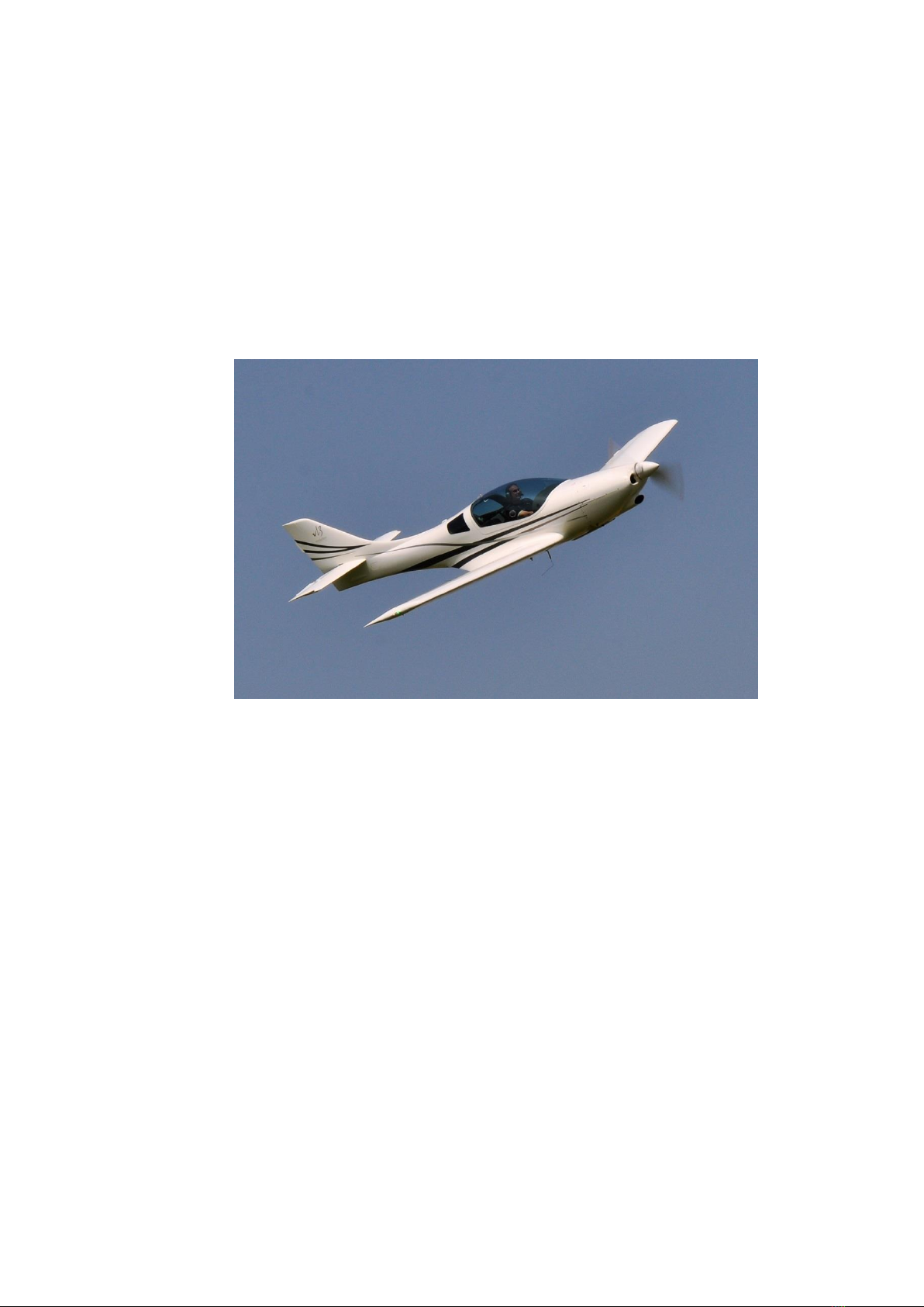
VL-3E-1 Evolution aeroplane is intended for recreational and cross-country flying. It is not
approved for aerobatic operation.
VL-3E-1 Evolution is a single engine, composite aeroplane with two side-by-side seats. The
aeroplane is equipped with retractable tricycle landing gear with a steerable nose wheel. The fuselage
is a carbon shell with carbon/kevlar seats integrated
The wing is a monospar construction with a sandwich skin composed of two layers of carbon
and special foam. Control surfaces and empennage is of the same construction.
The aeroplane is controlled by dual push-pull control system, rudder drive is controlled by
cables and on the right elevator is trim connected by 2 cables with trim lever. The ailerons and elevator
are controlled by the control stick located between the pilot's legs (co-pilot's). The rudder is controlled
by the rudder pedals, flaps are manyally operated by a control lever located between the pilots on the
fuselage main spar.

VL-3E-1 Pilot Operating Handbook
date of issue:
7/40
1.3.2 Basic Technical data
Wing
span …………………………………………… 8.44 m
area of wing …………………………………… 9.8 m2
M.A.C. …………………………………………. 1,236 m
loading …………………………………………. 46 kg/m2
Ailerons
area ……………………………………………... 0.207 m2
Flaps
area ………………………………………………0.8 m2
Fuselage
length ..…………………………………………… 6.2 m
width …………………………………………….. 1.15 m
height …………………………………………….. 1.5 m
Horizontal tail unit
span …………………………………………….. 2.68 m
area ………………………………………………1.69 m2
elevátor area …………….. ………………......... 0.73 m2
Vertical tail unit
height …………………………………………… 1.03 m
area …………………………….……………….. 0.876 m2
rudder area …………………………………….. .0.309 m2
Landing gear
wheel track ……………………………………….1.83 m
wheel base ………………………………………..1.285 m
main wheel diameter ……………………………0.35 m
nose wheel diameter …………………………… 0.3 m

VL-3E-1 Pilot Operating Handbook
date of issue:
8/40
1.4 Two-view drawing
VL-3E-1 Pilot Operating Handbook
date of issue:
9/40
2. Limitations
2.1 Introduction
Section 2 includes Operating limitations, instrument markings, and basic placards necessary for
safe operation of the aeroplane, its engine, standard systems and standard equipment.
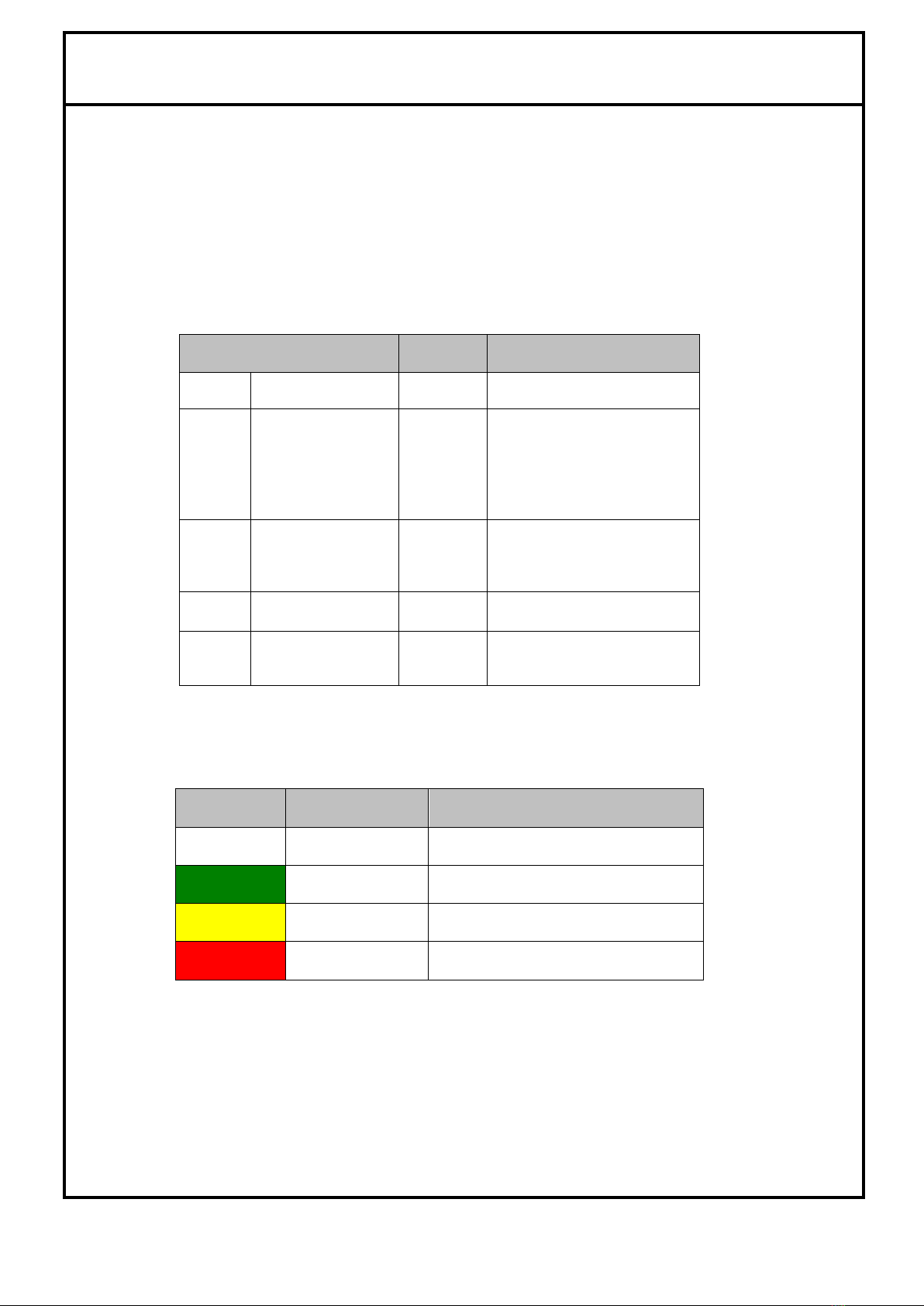
2.2 Airspeed limits
Airspeed limitations and their operational significance are shown below:
Airspeed
IAS
[km/h]
Remarks
VNE
Never exceed
speed
305
Do not exceed this speed in
any operation.
VA
Manoeuvring speed
165
Do not make full or abrupt
control movement above this
speed, because under
certain conditions the aircraft
may be overstressed by full
control movement.
VNO
Maximum
structural
cruising speed
235
Do not exceed this speed
except in smooth air, and
then only with caution.
VFE
Maximum flap
extension speed
120
Do not exceed this speed with
flaps extended
VLE
Maximum landing
gear extension
speed
150
Do not exceed this speed with
undercaridge extended
2.3 Airspeed indicator markings
Airspeed indicator markings and their colour-code significance are shown below:
Marking
Range or value
[IAS km/h]
Significance
White
arc
57 - 120
Positive Flap Operating Range
Green
arc
75 –235
Normal Operating Range
Yellow
arc
235 –305
Manoeuvres must be conducted with
caution and only in smooth air.
Red
line
305
Maximum speed for all operations.

VL-3E-1 Pilot Operating Handbook
date of issue:
10/40
2.4 Powerplant
Engine Manufacturer : Bombardier-Rotax GMBH
Engine Model : Rotax 912 ULS
Power :
Max. Take –off : 73.5 kW / 100 hp
Max. Continuous : 69 kW / 95 hp in 5500 rpm
Cruising : 66 kW / 90 hp in 4800 rpm
Engine RPM :
Max. Take-off : 5800 RPM max 5 min
Max. Continuous : 5500 RPM
Cruising : 4800 RPM
Idling : 1400 RPM
Cylinder head temperature :
Minimum : 60 °C
Maximum : 120 °C
Oil temperature :
Minimum : 50 °C
Maximum : 130 °C
Operating : 90 °C – 100 °C
Fuel pressure (if the fuel gauge and sensor are instaled):
Minimum : 0,15 bar
Maximum : 0,40 bar
Fuel : see chapter 2.13
Oil : (refer to engine Operator’s Manual).
Warning
This engine has not been certified as an aircraft engine
and its failure may occur at any time. The pilot is fully
responsible for consequences of such a failure.
VL-3E-1 Pilot Operating Handbook
date of issue:
11/40
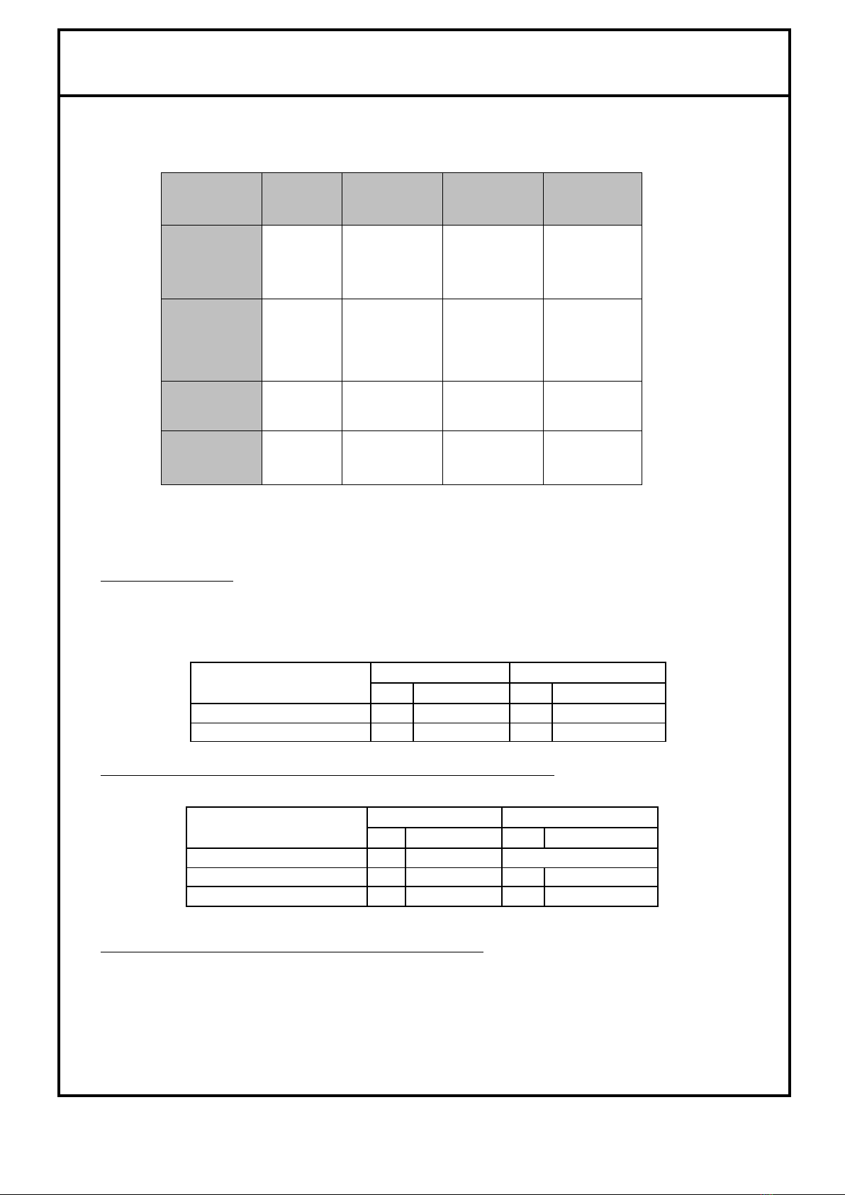
2.5 Engine instrument markings
Function
Minimum
Limit
Normal
Operating
Range
Caution
Range
Maximum
Range
Engine
speed
(RPM)
1400
1400-5500
5500-5800
5800
Cylinder
Head
Temperature
(CHT)
[°C]
74
74-110
100-110
120
Oil
Temperature
[°C]
50
88-110
110-130
130
Oil
Pressure
[bar]
2,0
2,0 –5,0
5,0 –7,0
7,0 cold
engine
starting
2.6 Miscellaneous instrument marking
Fuel Level Indication
Used floater fuel indication system does not allow to indicate exact fuel level in whole range (the
floater contacts the upper wall of the tank before the tanks is filled full). From this reason the following
states of fuel in the tanks are recognised:
Left tank
Right tank
Liter
US gallon
Liter
US gallon
Full tank
59
15.6
59
15.6
Upper indicating limit
40
10.5
40
10.5
Individual fuel level gauges (separate instruments on instrument panel):
The following colour ranges are marked in EMS diagrams for both tanks
Low fuel level indicators (yellow LEDs on instrument panel):
When low fuel level indicator (yellow LED) on the instrument panel starts to light up –in the fuel tank is
min. 5 liters (1,32 US gallon) of fuel.
minimum
maximum
Liter
US gallon
Liter
US gallon
Green range
16
4.2
maximum
Yellow range
8
2.1
16
4.2
Red range
0
0
8
2.1
VL-3E-1 Pilot Operating Handbook
date of issue:
12/40
2.7 Weight
Empty weight (standard equipment) ….…………….. xxxx kg
Max. take-off weight ………..………………………..… 472.5 kg
Max landing weight …………..………………………... 472.5 kg
Max. baggage weight ………..…………………………. 15 kg
2.8 Centre of gravity
Empty aeroplane C.G. position (undercarriage retracted)…... xxxx %MAC
Empty aeroplane C.G. position (undercarriage extended)…... xxxx %MAC
Operating C.G. range …….…………………………………….. 21 - 34 %MAC
2.9 Approved manoeuvres
Aeroplane Category: NORMAL
The aeroplane is approved for Normal and Manoeuvres listed below:
-Steep turn not exceeding 60° bank
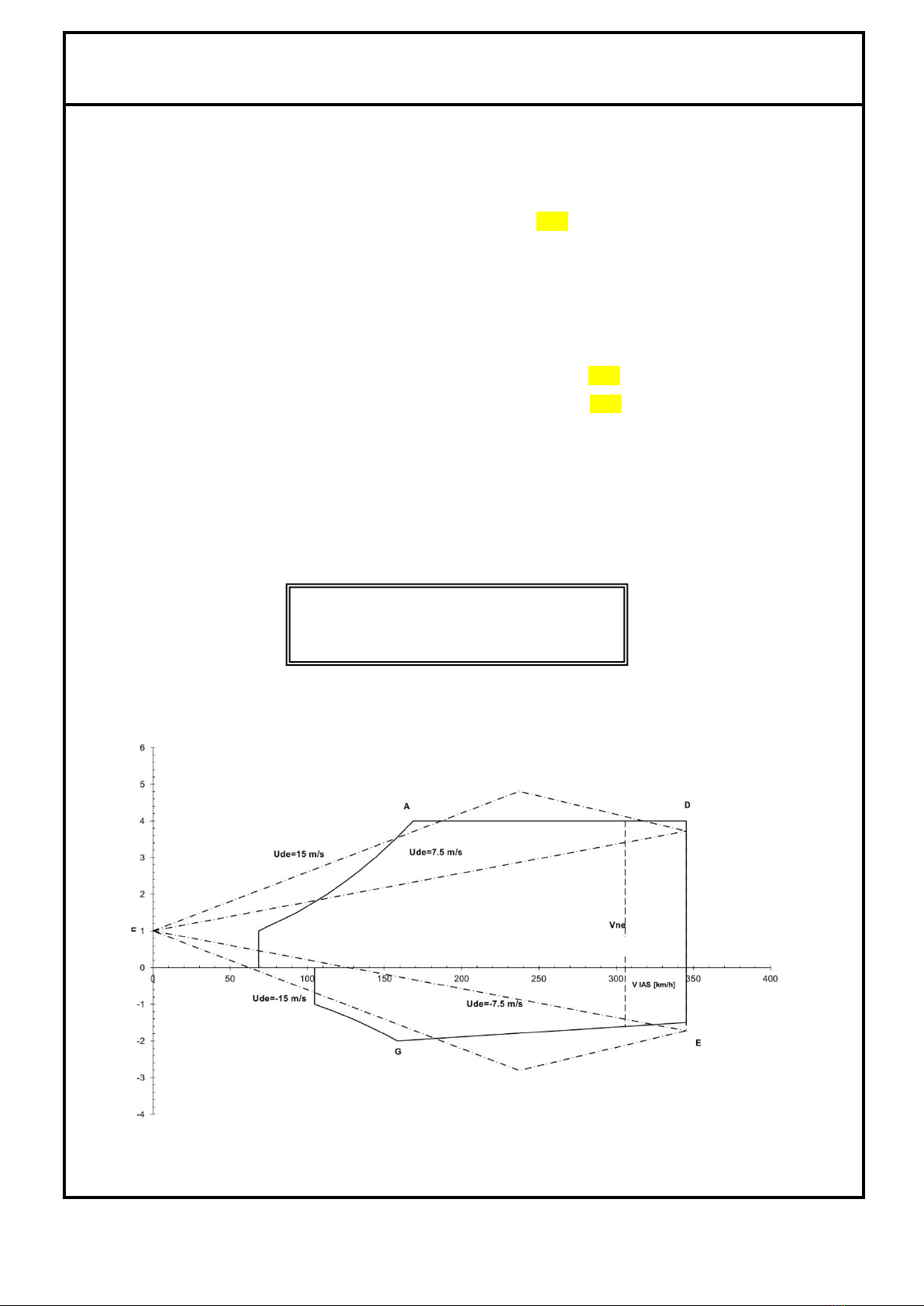
2.10 Manoeuvring load factors
Warning
Aerobatics, intentional spins and stalls
are prohibited!
VL-3E-1 Pilot Operating Handbook
date of issue:
13/40
2.11 Crew
Numer of seats………………………………………… 2
minimum crew weight ……………………………… 65 kg
maximum crew weight ……………………………… see. 6.2
2.12 Kinds of operation
Day VFR flights only.
Instruments and equipment for VFR flights:
1 Airspeed indicator (marked according to 2.3)
1 Altimeter
1 Vertical speed indicator
1 Compass
2 Safety harnesses
2.13 Fuel
WARNING!
Based on experience from the operation of aircraft VL-3 we strongly recommend to use quality
prescribed fuel only! Using the poor quality fuel can cause a major failure in the fuel system!
Don’t use fuels than contain more then 10% of ethanol! These fuels have not been tested by
ROTAX company and are not permited for use!
Recommended fuels:
•Automotive premium grade gasoline, leaded, according to DIN 516000,Ö-NORM C 1103
•EUROSUPER RON 95 unleaded accord. to DIN 51607,Ö-NORM 1100
•AVGAS 100 LL. Due to higher lead content in AVGAS, the wear of valve seats and deposits in the
combustion chamber will increase.Therefore, use AVGAS only if other fuel types are not available
•Mogas European standart EN 228 Super, EN 228 Super Plus
•BA 95 Natural is recommended for Czech Republic
For other suitable fuel types refer to the engine ROTAX Operator’s Manual and ROTAX Service
instruction SI-912-016 for selection of the correct fuel.
2.14 Other limitations
No smoking aboard the aeroplane.
Warning
Never exceed Maximum Take-off Weight

VL-3E-1 Pilot Operating Handbook
date of issue:
14/40
2.15 Limitation placards
Caution
The owner (aeroplane operating agency) of
this aeroplane is responsible for placards readability
during aeroplane service life.
EMPTY WEIGHT xxxx KG
MAX.TAKE-OFF WEIGHT 472,5 KG
MIN.CREW WEIGHT 65,0 KG
MAX. BAGGAGE WEIGHT 15,0 KG
15 KG
Caution
The owner (aeroplane operating agency) of
this aeroplane is responsible for placards readability
during aeroplane service life.
NEVER EXCEED SPEED VNE = 305 KM/H
MANOEUVRING SPEED VA = 165 KM/H
DESIGN CRUISING SPEED VC= 235 KM/H
MAX. FLAPS EXTENSION SPEED VFE = 120 KM/H
STALL SPEED VS0 = 57 KM/H
Power
RPM
manifold
pressure
[1/min]
[in Hg]
Take-off
5800
27.5
continuing
5500
27
75%
5000
26
65%
4800
26
55%
4300
24

VL-3E-1 Pilot Operating Handbook
date of issue:
15/40
3. Emergency procedures
3.1 Introduction
Section 3 provides checklist and amplified procedures for coping with emergencies that may occur.
Emergencies caused by aeroplane or engine malfunctions are extremely rare if proper pre-flight
inspections and maintenance are practised. However, should an emergency arise, the basic guidelines
described in this section should be considered and applied as necessary to correct the problem.
3.2 Engine failure
3.2.1 Engine failure during take-off run
1. Throttle - retard to idle
2. Ignition - off
3.2.2 Engine failure immediately after take-off
1. Speed - gliding at 100km/h (55 kts)
2. Altitude - below 50 m (165 ft) : land in take-off direction
- over 50 m (165 ft) : choose landing area
3. Wind - evaluate direction and velocity
4. Landing area - choose free area without obstacles,into wind
5. Flaps - extend as needed
6. Fuel valve - off
7. Ignition - off
8. Safety harness - tighten
9. Master switch - switch off before landing
10. Land
3.2.3 Engine failure in flight (Forced landing)
1. Speed - gliding at 100km/h (55 kts)
2. Altitude - below 50 m (165 ft) : land in take-off direction
- over 50 m (165 ft) : choose landing area
3. Wind - evaluate direction and velocity
4. Landing area - choose free area without obstacles
5. Flaps - extend as needed
6. Fuel valve - off
7. Ignition - off
8. Safety harness - tighten
9. Master switch - off before landing
10. Land
3.2.4 In-flight engine start
1. Speed - gliding at 120km/h (65 kts)
2. Altitude - check
3. Landing area - choose according to altitude (safest area)
4. Master switch - on
5. Fuel valve - open
6. Choke - as necessary (for cold engine)
7. Throttle - for 1/3 power
8. Ignition - on
9. Starter - turn switch box key

VL-3E-1 Pilot Operating Handbook
date of issue:
16/40
3.3 Smoke and fire
3.3.1 Fire on ground
1. Fuel valve - off
2. Throttle - close
3. Master switch - off
4. Ignition - off
5. Abandon the aeroplane
6. Extinguish fire if possible or call fire department.
3.3.2 Fire during take-off
1. Fuel valve - off
2. Throttle - full
3. Speed - 120 km/h (65 kts)
4. Master switch - off
5. Ignition - off
6. Land and brake
7. Abandon the aeroplane
8. Extinguish fire if possible or call fire department.
3.3.3 Fire in flight
1. Fuel valve - off
2. Throttle - full
3. Ignition - off after using up fuel in carburetors and engine stopping
4. Master switch - off
5. Choose of area - heading to the nearest airport or choose emergency landing area
6. Emergency landing - perform according to par.3.6.1
7. Abandon the aeroplane
8. Extinguish fire if possible or call fire department.
3.4 Glide
Gliding may be used in case of engine failure.
1. Speed - ~ 140 km/h (75 kts)
2. Flaps - retracted
3. Instruments - within permitted limits
Note
Estimated time to pump fuel out of
carburettors is of 30 sec.

VL-3E-1 Pilot Operating Handbook
date of issue:
17/40
3.5 Landing emergencies
3.5.1 Emergency landing
An emergency landing may be carried out due to engine failure and when the engine cannot be
restarted.
1. Speed - 100 km/h (55 kts)
2. Trim - trim the aeroplane
3. Safety harness - tighten
4. Landing gear - go to the open position - see 4.3.8.
If landing gear can not be extended, or field is not acceptable for landing with open landing
gear, do not extend the landing gear!
5. Flaps - as needed
6. COMM - if installed - report your location if it is possible
7. Transponder - if installed –if necessary set transponder to 7700 (ICAO
worldwide emergency code)
8. Fuel valve - off
9. Ignition - off
10. Master switch - off
3.5.2 Precautionary landing
A precautionary landing may be carried out due to low fuel and/or bad weather conditions.
1. Choose landing area, determine wind direction
2. If a COMM is installed - report your plan to land and land area location to nearest ATC
3. Perform low-altitude passage into wind over the right-hand side of the chosen area with flaps
extended to the take-off position at a speed of 60 kts to thoroughly inspect the area
4. Perform flight around the chosen area
5. Landing gear go to the down position - see 4.3.8.
If landing gear can not be extended, or field is not acceptable for landing with open landing
gear, do not extend the landing gear!
6. Perform an approach at increased idling with fully extended flaps
7. Reduce power to idle when over the runway threshold and touch-down at the very
beginning
of the chosen area
8. After stopping the aeroplane switch off all switches, shut off the fuel valve, lock the
aeroplane
and look for a help
3.5.3 Landing with a flat tire
1. Approach - normal
2. Touch down - good tire first, keep the damaged wheel above ground as long as
possible using ailerons
3. Maintain the direction at landing run, applying braking control
3.5.4 Landing with a defective landing gear
1. If the main landing gear is damaged, perform touch-down at the lowest speed possible and
maintain direction during landing run, if possible.
2. If the nose wheel is damaged perform touch-down at the lowest speed possible and hold the
nose wheel off the runway by means of the elevator control as long as it is possible
VL-3E-1 Pilot Operating Handbook
date of issue:
18/40
3.5.5 Landing with landing gear in retracted position
1. Approach - normal
2. Touch down - touch down with minimum speed.
3.5.6 Landing gear emergency extension
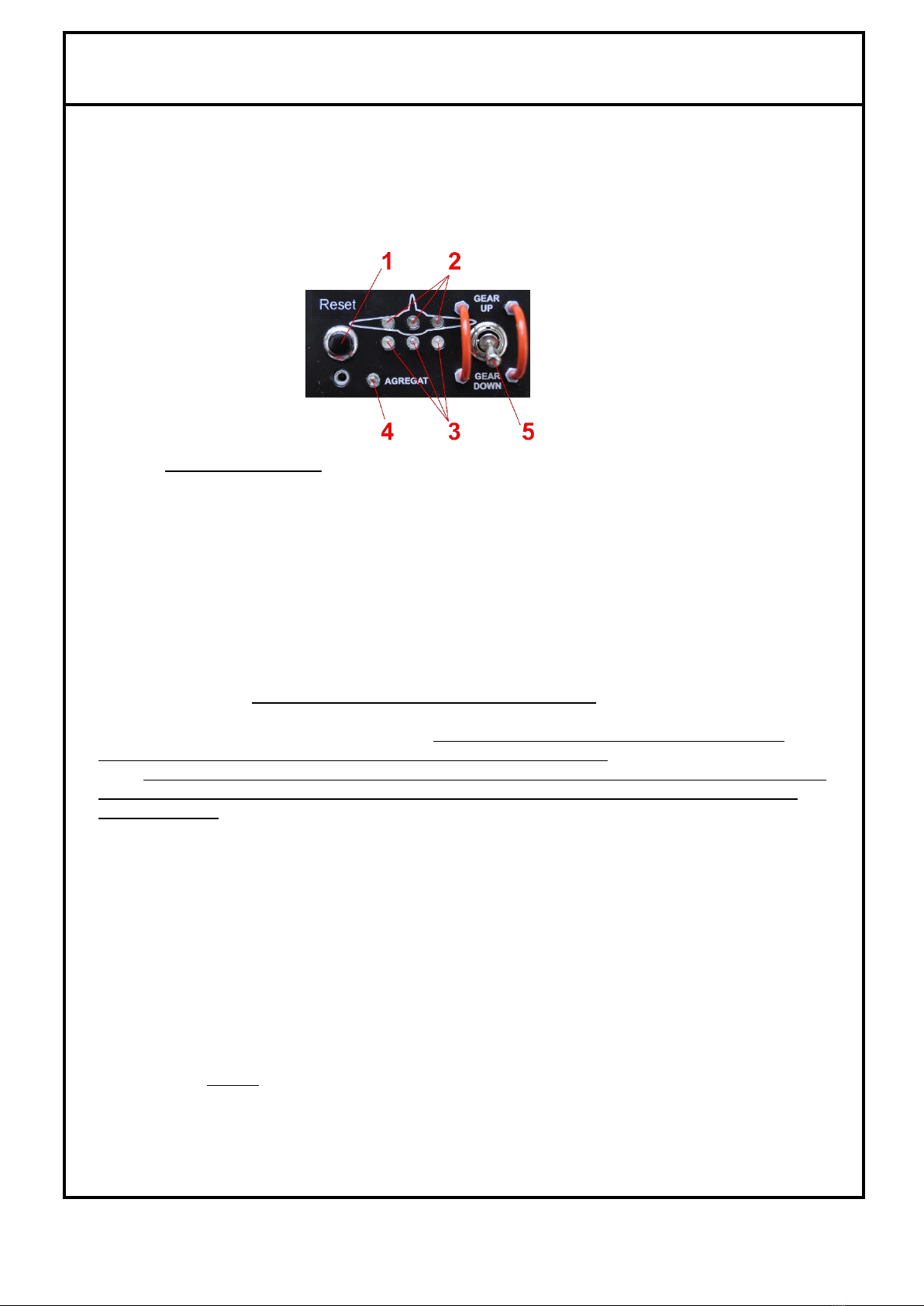
Landing gear controler:
(1) –„Reset“ button
(2) –Three red lights for „GEAR UP“ position
(3) –Three green lights for „GEAR DOWN“ position
(4) –Red light „AGREGAT“
(5) –Switch for retraction and extension of landing gears
This procedure is necessary to use if you don‘t see the three green lights on the „Landing gear
controler“ during the landing gears extension. The hydraulic system for landing gears opening is
programmed to run 30 sec. If after this period the „Landing gear controler“ don’t indicate all three landing
gear sensors in the right position, the red light „agregat“ (4) start flashing and the system will set himself
into „standby status“. In this case push once again the button „Reset“ (1) on the „Landing gear
controler“ and the system will start new cycle of landing gears opening. If the three green lights appears,
landing gears are open and in the right position. After landing of aeroplane is necessary make detail
inspection of undercarriage opening system and find a cause of the defect!
If after reset of „Landing gear controler“ you don’t see the three green lights you must use the hand
pump for „Emergency releace of gears“ (see chapter 7.3 pos.22) for manuel opening of landing gears –
follow next steps:
1. Check fuel level - for estimating the time, you have for an emergency landing
2. Airspeed 120 km/h (65 kts)
3. Switch (5) of „Landing gear controler“ toggle to position „gear down“
4. Landing flaps open to „15°“
5. By the right hand, hold the control stick to fly the plane and by the left hand to grab the
handle of hand pump.
6. By pulling pump handle up, tear off safety wire!
7. Start pumping down untill the hand pump stops (min.35 cycles of compression) and until the
three green lights appears on „Landing gear controler“- it indicate, that landing gears are
open and in the right position.
8. When appears three green lights on the „Landing gear controler“ you can safely land.
9. If THREE green lights will not appears, ask air traffic control tower for visual inspection of
landing gears position. If the air traffic control tower confirm you right position of all three
open landing gears you can safely land.
10. If the air traffic control tower does not confirm you right position of all three landing gears, is
the best solution retract all wheels and make emergency landing without landing gears.
VL-3E-1 Pilot Operating Handbook
date of issue:
19/40
3.6 Recovery from unintentional spin
There is no tendency of spontaneous uncontrollable spin entry if normal pilot techniques are used.
Should an inadvertent spin occur, the following recovery procedure should be used:
1. Throttle - retard to idle
2. Control stick - hold ailerons neutralized
3. Rudder pedals - apply full opposite rudder
4. Control stick - forward elevator control as required to break the spin
5. Rudder pedals - immediately after the stopping of a rotation neutralise the rudder
6. Recover from dive
3.7 Other emergencies
3.7.1 Vibration
If vibrations appears:
1. Set aeroplane speed and engine speed to power setting where the vibrations are the lowest.
2. Land at the nearest airfield or perform a precautionary landing according to 3.5.2
3.7.2 Carburettor icing
Carburettor icing mostly occurs when getting into an area of ice formation. The carburettor icing shows
itself through a decrease in engine power and an increase of engine temperatures.
To recover the engine power, the following procedure is recommended:
1. Speed - 110km/h (60 kts)
2. Throttle - set for 1/3 power
3. If possible, leave the icing area
4. Gradually increase the engine power to cruise condition after 1-2 minutes.
If you fail to recover the engine power, land at the nearest airfield (if possible) or depending on
circumstance, execute a precautionary landing according to 3.6.2
3.7.3 Alternator or power supply failure
1. Switch off immidiately all electric instruments which are not important for flight.
2. Check voltage of the battery and to land soonest on the nearest airport!
3.7.4 Cabin opening in flight
1. Reduce speed - to 100 km/h (55 kts)
2. Landing flaps - on „15°“
3. Trim the plane
4. Close cabin again and resume flight if no damage is observed.
5. Control cabin frame and lock before next flight.
Warning
Intentional spins are prohibited !

VL-3E-1 Pilot Operating Handbook
date of issue:
20/40
3.7.5 Tranceiver communication failure
In the case of radio communication failure follow next steps:
1. Check power supply –status of fuse.
2. Check communication with another ATC.
3. In the case of no communication set tranceiver to 7600 (ICAO worldwide emergency code) to
inform ATC, that your transceiver is out of order.
4. To land soonest on the nearest airport!
Table of contents


