Avery Dennison Mobile Work Station (MWS) Monarch 9876 User manual

©2007 Avery Dennison Corp. All rights reserved.
28028
0
Operating Instructions
®
Monarch 9876™ and 9878
Mobile Work Station (MWS™)
™
TC987xOI Rev. AE10/19
FUSE

Each product and program carries a respective written warranty, the only warranty on which
the customer can rely. Avery Dennison Corp. reserves the right to make changes in the
product, the programs, and their availability at any time and without notice. Although Avery
Dennison Corp. has made every effort to provide complete and accurate information in this
manual, Avery Dennison Corp. shall not be liable for any omissions or inaccuracies. Any
update will be incorporated in a later edition of this manual.
©2007 Avery Dennison Corp. All rights reserved. No part of this publication may be
reproduced, transmitted, stored in a retrieval system, or translated into any language in any
form by any means, without the prior written permission of Avery Dennison Corp.
WARNING
This equipment has been tested and found to comply with the limits for a Class A digital
device, pursuant to Part 15 of the FCC Rules. These limits are designed to provide
reasonable protection against harmful interference when the equipment is operated in a
commercial environment. This equipment generates, uses, and can radiate radio
frequency energy and, if not installed and used in accordance with the instruction manual,
may cause harmful interference to radio communications. Operation of this equipment in a
residential area is likely to cause harmful interference in which case the user will be
required to correct the interference at his own expense.
CANADIAN D.O.C. WARNING
This digital apparatus does not exceed the Class A limits for radio noise emissions from
digital apparatus set out in the Radio Interference Regulations of the Canadian Department
of Communications.
Le présent appareil numérique n’émet pas de bruits radioélectriques dépassant les limites
applicables aux appareils numériques de la classe A prescrites dans le Réglement sur le
brouillage radioélectrique édicte par le ministère des Communications du Canada.
Trademarks
Monarch®, 9876 and 9878 are registered trademarks of Avery Dennison Corporation.
Avery Dennison
170 Monarch Lane
Miamisburg, OH 45342

Getting Started i
TABLE OF CONTENTS
GETTING STARTED ........................................................................................................................1-1
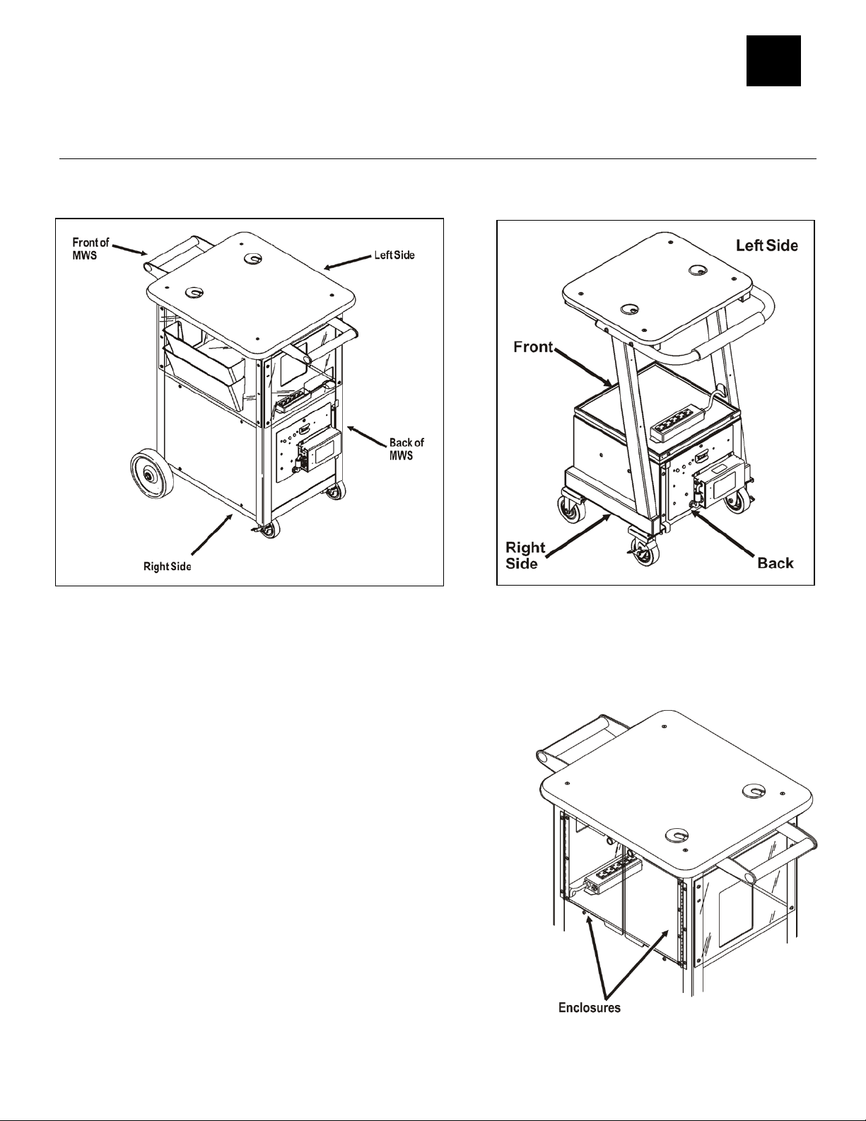
About the MWS..........................................................................................................................1-1
About the 9876 Optional Accessories .......................................................................................1-1
Attaching the Hanging Folders.................................................................................................1-2
Connecting the Power Cord.........................................................................................................1-2
Routing the Cables (9878 MWS)..................................................................................................1-2
Safety Precautions.....................................................................................................................1-3
Audience...................................................................................................................................1-3
Calling Service...........................................................................................................................1-3
CHARGING THE BATTERIES...........................................................................................................2-1
Important Battery Safety Information............................................................................................2-1
Battery Life................................................................................................................................2-2
About the Battery Charger...........................................................................................................2-2
Important Charging Information...................................................................................................2-3
Key Switch .............................................................................................................................2-3
Charger LEDs.........................................................................................................................2-4
Frequency of Charging/Run-Time Guidelines................................................................................2-4
SPECIFICATIONS...............................................................................................................................1
MWS............................................................................................................................................1
Batteries.......................................................................................................................................1
Chargers ......................................................................................................................................2
Two Batteries ............................................................................................................................2
Inverters.......................................................................................................................................2
WIRING DIAGRAMS ...........................................................................................................................1
24v with DC-to-DC Converter, 12v (9876)........................................................................................2
24v with 700w Inverter (9876/9878)................................................................................................3
24v with 1,000 Watt Inverter (9876/9878)........................................................................................4


Getting Started 1-1
GETTING STARTED
Use the Monarch® 9876™ and 9878™ Mobile Work Station™ (MWS™) for mobile
printing.
About the MWS
The MWS ships mostly assembled. There are optional accessories available for the 9876
MWS that may require some assembly.
About the 9876 Optional Accessories
To assemble the options, you may need a 5/32" Hex wrench, and a Phillips screw driver.
The 9876 MWS has combinations of doors and solid panels. The door enclosures should
already be attached to the MWS.
Note: Use water or a glass and surface cleaner to
clean the door enclosures. Do not use solvents
on these enclosures. A solvent will damage the
door enclosure.
12
9878 MWS
9876 MWS

1-2 Operating Instructions
Fuse
Charger Power Switch
Power Inlet
24V Charger
Attaching the Hanging Folders
Follow the steps below to attach the hanging folders to the
9876 MWS. .
1. Remove the following items from their packaging:
(1) file folders
(4) 3/8" plastite screws (may already be attached to
panel)
2. Use the assembly instructions provided with the file
folders to assemble folders to the MWS panel.
3. Tighten the screws.
Connecting the Power Cord
Connect the charger's power cord to the power inlet. Power cords are not included with
International models.
Note:The charger’s power switch does not control the MWS power. The MWS power switch
located on the power panel controls power to the MWS and connected devices.
Routing the Cables (9878 MWS)
Use the four access holes to route the
cables on the MWS.

Getting Started 1-3
Safety Precautions
The following symbols are used in this manual to show the importance of safety when using
the MWS.
WARNING Failure to follow the guidelines marked with this symbol could result in
serious personal injury or death.
CAUTION Failure to follow the guidelines marked with this symbol could result in minor
personal injury or product damage.
Caution, risk of electrical shock. Also known as the "High Voltage" symbol.
Audience
This manual is designed for the person using the MWS for mobile printing applications.
After you receive the MWS, you should have all the necessary parts, including the batteries
and charger. Keep the boxes and packaging material in case the MWS ever needs repair.
Calling Service
If these solutions do not work or you have a problem not listed, see your System Administrator
or call Service at the number listed on the back of this manual.

1-4 Operating Instructions

Charging the Batteries 2-1
CHARGING THE BATTERIES
The battery charger is a fully automatic, maintenance-free charger. Dispose of used
batteries according to the manufacturer’s instructions.
CAUTION: The charger's power switch does not control MWS power. The MWS power switch,
located on the power panel, controls power to the MWS and connected devices.
To charge the battery, plug the MWS’s AC power cord into a grounded outlet.
Charge the battery:
♦before using the MWS for the first time (charge it for 7 hours)
♦when the MWS beeps (see “Battery Life” for indications of low battery conditions)
♦when the MWS is not in use.
You may be able to operate equipment connected to the MWS for up to four hours while the
cart is charging.However, use of MWS equipment results in slower charge rates.
For optimal performance, we recommend that you turn off all equipment and allow the MWS to
achieve a full charge before returning the MWS to use.
You cannot overcharge the battery. The battery charger is “intelligent”; it monitors the battery
condition and does not overcharge the lead acid battery. Battery life is extended by frequent
charging.
CAUTION: Only qualified service personnel may install or replace the two 12-volt
(55 or 75 amp-hours) sealed lead-acid non-venting batteries on the MWS.
If replacing batteries, you must use the same type of battery from the same manufacturer
(as the ones provided with the MWS). Make sure the batteries are NRTL-recognized.
Also, BOTH batteries MUST be replaced at the same time to maintain capacity match.
Important Battery Safety Information
♦Never smoke or allow a spark or flame in vicinity of battery.
♦Do not drop a metal tool on the battery. The resulting
spark or short-circuit on the battery of other electrical part
may cause an explosion.
♦Remove personal metal items such as rings, bracelets,
necklaces, and watches when working with a lead-acid
battery. A lead-acid battery produces a short-circuit current
high enough to weld a ring to metal, causing a severe burn.
2

2-2 Operating Instructions
Battery Life
The MWS Battery Status LEDs are located on the top-left side of the Power Panel. To use the
Battery Status LEDs, the MWS must be on.
If you leave the battery charger plugged in and constantly charging when the MWS is not in
use (turn MWS power off), the battery life is maximized for the application. The charger does
not overcharge the batteries.
The MWS has signal lights to indicate the battery status as follows. The following voltages are
an approximation and should be used for reference only.
Flashing Orange Warning! The batteries need immediate charging. The MWS beeps
continuously to alert you of this condition. (Early models have red lights
instead of orange).
Flashing Yellow Caution! Finish printing the batch, then recharge the MWS. The batteries
are getting low.
Flashing Green Go! The batteries are charged to approximately 75% or better capacity.
If the CHARGE light does not turn on, make sure the charger is properly connected to the
batteries and the charger has AC power.
If the READY light does not turn on after 18 hours, the batteries are deeply discharged. Call
Technical Support or replace the batteries.
About the Battery Charger
♦Store the charger in a dry area not subject to prolonged below freezing temperatures.
♦The “intelligent” battery charger monitors the batteries condition and does not overcharge
the batteries. It is recommended to leave the battery charger plugged in and charging
when the MWS is not in use. Battery life is extended by frequent charging.
♦The charger’s Green light is on when the battery is finished charging. Leaving the charger
plugged in prevents the battery from self-discharging.
♦The MWS Battery Status LEDs provide the most accurate indication of battery status. While
the 24VDC charger has Percentage LEDS that also show battery status, use the three
Battery Status LEDS on the Power Panel.
MWS Power Switch

Charging the Batteries 2-3
Important Charging Information
WARNING: DANGER! RISK OF ELECTRICAL AND FIRE HAZARD. CERTAIN ACTIONS MAY
RESULT IN DEATH, SERIOUS INJURY, SHOCK, OR BURNS.
♦Do not disassemble the battery charger.
♦Do not operate the charger if it has been damaged in any way. Do not spill liquids into the
charger, such as water or soft drink.
♦Do not expose the battery charger to rain or snow. Never charge a frozen battery. The
colder the battery, the longer it takes to charge.
♦Plug only into a three-prong grounded outlet. Do not alter the AC power cord or plug
provided. Do not operate the battery charger with a damaged cord or plug.
♦Do not let the battery remain fully or partly discharged for a long time; keep it charged.
♦If using an extension cord, you must use 18 gauge or heavier for lengths up to 50 feet, or
16 gauge or heavier for lengths up to 100 feet. Use of improper extension cord could cause
fire and electric shock. Use an extension cord bearing the UL listing mark and rated for
four Amperes or greater current capacity.
♦Pull on the plug rather than the cord when disconnecting the battery charger. Locate the
cords where they will not be stepped on, tripped over, or otherwise subjected to damage or
stress.
♦The batteries must be charged when the total voltage is less than 21V. The charger will not
charge if the total voltage is less than 5V. If the total voltage is less than 5V, you need new
batteries.
Key Switch
The key switch requires the key to turn on/off the mobile work station’s power. The key cannot
be removed when the cart’s power is ON. When storing the mobile work station, keep the key
in a secure location. Losing the key will result in a Service call and replacement of the part;
there is not a master key.
Note: Use the clip on the power cord to secure it in place.

2-4 Operating Instructions
Charger LEDs
Use this table to read the charger’s LEDs:
Description Status
Red LED Yellow LED Green LED
Calibrating charger BLINKING OFF BLINKING
Preparing to charge OFF ON OFF
Charging ON OFF OFF
Completing charge ON BLINKING OFF
Batteries are charged (fan off) OFF OFF ON
Error BLINKING ON BLINKING
Note: Chargers using firmware version 3.0 and later indicate firmware version using LED
blinks. For example, upon power up, a charger with firmware version 3.0 will indicate
this with three Red LED blinks (the green LED will not blink). Subsequent releases,
such as version 3.2 will indicate with three Red LED blinks and two Green LED blinks.
Frequency of Charging/Run-Time Guidelines
The following information is approximate and should be used for reference. Many factors
affect an individual battery’s performance:
♦the presence of auxiliary devices
♦the printing rate (including printhead contrast and number of labels per day)
♦the complexity of your printed formats
♦the environment (temperature and humidity in your facility or DC).
“Typical conditions” are defined as:
one Monarch printer printing standard compliance 4x6 labels (5-10 minutes of actual printing
per hour), no auxiliary devices attached to the MWS, and standard environmental conditions
(no excessive heat or humidity).
♦When using the 24VDC or Symbol 24VDC MWS under typical conditions, the batteries may
last up to 50 to 100 hours before recharging.
♦When using the AC Power Inverter or 24VDC/115VAC MWS under typical conditions, the
batteries may last up to 24 hours before recharging.
♦When you notice the batteries need to be charged more frequently, order replacement
batteries. BOTH batteries MUST be replaced at the same time to maintain capacity
match. For example, if you had 60 hours of use between charges and now have 30 hours
of use between charges, replace the batteries.
Note: The performance of your batteries varies depending on the number of printers and/or
auxiliary devices, such as a scanner or terminal, attached to the MWS.
Frequent charging of the batteries is recommended.
Turn off the MWS power switch (which turns OFF all connected equipment)
whenever the MWS will be idle for an extended period of time.

Specifications A-1
SPECIFICATIONS
MWS
The specifications for the 9876 and 9878 mobile work stations are listed below.
9876 9878
Height: ≈42 inches (1067 mm)
depending on selected options ≈37 inches (940 mm)
depending on selected options
Top Width: 23 inches (584 mm) 20.5 inches (521 mm)
Length: 28 inches (711 mm) 22 inches (559 mm)
Weight: ≈225 lbs (103 kg)
depending on selected options ≈115 lbs (52 kg)
depending on selected options
Power Cabinet
Lower Shelf: N/A 15 inches wide x 16 inches
long (381 mm x 406 mm)
Top Shelf :
(Laminated Top) N/A 20 inches wide x 16 inches
long (508 mm x 406 mm)
Operating Limits: 40°F to 95°F (5°C to 35°C)
with thermal transfer supplies 40°F to 95°F (5°C to 35°C)
with thermal transfer supplies
Storage: 15°F to 120°F (-9°C to 49°C) 40°F to 120°F (5°C to 49°C)
Humidity: 5% to 90% non-condensing 5% to 90% non-condensing
Batteries
♦(2) 12-volt, 55 amp-hours or 75 amp-hours, AGM (non-flooded) deep cycle batteries.
The batteries are labeled with the amp hour and voltage information.
♦Sealed lead-acid, non-venting (safety venting only), no transportation restrictions.
♦Shelf Life/Charge Retention:
1 month 97%
3 months 91%
6 months 85%
♦Cycle Use:
100% depth of discharge approx. 250 cycles
50% depth of discharge approx. 550 cycles
30% depth of discharge approx. 1200 cycles
Cycle Life is approximate and many factors affect an individual battery’s performance.
3

A-2 Operating Instructions
Chargers
Two Batteries
Input 180-264 VAC @ 3.0 - 1.5 A
50/60 Hz
IEC 320-C14 Connection
Output 24 VDC, 8 Amps DC charging current
♦Reverse polarity and short circuit-proof
♦8 to 11 hours full charge, typical recharge time is 3 to 8 hours
The recharge time depends on the battery size and amount of charge remaining.
♦20 to 100 hour typical battery duration
The duration varies based on the equipment powered by the Mobile Work Station and the
frequency of use for the equipment.
♦Smart charging
Note: Use only NRTL-listed (National Recognized Testing Lab) accessories.
Inverters
Two inverters are available: 700 or 1,000 watt.
700 watt 1,000 watt
Input Voltage: 21 to 33VDC 21 to 30VDC
No Load Current: 0.8A 0.75A
Frequency: 50/60 Hz ± 0.3% 50/60 Hz ± 0.3%
Output Voltage: 110VAC ± 5% 110VAC ± 3%
Output Power: 700W RMS (continuous) 1000W RMS (continuous)
Surge Power: 1000W RMS (1 second) 2000W RMS (1 second)
Output Waveform: Pure Sine Wave (THD<3%) Pure Sine Wave (THD<3%)
Typical Efficiency: 93% 92%
Operating
Temperature -4°F to 105°F (-20°C to 40°C) 32°F to 105°F (0°C to 40°C)

Wiring Diagrams B-1
WIRING DIAGRAMS
This appendix contains wiring diagrams for the various power options:
♦24v with DC-to-DC Converter, 12v (9876)
♦24v with 700w Inverter (9876)
♦24v with 1,000 Inverter (9876/9878)
WARNING Only qualified service personnel may install or replace the two 12-volt sealed lead
acid batteries used to power the printer on the Station.
If a battery needs to be replaced, BOTH batteries MUST be replaced at the same time to
maintain capacity match. One or two power sparks may occur (this is normal) when installing
or changing the fuses.
A

B-2 Operating Instructions
24v with DC-to-DC Converter, 12v (9876)

Wiring Diagrams B-3
24v with 700w Inverter (9876/9878)

B-4 Operating Instructions
24v with 1,000 Watt Inverter (9876/9878)


28028
0
Avery Dennison
170 Monarch Lane
Miamisburg, OH 45342
1-800-543-6650 (In the U.S.A.)
1-800-387-4740 (In Canada)
www.monarch.com
Other manuals for Mobile Work Station (MWS) Monarch 9876
1
This manual suits for next models
1
Table of contents
Other Avery Dennison Desktop manuals