AVGear AVG-UDATP4 User manual

AVG-UDATP4
The AVG-UDATP4 is an HDBaseT Splitter
accepting 1 HDMI input and distributing it to 4
HDBT outputs, plus 1 HDMI local output.
Features
Compliant with HDMI 1.4 & 3D
Transmit 4K x 2K signal up to 40m
and 1080p signal up to 60m
Supports PoC
Supports IR control and cascade
control
Supports RS232 control and
cascade control
Real-time display of working status
via LED indicators
Supports EDID configuration, 5
types in total
Supports cascading via HDMI OUT,
IR Loop and RS232 Loop

AVG-UDATP4
PLEASE READ THIS PRODUCT MANUAL CAREFULLY
BEFORE USING THIS PRODUCT.
This manual is only for operational instruction only,
and not to be used for maintenance. The functions
described in this version are current as at March 2015.
Any changes of functions and operational parameters
will be updated in future manual versions. Please refer
to your dealer for the latest product details.
Version 1.0 1/3/15

AVG-UDATP4
SAFETY OPERATION GUIDE
In order to guarantee the reliable operation of the equipment and safety of the
user, please abide by the following procedures in installation, use and
maintenance:
1. The system must be earthed properly. Please do not use two blade plugs
and ensure the AC power supply ranges from 100v to 240v and from 50Hz
to 60Hz.
2. Do not install the switcher in an environment where it will be exposed to
extreme hot or cold temperatures.
3. This unit will generate heat during operation, please ensure that you allow
adequate ventilation to ensure reliable operation.
4. Please disconnect the unit from mains power if it will be left unused for a
long time.
5. Please DO NOT try to open the casing of the equipment, DO NOT attempt to
repair the unit. Opening the unit will void the warranty. There are high
voltage components in the unit and attempting to repair the unit could result
in serious injury.
6. Do not allow the unit to come into contact with any liquid as that could result
in personal injury and product failure.

AVG-UDATP4
TABLE OF CONTENTS
Introduction ..............................................................................................................1
Introduction to the AVG-UDATP4.................................................................1.1
Features.......................................................................................................1.2
Package List ................……………………………………………………………………2
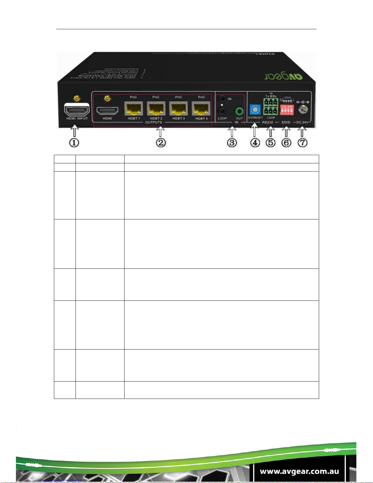
Product Appearance of the AVG-UDATP4 .............................................................3
Front Panel...................................................................................................3.1
Rear Panel....................................................................................................3.2
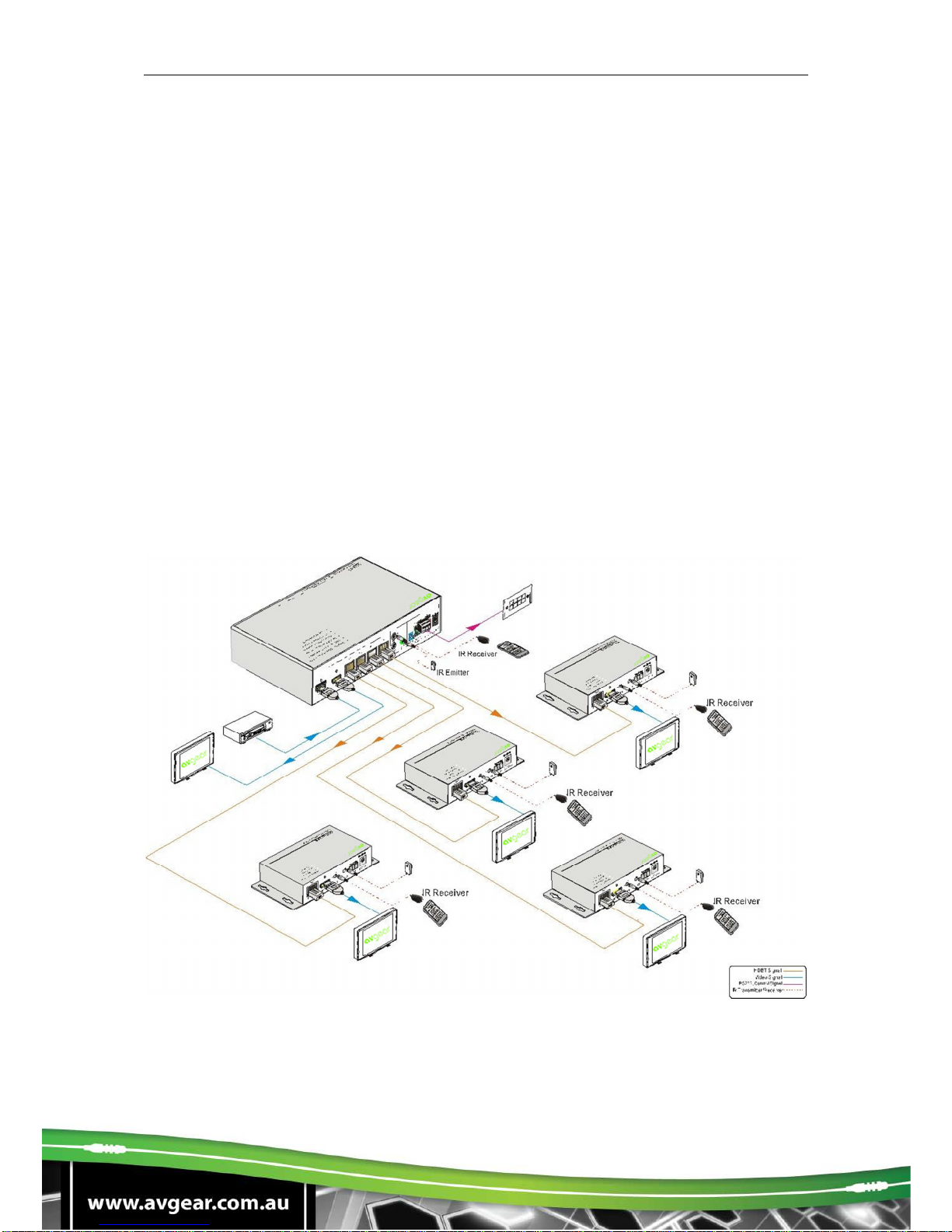
System Connection..................................................................................................4
System Applications.....................................................................................4.1
Usage Precautions.......................................................................................4.2
Connection Diagram.....................................................................................4.3
Connection Procedure..................................................................................4.4
Cascade Connection
......................................................................................4.5
Cascade AV Signal
..........................................................................4.5.1
Cascade Control Signal
....................................................................4.5.2
Twisted Pair Cable Connection
......................................................................4.6
System Operations...................................................................................................5
IR Control.....................................................................................................5.1
Control far-end device from local
......................................................5.1.1
Control far-end device from remote
...................................................5.1.2
RS232 Control..............................................................................................5.2
Installation/Removal of RS232 Control Software
...............................5.2.1
Basic Settings.................................................................................5.2.2
Control far-end device from local
......................................................5.2.3
Control far-end device from remote
...................................................5.2.4
Specifications...........................................................................................................6
Panel Drawing ..........................................................................................................7
Troubleshooting & Maintenance.............................................................................8

AVG-UDATP4
1. Introduction
1.1. Introduction to the AVG-UDATP4
The AVG-UDATP4 is an HDBaseT Splitter accepting 1 HDMI input and distributing it
to 4 HDBaseT outputs, plus 1 HDMI local output. The HDMI output socket can be
used to monitor local devices or cascade with an additional splitter.
Th eAVG-UDATP4 allows uncompressed 4K (max) HDMI, IR, and RS232 signals to
be transmitted over a single CAT5e/6/7 cable. It supports transmission of 4K signals
up to 40m and 1080p signals up to 60m. If required, use the HDMI local output to
cascade the HDMI signal up to 4 times with additional AVG-UDATP4.
The AVG-UDATP4 is also capable of bi-directional IR transmission, EDID
management and PoC.
The AVG-HD402PR HDBaseT receivers are recommended to utilize the full
functionality of the HDBaseT outputs of this device.
1.2. Features
Compliant with HDMI 1.4 & 3D
Transmit 4K x 2K signals up to 40m and 1080p signal up to 60m
Supports PoC
Supports IR control and cascade control
Supports RS232 control and cascade control
Real-time display of working status via LED indicators
Supports EDID configuration, 5 types in total
Supports cascading via HDMI OUT, IR Loop and RS232 Loop

AVG-UDATP4
2. Package List
1 x AVG-UDATP4
2 x Mounting ears (6 x Screws)
8 x Screws
1 x 3.5mm Male-male Audio cable (used for IR signal cascade)
1 x RS232 cable (3-pin captive connector to DB9)
1 x RS232 cable (connect 2 3-pin captive connectors for cascading)
4 x Plastic cushions
1 x Power Cord
1 x Power Adapter (DC 24V)
1 x User manual
Note: Please confirm if the product and the accessories are all included, if not,
please contact your dealer.

AVG-UDATP4
3. Product Appearance of the AVG-UDATP4
3.1. Front Panel
No.
Name
Description
①
Power
Illuminates red once powered on
②
FIRMWARE
USB port, used for firmware updates.
③
INPUT
Illuminates green when there is input signal.
④OUTPUTS
HDMI:
illuminates green when the HDMI source signal
contains HDCP
blinks green when the HDMI source signal is without
HDCP
LINK:
Indicates linking status of the four HDBT sockets
corresponding to the four HDBT sockets separately.
illuminates green when the corresponding HDBT
socket is connected to AVG-HD402PR successfully
turns off when there is no AVG-HD402PR connected
to the corresponding socket.
HDCP:
HDCP compliance indicator, corresponds with the
receivers connected to the four HDBT ports
illuminates green when the corresponding receiver is
receiving HDCP
blinks green when the corresponding receiver is
without HDCP
3.2. Rear Panel

AVG-UDATP4
No.
Name
Description
①
HDMI INPUT
Connects with an HDMI source device such as DVD/ Blu-ray
②
OUTPUTS
HDMI: Connect to a HDMI display or cascade HDMI AV
signal to other displays by connecting to the HDMI INPUT
port of the other AVG-UDATP4
HDBT: HDBaseT output ports with PoC, 4 in total, connect
with IR receivers to transmit HDMI signal
③IR
IN: Connect with IR Receiver to receive IR signal from IR
Emitter.
LOOP: Cascade IR control signal to another HDBT Splitter
by
connecting to its IR IN socket
OUT: Connect with IR emitter to emit the IR signal received
from the receiver side.
④
ID PRESET
Assign ID for the AVG-UDATP4 to identify every unit, the
value may vary from 0~F.
After assigning ID, restart th eAVG-UDATP4 for stable
performance.
⑤ RS232
IN: connect with control device through 3-pin captive cable
LOOP: cascade RS232 control signal to another splitter by
connecting to its RS232 IN port
Note: Please set the communication protocol parameters
correctly, and refer to RS232 commands referring to
instructions in 3.6 RS232 Control.
⑥
EDID DIP
Switchers
4-pin EDID DIP switchers, “1” stands for “On”, “0” stands for
“Off”. Dial the switches to change EDID data referring to the
explanations in 4.3 EDID Management.
⑦
DC 24V
Plug a 24V DC power adapter into this socket and tighten the
screw.
Note: Pictures shown in this manual are for reference only

AVG-UDATP4
4. System Connection
4.1. System Applications
Reliable performance for control and transmission makes the AVG-UDATP4 ideal in
residential installations, signal monitoring, large screen displays, conference
systems, television broadcast, education, banking and security institutions etc.
4.2. Usage Precautions
1. System should be installed in a clean environment with temperature and humidity
maintained to within equipment specifications.
2. All of the power switches, plugs, sockets and power cords should be insulated
and safe.
3. All devices should be connected before power is turned on.
4.3. Connection Diagram
Note: Pictures shown in this manual are for reference only

AVG-UDATP4
4.4. Connection Procedure
Step 1. Connect an HDMI source device (e.g. Blu-ray DVD) to the HDMI INPUT
socket of the AVG-UDATP4 with an HDMI cable.
Step 2. Connect an HDMI display to HDMI OUTPUT socket of AVG-UDATP4 with
an HDMI cable.
Step 3. Connect AVG-HD402PR(s) to HDBT output port(s) of AVG-UDATP4 with
twisted pair.
Step 4. Connect control device (e.g. PC) to the RS232 IN port of AVG-UDATP4 or
AVG-HD402PR (bi-directional RS232 control, either end is available).
If you want to cascade RS232 signals among several AVG-UDATP4 units
through the RS232 LOOP, connect the RS232 LOOP socket of one of
them and the RS232 IN socket of the next until all the AVG-UDATP4 units
have been connected.
Step 5. Connect an IR Receiver to the IR IN port, and an IR Emitter to the IR OUT
port. The IR signal can be transmitted bi-directionally between AVG-
UDATP4 and AVG-HD402PR(s).The IR signal is 5volt.
If you want to cascade the IR signal among several AVG-UDATP4 units,
connect the IR LOOP socket of one of them and the IR IN socket of the
next until all the AVG-UDATP4’s have been connected.
Step6. Connect a DC 24V power adapter to the power port of the AVG-UDATP4,
the AVG-HD402PR is able to be powered by the AVG-UDATP4 using the
PoC capability that is built in.
4.5. Cascade Connection
4.5.1. Cascade AV Signal
HDMI source signals can be cascaded to several displays via HDMI OUT/ IN.
Connect the HDMI OUT socket of the first AVG-UDATP4 to the HDMI IN socket of
the next until all AVG-UDATP4 units have been connected.
HDMI signals connected to the first AVG-UDATP4 are able to be output to
other connected AVG-UDATP4 units as well.
4.5.2. Cascade Control Signal
The AVG-UDATP4 supports control cascading via IR LOOP/ RS232 LOOP to
enable signal loop output. Users can choose one or multiple cascade methods
according to their specified needs.

AVG-UDATP4
Cascade connection diagram:
Cascade through IR Loop
Connect the IR LOOP socket of the first AVG-UDATP4 and the IR IN socket of the
next until all th eAVG-UDATP4 units have been connected.
Sending IR signals to the IR Receiver connected to the first AVG-UDATP4 will
control all cascaded AVG-UDATP4’s.
Cascade through RS232 Loop
Connect the RS232 LOOP socket of the first AVG-UDATP4 and the RS232 IN
socket of the next until all the AVG-UDATP4 units have been connected.
Sending RS232 commands will control all cascaded AVG-UDATP4 simaltaneously.
Note: To identify the AVG-UDATP4 in cascading, please set a unique ID for each
unit when the cascade connection is done.
4.6. Twisted Pair Cable Connection
The twisted pair used in the AVG-HD402PR MUST be a straight-through cable. The
connectors can be T568A or T568B, but both sides must be the same

AVG-UDATP4
TIA/EIA T568A
TIA/EIA T
568B
Pin
Cable color
Pin
1
green white
1
orange white
2
green
2
orange
3
orange white
3
green white
4
blue
4
blue
5
blue white
5
blue white
6
orange
6
green
7
brown white
7
brown white
8
brown
8
brown
1st
4--5
1st
4--5
Ground
Ground
2nd
3--6
2nd
1--2
Ground
Ground
3rd
1--2
3rd
3--6
Group
Group
4th
7--8
4th
7--8
Group
Group

AVG-UDATP4
5. System Operations
5.1. IR Control
By using IR & HDBaseT transmission technology, the AVG-UDATP4 has the
following functions:
1. Control a far-end output device from local matrix location.
2. Control a local input/output device remotely.
3. Control the AVG-UDATP4 locally or remotely.
5.1.1. Control a far-end device from local unit
Control the AVG-UDATP4 or far-end display device from local through
corresponding IR remote.

AVG-UDATP4
5.1.2. Control a far-end device from remote location
Control the AVG-UDATP4 or local display remotely via corresponding IR remote
As RS232 can be transmitted bi-directionally between the AVG-UDATP4 and the
AVG-HD402PR, it is able to control a third party RS232 device locally or control the
AVG-UDATP4 from a remote location.
When controlling a third party RS232 device, the baud rate of this device should be
9600.

AVG-UDATP4
5.2. RS232 Control
5.2.1. Installation/Removal of RS232 Control Software
Installation Copy the control software file to the computer connected with the
Matrix.
Removal Delete all the control software files in corresponding file path.
5.2.2. Basic Settings
Firstly, connect the AVG-UDATP4 with an input device and an output device. Then,
connect it with a computer which is installed with RS232 control software. Double-
click the software icon to run this software.
Here we take the software CommWatch.exe as example. The icon is shown as
below:

AVG-UDATP4
The interface of the control software is shown below:
Please set the parameters of COM number, baud rate, data bit, stop bit and the
parity bit correctly, only then will you be able to send commands in the Command
Sending Area.
Command format: ID +Port number +RS232 command.
Of which port number stands for the HDBT port that the device to be controlled
is connected to, the value varies from 1~4.
For example, if the ID of the AVG-UDATP4 is 01, and the device to be controlled is
connected to HDBT port 2, then send the command “1B1.” as “0121B1.”.
Note: To control AVG-UDATP4 via RS232 port, the communication protocol
parameters should be configured in the right manner: Baud rate: 9600; Data bit: 8;
Stop bit: 1; Parity bit: none.
5.2.3. Control a far-end device locally
Connect the RS232 ports of the AVG-UDATP4 and AVG-HD402PR (See Figure
Below), then it is able to control the AVG-UDATP4 and far-end device from local
position by sending RS232 commands.
Parameter
Configuration area
Monitoring area,
indicates whether
the command sent
works.
Command Sending
area

AVG-UDATP4
5.2.4. Control a far-end device from remote location
Connect the RS232 ports of the AVG-UDATP4 and AVG-HD402PR (See Figure
Below), then it is able to control the AVG-UDATP4 or local display remotely by
sending RS232 commands.

AVG-UDATP4
The AVG-UDATP4 is designed with a 4-pin EDID DIP switch, “1” stands for “On”, “0”
stands for “Off”. Select the switches to change EDID data with reference to the
following table:
Switcher Status
EDID information
0000 (default)
pass through, auto
process
0001
1080P 2D
0010
1080P 3D
0011
720P 2D
0100
720P 3D
0101 (Optional)
DVI 1920x1080
Note: EDID data is subject to change in further firmware versions. Please refer to
the details of further updated firmware.

AVG-UDATP4
6. Specifications
Items
Description
Video
Input/output
VESA and SMPTE 480p to 2160p(4K) With 3D
Bit depth: 16, 20, 24
All HDMI audio formats including
Dolby D (TrueHD)/ DTS
(HD-Master Audio)/ PCM
Audio
Input/output
Channel count: from 2-8 (2.0 to 7.1)
Sample rates: 32 kHz, 44.1 kHz, 48 kHz, 88.2 kHz, 96 kHz,
176.4 kHz and 192 kHz
Power Supply
DC 24V
HDBT
60m (196feet) with HDMI video, RS232 & IR control, PoC
supports AVG-HD402PR
Control
RS232 & IR Full function pass though; 5V IR
RS232 port ID selectable for cascading, Baud Rate 9600
Dimensions
220 x 148 x 44mm (half rack wide)
Raw Materials
Aluminum chassis
Installation
Standard Rack size, provide removable ears for mounting
under table, or on wall

AVG-UDATP4
7. Panel Drawing
Table of contents
Other AVGear Cables And Connectors manuals