Avigilon ACC VMA-RPA-4P2 User manual

User Manual
Avigilon ACC™ ES Analytics Appliance
VMA-RPA-4P2 and VMA-RPA-4P4
(ACC ESfirmware releases 1.4.8.50 and earlier)

©2017 -2018,Avigilon Corporation. All rights reserved. AVIGILON, the AVIGILON logo, AVIGILON CONTROL
CENTER, ACC, and TRUSTED SECURITY SOLUTIONS are trademarks of Avigilon Corporation. Other names or
logos mentioned herein may be the trademarks of their respective owners. The absence of the symbols ™ and ®
in proximity to each trademark in this document or at all is not a disclaimer of ownership of the related
trademark. Avigilon Corporation protects its innovations with patents issued in the United States of America and
other jurisdictions worldwide (see avigilon.com/patents). Unless stated explicitly and in writing, no license is
granted with respect to any copyright, industrial design, trademark, patent or other intellectual property rights of
Avigilon Corporation or its licensors.
This document has been compiled and published using product descriptions and specifications available at the
time of publication. The contents of this document and the specifications of the products discussed herein are
subject to change without notice. Avigilon Corporation reserves the right to make any such changes without
notice. Neither Avigilon Corporation nor any of its affiliated companies: (1) guarantees the completeness or
accuracy of the information contained in this document; or (2) is responsible for your use of, or reliance on, the
information. Avigilon Corporation shall not be responsible for any losses or damages (including consequential
damages) caused by reliance on the information presented herein.
Avigilon Corporation
avigilon.com
PDF-4PortAnalytics-A
Revision: 2 - EN
20180920
This device is provided with a battery powered real-time clock circuit. There is a danger of explosion if battery is
incorrectly replaced. Replace only with same or equivalent type recommended by the manufacturer. Discard
used batteries according to the manufacturer's instructions.
This equipment is to be connected only to PoE networks without routing to the outside plant.
ii

Table of Contents
Introduction 1
Overview 1
Front View 1
Rear View 2
System Requirements 2
Camera Frame Rate 2
Web Browser 2
Supported Network Configurations 3
Hardware Installation 4
Troubleshooting — Cannot Reach Default IP Address 5
Configuring the Avigilon Control Center™ Software 6
Starting Up and Shutting Down the Avigilon Control Center Client Software 6
Starting Up the Client Software 6
Shutting Down the Client Software 6
Logging Into and Out of a Site 6
Logging In 7
Logging Out 7
Changing the Administrator Password 7
Connecting Cameras to the Avigilon Control Center Software 8
Setting the Recording Schedule 9
Creating a Recording Template 9
Setting Up a Weekly Recording Schedule 10
Setting Data Aging 10
Enabling Server Analytics 12
Adding Users and Groups 12
Adding Groups 13
Adding Users 14
Advanced Settings 14
Configuring the Appliance 16
Accessing the Web Interface 16
Web Interface Launch Page 16
ACC Server Panel 17
ACC Logs Panel 18
Device Panel 18
Network Panel 20
iii

Budgeting PoE Power 20
Assigning a PoE Power Budget 21
PoE Status 22
System Logs Panel 22
Connecting to External Devices 23
LEDIndicators 24
Front Panel LEDs 24
Back Panel LEDs 24
Using the Reset Button 25
Restarting the System 25
Restoring Factory Default Settings 25
Supported Network Configurations 26
Troubleshooting — Cannot Reach Default IP Address 27
iv

Introduction
The Avigilon ACC ES Analytics Appliance is an all-in-one solution for network video recording plus server side
video analytics. The appliance features:
lA network switch to connect and power IP cameras.
lBuilt-in server to run the Avigilon Control Center Server Software.
lVideo analytics engine to enable connected cameras to detect classified objects.
This guide describes how to configure the system after the appliance has been powered and is connected the
local area network.
Overview
Front View
1. Reset button
Use this button to physically restart the appliance or perform a factory reset.
2. Status LED
Provides information about daily operations. For more information, see LEDIndicators on page24.
Introduction 1

Rear View
1. Corporate network uplink port
Accepts a 1GbE Ethernet connection to the general network to allow users access to the web interface
and connected camera video.
2. Camera network uplink port
Accepts a 1GbE Ethernet connection to the cameras that are connected to the PoE switch component.
Can be used to link to other PoE switches and cameras.
3. PoE switch component
Connect cameras to the 10/100 speed PoE switch component to power the cameras and record video.
4. Power connector
Accepts power to the appliance.
5. I/O connector
Provides connections to external input/output devices. For more information, see Connecting to External
Devices on page23.
System Requirements
Camera Frame Rate
The ACC ES Analytics Appliance can provide analytics for non-analytics cameras. For optimal analytics
performance, the source camera should stream a minimum of 10 images per second (ips).
Web Browser
The ACC ES Analytics Appliance administration settings are managed through a web interface.
Rear View 2

The web interface can be accessed from any Windows®, Mac or mobile device using any of the following web
browsers:
lMozilla Firefox® browser version 3.6 or later
lGoogle Chrome™ browser 8.0 or later
lMicrosoft Edge™ browser 25 or later
lSafari® 5.0 or later
lChrome on Android™ 2.2 or later
lSafari on Apple® iOS 5 or later.
lWindows Internet Explorer® browser version 7.0 or later
NOTE: Your web browser must be configured to accept cookies or the web interface will not function correctly.
Supported Network Configurations
NOTE: Camera Uplink Port does not support dynamically switching DHCP servers.
Network
Connections
Camera Web
Interface
Access
Supported IP Configurations
Corporate LAN
Uplink
Camera LAN
Uplink
Notes
Corporate LAN
Uplink only No Static or DHCP
assigned
Unconnected
(leave as DHCP)
Camera LAN Uplink and
connected cameras will use
Zeroconf IP addresses.
Camera LAN
Uplink only Yes Unconnected
(leave as DHCP)
Static, DHCP-
assigned, DHCP-
Zeroconf
Corporate and
Camera
LAN Uplink
via Camera
LAN Uplink
only
Static, DHCP-
assigned, DHCP-
Zeroconf
Static, DHCP-
assigned, DHCP-
Zeroconf
Corporate and Camera LAN
Uplinks must be on different
subnets.
Supported Network Configurations 3

Hardware Installation
Complete the recommended procedure for installing the device:
1. Connect power and wait for the device to start up.
Do not connect any other cables until instructed in this procedure.
The status LED turns green to indicate that the device is turned on.
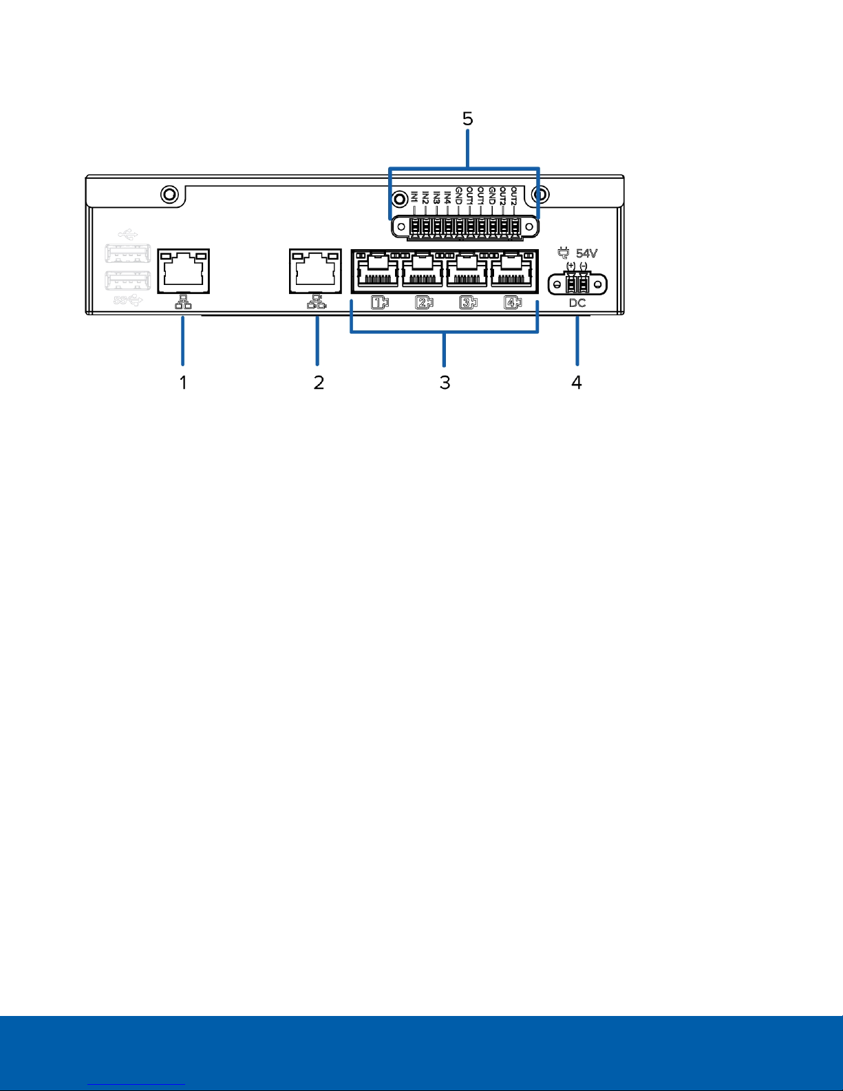
2. Connect an Ethernet cable directly from a DHCP enabled port on your configuring laptop to the camera
network port on the device.
3. Open a web browser on the connected laptop and enter this IP address: https://169.254.100.100.
If you cannot reach the IP address, see Troubleshooting — Cannot Reach Default IP Address on the next
page.
4. When you are prompted by the web interface, enter a new password for the administrator username.
The Strength meter measures the complexity of your password: Red is too simple, yellow is reasonably
complex, and green is complex. Complexity measures the difficulty to discover your password, not how
secure your password is. A complex password is recommended.
The page refreshes and you are prompted to log in.
5. Enter administrator as the username and your new password.
The Web Interface launch page is displayed.
6. In the navigation sidebar, expand ACC and click Server to open the ACC Server panel.
7. In the General pane, click the Client Installer Download button to download and install a copy of the
AvigilonControl Center (ACC) Client software to the connected laptop.
8. In the navigation sidebar, click Device to open the Device panel.
9. In the Hostname pane, assign a new hostname for the device.
10. In the navigation sidebar, click Network to open the Network panel.
11. In the Corporate and Camera panes, select how it obtains an IPaddress from the corporate network and
the camera network. For more information, see Network Panel on page20.
12. Connect an Ethernet cable from the device to the corporate network.
13. Disconnect the configuring laptop from the device.
14. If required, mount the device on a wall using the supplied mounting brackets.
CAUTION — The device must be mounted as instructed or any issues that arise will not be
covered by the warranty.
a. Attach the wall mount brackets to the lowest threaded holes on the sides of the device.
b. Position the device with the rear panel facing downwards.
c. Screw the wall mounting brackets to the wall.
Hardware Installation 4

15. Connect the cameras to the PoE switch component.
NOTE: Allow the device 1 to 2 minutes to budget power to all connected devices. The front camera
status LEDs initially show that PoE is provided to all connected devices, but the status may change if the
system detects that the total power consumption exceeds the PoE limits.
16. If required, connect other switches and cameras to the camera network.
Now, you can configure the device and cameras for daily operation through the Avigilon Control Center Client
software. For more information, see Configuring the Avigilon Control Center™ Software on page6.
Troubleshooting — Cannot Reach Default IP Address
If the 169.254.100.100 address is not accessible during the hardware installation, it is because the network cable
was connected to the corporate network port rather than the recommended camera port.
You can choose to restore the 169.254.100.100 address by reverting the appliance to its factory default settings.
For more information, see Restoring Factory Default Settings on page25.
Or, you can avoid reverting to the factory default settings by discovering the DHCP assigned IPaddress from the
ACC Client software:
1. Download and install the ACC Client software on to the configuration laptop.
The ACC Client software can be downloaded from the Avigilon website: avigilon.com.
2. Launch the ACC Client software.
3. Log into the site that uses this naming convention: VMA-RPA-4Px-xxxxxxxxxx.AVIGILON.
The default username is administrator, with no password.
NOTE: The username and password for the ACC application is separate from the credentials for the
appliance web interface. To change the password for the ACC application, see Changing the
Administrator Password on page7.
4. Display the server Setup tab.
At the top of the window, the appliance IP address is displayed.
5. Open a web browser and enter the IP address in this format: https://<IP address>.
6. Continue the remaining steps for installing the appliance.
Troubleshooting — Cannot Reach Default IP Address 5

Configuring the Avigilon Control Center™ Software
The ACC Client software allows you to view live and recorded video, monitor events, set up alarms, and control
user access to the system.
The ACC Client software is the application that you would use on a daily basis. It is also where most of the
system configurations are made.
This section includes the recommended steps for setting up your ACC system for the first time.
Starting Up and Shutting Down the Avigilon Control Center Client
Software
Starting Up the Client Software
Perform one of the following:
lIn the Start menu, select All Programs or All Apps > Avigilon > Avigilon Control Center Client.
lDouble-click or desktop shortcut icon.
lFrom the AvigilonControl Center Admin Tool, click Launch Control Center Client. For more information,
see the AvigilonControl Center Server User Guide.
When you are prompted, log in to your site. You can only access cameras and video after you log in.
Once the application has started, it will automatically display a list of all the sites that are connected to the same
network. You will be prompted to log in to all sites.
Shutting Down the Client Software
1. In the top-right corner of the Client software, select > Exit.
2. When the confirmation dialog box appears, click Yes.
Logging Into and Out of a Site
After you start the ACC Client software, you are immediately asked to log in to a site. By default, the ACC ES
Analytics Appliance is automatically added to the system as a server within a site of the same name.
Configuring the Avigilon Control Center™ Software 6

Logging In
1. Open the Site Login tab. The Site Login tab is automatically displayed if you are launching the Client
software for the first time.
To manually access the Site Login tab, do one of the following:
lFrom the top-right corner of the window, select > Log In….
lFrom the top-left corner of the application window, click to open the New Task menu, then
click .
2. On the left side of the Site Login tab, select one or more sites.
If the site you want to log into is not shown, click Find Site… to discover the site.
3. Enter your username and password for the selected sites.
4. Click Log In.
You are logged into the selected sites.
If you want to be notified when new or disconnected sites come online, select the Notify me when additional
sites become available check box.
If you want to see the login page each time you launch the Client software, select the Show this tab on startup
check box. If you prefer not to login each time, you can disable this option and configure automatic login from
the Client Settings dialog box.
Logging Out
You can log out of one or all sites at any time.
To... Do this...
Log out of one or select sites lIn the System Explorer, select one or more sites then right-click and
select Log Out.
Log out of all sites 1. In the top-right corner of the Client, select > Log Out.
2. In the confirmation dialog box, click Yes.
Changing the Administrator Password
After you log in to the ACC software for the first time, it is recommended that you change the default
administrator password.
Logging In 7

1. After you login, the Change Password dialog is displayed.
2. Enter a new password and then confirm the new password.
The password must meet the minimum strength requirements.
l— password meets the strength requirements.
l— password does not meet the strength requirements, enter a new password.
The password strength is defined by how easy it is for an unauthorized user to guess. If your password
does not meet the strength requirements, try entering a series of words that is easy for you to remember
but difficult for others to guess.
3. Click OK.
Tip: If you forget the default administrator password, resetting the password requires restoring the factory
default settings on every server in the site. To avoid this issue, it is highly recommended that you create at least
one other administrator level user as a backup.
Connecting Cameras to the Avigilon Control Center Software
After all the cameras in your system have been physically connected to the ACC ES Analytics Appliance, you
need to connect the cameras to the ACC software so that video can be recorded and indexed for search.
1. In the site Setup tab, click .
The Connect/Disconnect Devices… tab is displayed.
2. In the Discovered Devices area, select one or more devices then click Connect….
Tip: You can also drag the device to a server on the Connected Devices list.
3. In the Connect Device dialog box, select the server you want the device to connect to.
NOTE: If you are connecting multiple devices, all the cameras must use the same connection settings.
4. If you are connecting a third-party device, you may choose to connect the device by its native driver. In
the Device Type: drop-down list, select the device's brand name. If there is only one option in the drop-
down list, the system only supports one type of driver from the device.
5. In the Connection Type: drop-down list, select Primary. The device will automatically connect to this
server if they are in the same network.
If you are creating a failover connection, select Secondary or Tertiary.
6. In the License Priority: drop-down list, select the appropriate license priority. The highest priority is 1and
the lowest priority is 5.
NOTE: This option is only available if you are connecting to a Secondary or Tertiary server.
Connecting Cameras to the Avigilon Control Center Software 8

The License Priority: setting decides the order that devices are connected to the server. The server will
try to connect cameras with a higher priority before cameras with lower priority. If the server does not
have enough camera channel licenses, low priority devices may not be connected. A camera channel
license is only used when the device actually connects to the server.
7. If the camera supports a secure connection, the Device Control: drop-down list is displayed. Select one
of the following options:
NOTE: The setting may not be displayed if the camera only supports one of the options.
lSecure — The system will protect and secure the camera's configuration and login details. This
option is selected by default.
lUnsecure — The camera's configuration and login details will not be secured and may be
accessible to users with unauthorized access.
Cameras with a secure connection are identified with the icon in the Status column.
8. If it is not displayed, click to display the Site View Editor and choose where the device appears in the
System Explorer.
lIn the site directory, drag devices up and down the right pane to set where it is displayed.
lIf your site includes folders, select a location for the device in the left pane. The right pane
updates to show what is stored in that directory.
lIf you are connecting multiple devices at the same time, the selected devices must be assigned to
the same location.
Tip: If the site you want is not listed, you may need to connect the device to a different server. Make sure
the selected server is connected to the site you want.
9. Click OK.
10. If the device is password protected, the Device Authentication dialog box appears. Enter the device's
username and password, then click OK.
Setting the Recording Schedule
Once all the cameras have been connected, you can set when you want each camera to record video.
By default, all connected cameras are set to record when events are detected by the system. You can skip this
procedure if you prefer to keep the default settings.
Before you can assign a recording schedule, you must create a template. The template allows you to assign the
same schedule to multiple cameras.
Creating a Recording Template
The events that can be selected for the template depend on the licensed features in your system.
NOTE: Be aware that the system recording schedules use the same timezone as the appliance. For more
information about setting the time, see Device Panel on page18.
Setting the Recording Schedule 9

1. In the server Setup tab, click . The Recording Schedule dialog box is displayed.
2. Click Add Template below the Templates: list.
3. Enter a name for the New Template.
4. Click the Set Area button, then click or drag the cursor across the Recording Mode: timeline to set the
types of events that the cameras will record throughout the day. Individual rectangles on the Recording
Mode: timeline are colored when they have been selected.
The Recording Mode: options include:
lContinuous — record video constantly.
lMotion — only record video when motion is detected.
lDigital Inputs — only record video when a digital input is activated.
lAlarms — only record video when an alarm is activated.
5. To disable recording in parts of the template, click the Clear Area button, then click or drag the cursor
across the timeline to remove the set recording areas.
6. If cameras are not recording in Continuous mode all day, you can set cameras to record reference
images between events in the recording schedule.
lSelect the Record a reference image every: check box, then set the time between each reference
image.
Setting Up a Weekly Recording Schedule
You can set up a weekly recording schedule by applying templates to cameras for each day of the week.
1. In the server Setup tab, click . The Recording Schedule dialog box is displayed.
2. Select a template from the Templates: list.
3. In the Default Week area, click the days of the week this template applies to for each camera.
Figure 1: The Recording Schedule dialog box: Default Week
4. Click OK.
Setting Data Aging
Data aging defines how long recorded video is stored and the quality of the video as it ages over time. In the
ACC software, the recorded image rate is slowly reduced so that recorded video can be viewed over a longer
period of time while still making room for new recordings. You can adjust how long the full image rate video is
kept, so that you have the best quality video when you need it.
Setting Up a Weekly Recording Schedule 10

The amount of data aging that is available depends on the camera you have connected to your system:
lFor JPEG2000 or JPEG compression cameras, data aging is available at three rates:
lHigh Bandwidth keeps recordings at their original quality.
lHalf Image Rate discards half of the recorded data to make room for new recordings.
lQuarter Image Rate keeps 1/4 of the original recorded data so that you can still see older video.
lFor H.264 cameras that support data aging, data aging is available at two rates:
lHigh Bandwidth keeps the original high quality video and the secondary stream of low resolution
video.
lLow Bandwidth only keeps the secondary stream of low resolution video.
NOTE: The data aging can only occur when the secondary stream is enabled.
lFor H.264 cameras that do not support data aging, only the High Bandwidth video is kept.
By default, the system is set to keep recorded video for the maximum amount of time based on the available
storage.
At the bottom of the Recording and Bandwidth dialog is the following statement:
Total record time estimate is based on constant recording
The retention time is determined by the Max. Record Time setting and the average camera data rate. Since the
system can only provide an estimate of the data rate for the full retention period, the actual retention time may
exceed the Max. Record Time setting by 5 minutes.
NOTE: The time shown in the Total Record Time column is an estimate only.
1. In the server Setup tab, click .
The Recording and Bandwidth dialog box is displayed.
The Data Aging column shows an estimate of the recording time that is available at each image rate,
given the amount of space on the recording device.
2. In the Data Aging column, move the sliders to adjust the amount of time video is stored at each image
rate.
lTo change the data aging settings for all linked cameras, move the slider for one linked camera
and all linked cameras will be updated.
lTo change the data aging setting for one camera, break the camera's link to other cameras by
clicking the icon to the left of its name, then make your changes.
3. In the Max. Record Time column, manually enter a maximum record time or select one of the options from
the drop-down list for each camera.
NOTE: If the time estimated in the Total Record Time column is significantly shorter than what is set in the
Max. Record Time column, the camera's actual recording time will be closer to the Total Record Time
estimate.
4. Click OK.
Setting Data Aging 11

Enabling Server Analytics
You can enable the system to detect classified objects using self-learning video analytics on any non-analytics
camera connected to the appliance.
Be aware that there is a limit to the system's analytic capacity. Refer to the Total Analytic Load bar to avoid
exceeding the system's analytic capacity.
NOTE: The Avigilon ACC ES Analytics Appliance does not currently support unusual motion detection.
1. In the server Setup tab, click .
2. In the following dialog box, a list of connected cameras are displayed.
Only cameras without video analytics capabilities are displayed.
If you do not have access rights for a camera, it will not be shown in this list.
3. To enable video analytics, select the check box beside the connected camera.
The Total Analytic Load bar displays the appliance's video analytics capacity. The percentage is based
on the enabled camera's current Compression and Image Rate settings.
4. Click OK.
Your settings are now saved.
Adding Users and Groups
If there will be other people using the system, you may want to add them as separate users rather than giving
them access through the default administrator account.
Before you can add individual users, you will need to add permission groups that define what users have access
to. By default, the system has the following groups:
lAdministrators — has access to everything in the system.
lPower Users — has access to most features in the system except for the ability to import and export
settings.
lRestricted Users — has access to live video only and can control audio and digital outputs.
lStandard Users — has access to live and recorded video, but cannot make any Setup changes.
It is highly recommended that the Administrators group includes at least two users. In the event one
administrator user forgets the default administrator password, the second administrator user can be used to
reset the password. If you do not have a second administrator user, you may need to completely reset the
system.
Enabling Server Analytics 12

Adding Groups
1. In the site Setup tab, click .
2. In the following dialog box, select the Groups tab and click Add Group.
3. In the pop-up dialog box, select an existing group to use as a template for your new group, then click OK.
4. In the Edit Group dialog box, complete the following:
a. Give the new group a name.
b. Select a rank for the group from the Rank: drop-down list. To edit or view the entire Corporate
Hierarchy, click .
c. Move the Min Password Strength: slider to define how strong the password used by each user in
the group must be.
The password strength is defined by an algorithm that anticipates how easy a password is to
guess. There is no defined character minimum, but the stronger the setting, the harder it should be
for an unauthorized user to crack the password.
Tip: If users are expected to change their passwords frequently, you may want to select a weaker
setting to ensure users do not have difficulty choosing new passwords.
d. Select the required Group Privileges: and Access Rights: for the group. Clear the check box of any
feature or device that you do not want the group to have access to.
5. Click Edit Groups to enable the Dual Authorization feature.
When you enable Dual Authorization, users in this group cannot review recorded video without
permission from a user in the authorizing group.
a. In the following dialog box, select the groups that can grant authorization to users in this group.
b. To disable the feature, click the toggle at the top of the dialog box.
c. Click OK.
6. Select the Members tab to add users to the group.
If a user is added to the group through the Add/Edit User dialog box, the user is automatically added to
the group's Members list.
a. Click .
b. Select the users that should be part of this new group. Only users that have been added to the site
are displayed.
Tip: Enter the name of a user in the Search… field to locate specific users.
c. Click Add. The users are added to the Members list.
7. Click OK to save the new group.
Adding Groups 13

Adding Users
1. In the site Setup tab, click .
2. In the Users tab, click Add User.
3. When the Add/Edit User dialog box appears, complete the User Information area.
4. If you don’t want this user to be active yet, select the Disable user check box. Disabled users are in the
system but cannot access the site.
5. In the Login Timeout area, select the Enable login timeout check box to set the maximum amount of time
the Avigilon Control Center Client software can be idle before the user is automatically logged out of the
application.
6. Select the Member Of tab to assign the user to a group.
a. Select the check box beside each access group the user belongs to.
The other columns display the permissions that are included in the selected groups.
b. Return to the General tab.
7. In the Password area, complete the following fields:
lPassword: — enter a password for the user.
lConfirm Password: — re-enter the password.
lStrength: — indicates the strength of the password. The strength is defined by the group the user
is assigned to. If the user is a member of more than one group, the user must meet the strongest
password requirement.
The password must meet the minimum strength requirements.
l— password meets the strength requirements.
l— password does not meet the strength requirements, enter a new password.
The password strength is defined by how easy it is for an unauthorized user to guess. If your
password does not meet the strength requirements, try entering a series of words that is easy for
you to remember but difficult for others to guess.
lRequire password change on next login — select this check box if the user must replace the
password after the first login.
lPassword Expiry (Days): — specify the number of days before the password must be changed.
lPassword never expires — select thischeck box if the password never needs to be changed.
8. Click OK. The user is added to the site.
Repeat this procedure to add all the users that are required.
Advanced Settings
The following list include some advanced settings that you can use to further customize your system. See the
application Help files for details about how to configure these settings.
Adding Users 14

lAdjust camera settings
lIf camera video looks slightly blurry or unclear, you can adjust the camera's Image and Display
settings.
lIf you want the camera to record at a different image rate, you can adjust the camera's
Compression and Image Rate settings.
NOTE: For optimal analytics performance, the source camera should stream a minimum of 10
images per second (ips).
lTo reduce the amount of ambient motion detection for a specific camera, you can adjust the
Motion Detection settings.
lTo maintain the privacy of certain areas, you can set Privacy Zones in the camera's field of view so
that private spaces are never recorded.
lClassified object detection
lAvailable to cameras that have server-side analytics enabled, and available to other Avigilon
video analytics cameras.
lUse the Analytic Events dialog box to configure classified object motion detection. Once
configured, you can receive events, trigger alarms, define rules, and record video when specific
object motion requires your attention.
lAlarms
lUse the Alarms dialog box to create and manage alarms. Once an alarm has been created, you can
monitor alarm events in the Alarms tab and in the Avigilon Control Center Mobile App.
lConfigure digital inputs and outputs
lThe digital I/O connector on the appliance can be configured as an independent digital I/O device.
lUse the Digital Inputs and Outputs dialog box to configure the appliance's I/O settings. Once
configured, you can use the digital inputs and outputs in alarms and other system actions.
lEmail notifications
lYou can set up an SMTP email server to send you messages when system events occur.
lSetup the Gateway
lThe ACC Gateway software allows you to access video from a remote web browser or mobile
device. If the Gateway software is not set up, you cannot access video outside of your local
network.
lInstall the ACC Mobile app on your mobile device so that you can remotely monitor live and
recorded video.
Advanced Settings 15

Configuring the Appliance
The ACC ES Analytics Appliance can be configured through a web interface that is accessible from any browser
on the network. The web interface allows you to configure the appliance server settings like the AvigilonControl
Center Admin Tool.
The web interface allows you to configure the network settings, set how the system keeps time, and allows you
to remotely restart or upgrade the system.
Accessing the Web Interface
During the installation process, you connected a laptop directly to the device and used a special IP address to
access the web interface. After the device has been set up and is connected to the corporate network, you can
access the web interface following these steps:
1. On a computer with network access to the device enter the IP address of the device into a web browser:
https://<Device IP address >/
For example: https://192.168.1.40/
Tip: If you forgot the IPaddress that was configured during the installation process, the device IP address
is listed in the ACC Client software, in the server Setup tab.
2. When you are prompted, enter the web interface username and password.
The username is always administrator. Use the password you configured when you logged in to the
device for the first time. For more information, see Hardware Installation on page4.
Web Interface Launch Page
The Web Interface launch page consists of a Dashboard navigation bar and five panes displaying status
information:
lACC Server: Displays Running when the ACC Server software is operating; otherwise it displays Stopped.
The panel provides technical information about the device:site name, server name, server ID,server
version, software version, the number of available camera channels, and the maximum number of ACC
client instances allowed.
lSystem: Displays Ready when the device is fully operational, and Rebooting then Initializing when the
device is restarting. The panel provides technical information about your device:product name, part
number, serial number, and firmware version.
lStorage: Displays the storage capacity of the device and the status of the storage disks.
lNetwork—Displays information about the two uplink ports on the device. Click to open the Network
Panel.
lPoE—Displays status information about each PoE port. Icons in the panel let you quickly see how many
ports are in use, their status, speed and whether the link is up or down. Click to open the Device Panel.
Configuring the Appliance 16
Other manuals for ACC VMA-RPA-4P2
2
This manual suits for next models
1
Table of contents
Other Avigilon Server manuals