Avital 2000 User manual

Model 2000
Installation Guide
© 2001 Directed Electronics, Inc. Vista, CA N2000 8-01
Rev. N/C 1.0

2© 2001 Directed Electronics, Inc. Vista, CA
table of contents
Bitwriter™, Code Hopping™, DEI®, Doubleguard®, ESP™, FailSafe®, Ghost Switch™, Learn Routine™, Nite-
Lite®, Nuisance Prevention Circuitry®, NPC®, Revenger®, Silent Mode™, Soft Chirp®, Stinger®, Valet®,
Vehicle Recovery System®, VRS®, and Warn Away®are all Trademarks or Registered Trademarks of
Directed Electronics, Inc.
what is included
■The control module
■Two 2-button remote transmitters
■The plug-in status LED
■The plug-in Valet/program switch
■The 12-pin primary harness
■The 6-pin door lock harness
■The 2-pin starter kill harness
■The owner’s guide
■The installation guide
What Is Included . . . . . . . . . . . . . . . . . . . . . 2
Primary Harness (H1), 12-Pin Connector . . . . . 3
Door Lock Harness (H2), 6-Pin Connector . . . . 3
Starter Kill Harness (H3), 2-Pin Connector . . . 4
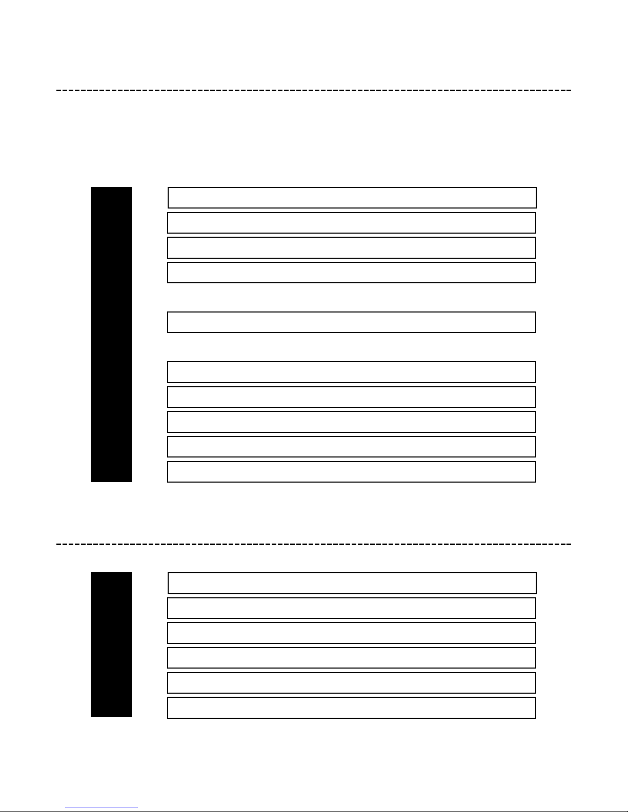
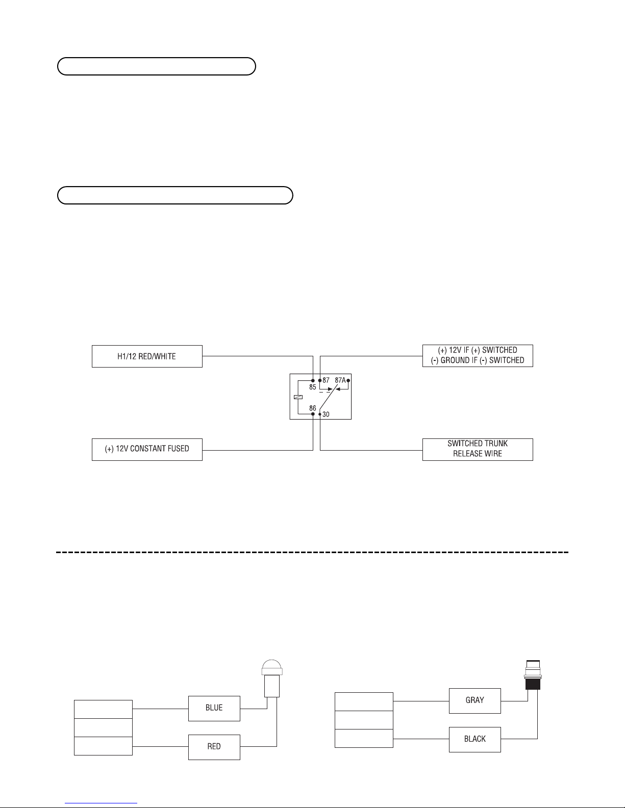
Primary Harness (H1) Wire Connection Guide. . 4
Plug-In LED and Valet/Program Switch. . . . . . . 7
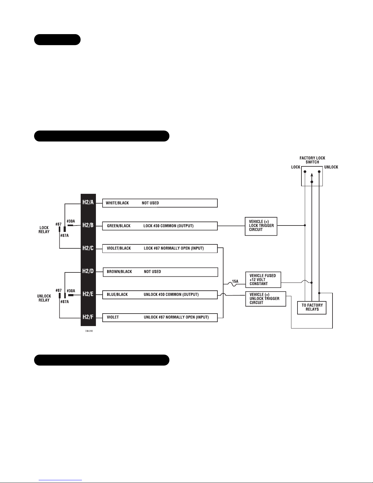
Door Lock Harness (H2) Wire Connection Guide. . 8
Identifying the Door Lock System . . . . . . . . 8
At the Switch . . . . . . . . . . . . . . . . . . . . . 9
Type A Door Locks: Positive-Triggered,
Relay Driven System . . . . . . . . . . . . . . . . . 9
Type B Door Locks: Negative-Triggered,
Relay Driven System . . . . . . . . . . . . . . . . . 9
Testing Reversing Polarity Systems . . . . . . . 10
Type C Door Locks: Reversing Polarity System. 11
Type D Door Locks: Adding One or More
After-Market Actuators . . . . . . . . . . . . . . . 12
Type E Door Locks: Electrically-Activated
Vacuum. . . . . . . . . . . . . . . . . . . . . . . . . 13
Type F Door Locks: One-Wire System
(Cut to Lock, Ground to Unlock) . . . . . . . . 14
Type G Door Locks: Positive Multiplex . . . . . 14
Type H Door Locks: Negative Multiplex . . . . 15
Type A Progressive Door Unlock . . . . . . . . 17
Type B Progressive Door Unlock . . . . . . . . . 18
Starter Kill Harness (H3)
Wire Connection Guide . . . . . . . . . . . . . . . . 18
Transmitter/Receiver Learn Routine. . . . . . . . 19
To Advance From One Channel to Another . . 20
To Exit Learn Routine . . . . . . . . . . . . . . . 20
Transmitter Configuration . . . . . . . . . . . . . . 20
Operating Settings Learn Routine . . . . . . . . . 21
To Access Another Feature . . . . . . . . . . . . 22
To Exit the Learn Routine . . . . . . . . . . . . . 22
Features Menu . . . . . . . . . . . . . . . . . . . . . . 22
Feature Descriptions . . . . . . . . . . . . . . . . . . 23
Troubleshooting . . . . . . . . . . . . . . . . . . . . . 23
Wiring Quick Reference Guide . . . . . . . . . . . 24

© 2001 Directed Electronics, Inc. Vista, CA 3
primary harness (H1), 12-pin connector
The primary harness is the standard 12-pin harness used by DEI security systems. Two pins in the harness do not
have wires (H1/5 and H1/7). The functions of all the wires that are used in the primary harness are outlined in
this section. The wire connections are described in the Primary Harness (H1) Wire Connection Guide section.
______
______
______
______
______
______
______
______
______
______
door lock harness (H2), 6-pin connector
______
______
______
______
______
______
*NOTE: VIOLET and VIOLET/BLACK are common at the fuse holder.
VIOLET* UNLOCK #87 NORMALLY OPEN (INPUT)
BLUE/BLACK UNLOCK #30 COMMON (OUTPUT)
BROWN/BLACK UNLOCK #87A NORMALLY CLOSED
VIOLET/BLACK* LOCK #87 NORMALLY OPEN (INPUT)
GREEN/BLACK LOCK #30 COMMON (OUTPUT)
WHITE/BLACK LOCK #87A NORMALLY CLOSED
H2/A
H2/B
H2/C
H2/D
H2/E
H2/F
RED/WHITE (-) 200 mA CHANNEL 2 VALIDITY OUTPUT
RED (+)12V CONSTANT POWER INPUT
BROWN (-) HORN HONK OUTPUT
YELLOW (+) SWITCHED IGNITION INPUT
BLACK (-) CHASSIS GROUND INPUT
BLUE (-) 200 mA SECOND UNLOCK OUTPUT
BLACK/WHITE (-) 200 mA DOMELIGHT SUPERVISION OUTPUT
WHITE/BLUE (-) 200 mA CHANNEL 3 VALIDITY OUTPUT
WHITE (+) LIGHT FLASH OUTPUT
ORANGE (-) 500 mA GROUND-WHEN-ARMED OUTPUT
H1/1
H1/2
H1/3
H1/4
H1/5
H1/6
H1/7
H1/8
H1/9
H1/10
H1/11
H1/12

4© 2001 Directed Electronics, Inc. Vista, CA
starter kill harness (H3), 2-pin connector
______
______
primary harness (H1) wire connection guide
This wire supplies (-) ground as long as the system is armed. This output ceases as soon as the system is dis-
armed. This wire can be used to turn on an optional sensor or to ready an optional accessory, such as a pager module.
This wire should be connected to the (+) parking light wire. This output is protected with a 10 amp fuse. Never
increase the value of the light flash fuse. If more current is required, use an external relay.
NOTE: When connecting this wire to a (-) parking light wire, a relay is required. See the following
diagram for the relay application.
H1/2 WHITE (+) light flash output
H1/1 ORANGE (-) ground-when-armed output
BLACK STARTER KILL OUTPUT
BLACK STARTER KILL INPUT
H3/1
H3/2

© 2001 Directed Electronics, Inc. Vista, CA 5
This wire provides a (-) 200 mA output whenever the transmitter code controlling Channel 3 is received. This
output will continue as long as that transmission is received. Use for options such as 551T Valet® Start system,
529T or 530T power window controllers, etc.
IMPORTANT! Never use this wire to drive anything except a relay or a low-current input! The tran-
sistorized output can only provide 200 mA of current, and connecting directly to a solenoid, motor,
or other high-current device will cause it to fail.
Connect this wire to the optional domelight supervision relay as shown below:
IMPORTANT! This output is only intended to drive a relay. It cannot be connected directly to the
domelight circuit, because the output cannot support the current draw of one or more light bulbs.
This output is used for progressive door unlock. A progressive unlock system unlocks the driver's door when the
unlock (disarm) button is pressed and unlocks the passenger doors if the unlock (disarm) button is pressed again
within 15 seconds after unlocking the driver's door. The BLUE wire outputs a low current (-) pulse on the second
press of the unlock button of the transmitter. This negative unlock output is used to unlock the passenger doors.
Please refer to the Type A Progressive Door Unlock and Type B Progressive Door Unlock diagrams in the Door Lock
Harness (H2) Wire Connection Guide section of this manual.
Connect the H1/8 BLACK wire to bare metal, preferably with a factory bolt rather than your own screw (screws
tend to either strip or loosen with time). We recommend grounding all your components to the same point in
the vehicle.
H1/8 BLACK (-) chassis ground connection
H1/6 BLUE (-) 200mA second unlock output
H1/4 BLACK/WHITE (-) domelight supervision relay output
H1/3 WHITE/BLUE (-) channel 3 output

6© 2001 Directed Electronics, Inc. Vista, CA
Connect this wire to an ignition source. This input must show (+)12V with the key in run position and during
cranking. Make sure that this wire cannot be shorted to the chassis at any point. This wire will trigger the system
if the ignition is turned on before the unit is disarmed (doors unlocked with the remote). It will also honk the
vehicle’s horn and flash the parking lights (if connected).
NOTE: Feature 4 (Security Features) must be turned on in order for this wire to trigger the system.
See Features Menu section of this guide.
This wire supplies a (-) 200 mA output that can be used to honk the vehicle horn. It outputs a single pulse to
confirm that the doors are locked if the lock button on the remote is pressed more than once. It also outputs
two pulses to confirm that the doors are unlocked if the unlock button on the remote is pressed more than two
times. This wire also outputs pulses for 30 seconds whenever the Panic Mode is activated. If the vehicle has a
(+) horn circuit, an outboard relay can be used to interface with the system, as shown in the following diagram.
H1/10 BROWN (-) horn honk output
H1/9 YELLOW (+) ignition input

© 2001 Directed Electronics, Inc. Vista, CA 7
Before connecting this wire, remove the supplied fuse. Connect to the positive battery terminal or the constant
12V supply to the ignition switch.
NOTE: Always use a fuse within 12 inches of the point you obtain (+)12V power. Do not use the
15A fuse in the harness for this purpose. This fuse protects the module itself.
When the system receives the transmitter code controlling Channel 2 for longer than 1.5 seconds, the red/white
wire will supply an output as long as the transmission continues. This is often used to operate a trunk/hatch
release or other relay-driven functions.
IMPORTANT! Never use this wire to drive anything but a relay or a low-current input! The transis-
torized output can only supply 200 mA of current. Connecting directly to a solenoid, motor, or other
high-current device will cause it to fail.
plug-in LED and valet/program switch
The LED and the Valet/Program switch both plug into the control module. The status LED plugs into the white
two-pin port, while the Valet®/Program switch should be plugged into the blue two-pin port. The status LED and
Valet®/Program switch each fit into 9/32-inch holes.
Status LED Valet®/Program Switch
H1/12 RED/WHITE channel 2, (-) 200mA output
H1/11 RED (+)12V constant power input

8© 2001 Directed Electronics, Inc. Vista, CA
door lock harness (H2) wire connection guide
The system has door lock relays on-board, and can directly interface with most electric power door lock systems
drawing 30 amps or less. It can also drive aftermarket actuators directly. (Some vehicles require that an after-
market actuator be added to the driver’s door to allow system control, see Type D wiring section).
The easiest way to determine which type of door lock system you are working with is to remove the master
locking switch itself, which is usually on the driver’s door or on the center console. Once you have determined
which type of factory door lock circuit you are working with, and the color codes of the switch wires to be used,
you can usually simplify the installation by locating the same wires in the vehicle’s kick panel. If no central
locking switch is found, the installation may require a door lock actuator.
NOTE: Always retest the wires in the kick panel to be sure they function the same way as the wires
on the switch.
There are eight common types of door lock circuits (some vehicles use more unusual systems):
■Type A: Three-wire (+) pulse controlling factory lock relays. Most GM, some Ford and Chrysler, 1995 Saturn,
some new VW, newer BMW.
■Type B: Three-wire (-) pulse controlling factory lock relays. Most Asian vehicles, early Saturn, some BMW and
Porsche.
■Type C: Directly-wired reversing-polarity switches. The switches are wired directly to the motors. This type
of system has no factory relays. Most Fords, many GM two-doors cars and trucks, many Chryslers.
■Type D: Adding one or more aftermarket actuators. These include slave systems without an actuator in the
driver’s door, but with factory actuators in all the other doors. Type D also includes cars without power locks,
which will have actuators added. All Saabs before 1994, all Volvo except 850i, all Subaru, most Isuzu, and
many Mazdas. Some mid-eighties Nissans, pre-1985 Mercedes-Benz and Audi.
■Type E: Electrically-activated vacuum systems. The vehicle must have a vacuum actuator in each door. Make
sure that locking the doors from the driver's or passenger side using the key activates all the actuators in
the vehicle. This requires a slight modification to the door lock harness. Mercedes-Benz and Audi 1985 and
newer.
■Type F: One-wire system - cut to lock, ground to unlock. This system is found in late-model Nissan Sentras,
some Nissan 240SX, and Nissan 300ZX 1992 and later. It is also found in older Mitsubishis, and some early
Mazda MPV’s.
■Type G: Positive (+) multiplex. This system is most commonly found in Ford, Mazda, Chrysler and GM vehi-
cles.
■Type H: Negative (-) multiplex. The system is most commonly found in Ford, Mazda, Chrysler and GM vehi-
cles. The door lock switch or door key cylinder may contain either one or two resistors.
identifying the door lock system

© 2001 Directed Electronics, Inc. Vista, CA 9
■Three-wire switches will have either a constant ground input or a constant (+)12V input, along with the
pulsed lock and unlock outputs to the factory relays.
■Many BMW’s and VW’s have no external switch. The switches are inside the actuator, and instead of pulsing,
the proper wires will flip-flop from (+)12V to (-) ground as the door locks are operated.
■Direct-wired switches will have a (+)12V constant input and one or two (-) ground inputs, along with two
output leads going directly to the lock motors.
This system is common in many Toyota, Nissan, Honda, and Saturn models, as well as Fords with the keyless-
entry system (some other Fords also use Type B).
The switch will have three wires on it, and one wire will test ground all the time. One wire will pulse (-) when
the switch locks the doors, and the other wire will pulse (-) when the switch unlocks the doors. This type of
system is difficult to mistake for any other type.
type B: negative-triggered, relay-driven system
type A: positive-triggered, relay-driven system
at the switch

10 © 2001 Directed Electronics, Inc. Vista, CA
Use these instructions if the power door lock switch has four or five heavy-gauge wires. This type of switch has
two outputs that rest at (-) ground.
IMPORTANT! To interface with these systems, you must cut two switch leads. The relays must dupli-
cate the factory door lock switches’ operation. The master switch will have one or two ground inputs,
one (+)12V input, and two switch outputs going directly to the slave switch and through to the
motors. These outputs rest at (-) ground. The lock or unlock wire is switched to (+)12V, while the
other wire is still grounded, thus completing the circuit and powering the motor. This will discon-
nect the switch from the motor before supplying the motor with (+)12V, avoiding sending (+)12V
directly to (-) ground.
It is critical to identify the proper wires and locate the master switch to interface properly. Locate wires that
show voltage when the switch is moved to the lock or unlock position. Cut one of the suspect wires and check
operation of the locks from both switches. If one switch loses all operation in both directions then you have cut
one of the correct wires and the switch that is entirely dead is the master switch. If both switches still operate
in any way and one or more door motors have stopped responding entirely, you have cut a motor lead. Reconnect
it and continue to test for another wire. Once both wires have been located and the master switch identified, cut
both wires and interface as described in the following paragraphs.
WARNING! If these wires are not connected properly, you will send (+)12V directly to (-) ground,
possibly damaging the system or the factory switch.
testing reversing polarity systems

© 2001 Directed Electronics, Inc. Vista, CA 11
■H2/A WHITE/BLACK: Once both door lock wires are located and cut, connect the white/black wire to the
master switch side of the lock wire. The master switch side will show (+)12V when the master switch is oper-
ated to the lock position and (-) ground when the master switch is in the middle position.
■H2/B GREEN/BLACK: Connect the green/black wire to the other side of the lock wire. This is the motor side
of the lock wire and it goes to the lock motor through the slave switch.
■H2/C VIOLET/BLACK: This wire must be connected to a constant (+)12 volts. The best connection point for
this wire is the constant (+)12V supply for the door lock switch*, or directly to the positive (+) battery post
with a fuse at the battery post.
*NOTE: Except in GM cars with retained accessory power (RAP). In these vehicles, the (+)12V feed
to the door lock switches is turned off if the doors are closed for any length of time.
NOTE: Most direct-wired power lock systems require 15 amps of current to operate. Connecting the
violet/black wire to a poor source of voltage will keep the door locks from operating properly.
■H2/D BROWN/BLACK: Connect the brown/black wire to the master switch side of the unlock wire. The master
switch side will show (+)12V when the master switch is in the unlock position and (-) ground when the
master switch is in the middle position.
■H2/E BLUE/BLACK: Connect the blue/black wire to the other side of the unlock wire.
type C: reversing polarity system

12 © 2001 Directed Electronics, Inc. Vista, CA
Vehicles without factory power door locks require the installation of one actuator per door. This requires mount-
ing the door lock actuator inside the door. Other vehicles may only require one actuator installed in the driver's
door if all door locks are operated when the driver's lock is used.
type D: adding one or more after-market actuators

© 2001 Directed Electronics, Inc. Vista, CA 13
This system is found in Mercedes-Benz and Audi 1985 and newer. The door locks are controlled by an electrically
activated vacuum pump. The control wire will show (+)12V when doors are unlocked and (-) ground when locked.
NOTE: The system must be programmed for 3.5-second door lock pulses, and the violet jumper
between the #87 lock terminal and the #87 unlock terminal must be cut.
type E: electrically-activated vacuum

14 © 2001 Directed Electronics, Inc. Vista, CA
This type of door lock system usually requires a negative pulse to unlock, and cutting the wire to lock the door.
(With some vehicles, these are reversed.) It is found in the late-model Nissan Sentras, some Nissan 240SX, Nissan
300ZX 1992 and later. It is also found in some Mazda MPV's.
NOTE: The violet jumper between the #87 lock terminal and the #87 unlock terminal must be cut.
This system is most commonly found in Ford, Mazda, Chrysler and GM vehicles. The door lock switch or door key
cylinder may contain either one or two resistors.
SINGLE-RESISTOR TYPE: If one resistor is used in the door lock switch/key cylinder, the wire will pulse (+)12V in
one direction and less than (+)12V when operated in the opposite direction.
TWO-RESISTOR TYPE: If two resistors are used in the factory door lock switch/key cylinder, the switch/key cylin-
der will read less than (+)12V in both directions.
DETERMINING THE PROPER RESISTOR VALUES: To determine the resistor values, the door lock switch/key cylinder
must be isolated from the factory door lock system. For testing, use a calibrated digital multimeter that is set to ohms.
IMPORTANT: To ensure an accurate resistance reading, do not touch the resistor or leads during testing.
type G: positive (+) multiplex
type F: one-wire system (cut to lock, ground to unlock)

© 2001 Directed Electronics, Inc. Vista, CA 15
1. Cut the output wire from the door lock switch/key cylinder in half.
2. Test with the meter from the switch side of the cut door lock switch/key cylinder wire to a reliable constant
(+)12V source. Some good constant (+)12V references are the power input source to the door lock switch/key
cylinder, the ignition switch power wire, or the (+) terminal of the battery.
3. Operate the door lock switch/key cylinder in both directions to determine the resistor values. If the multi-
meter displays zero resistance in one direction, no resistor is needed for that direction.
4. Once the resistor value(s) is determined, refer to the wiring diagram for proper wiring.
The system is most commonly found in Ford, Mazda, Chrysler and GM vehicles. The door lock switch or door key
cylinder may contain either one or two resistors.
SINGLE-RESISTOR TYPE: If one resistor is used in the door lock switch/key cylinder, the wire will pulse ground
in one direction and resistance to ground when operated in the opposite direction.
TWO-RESISTOR TYPE: If two resistors are used in the factory door lock switch/key cylinder, the door lock
switch/key cylinder will read resistance to ground in both directions.
DETERMINING THE PROPER RESISTOR VALUES: To determine the resistor values, the door lock switch/key cylinder
must be isolated from the factory door lock system. For testing, use a calibrated digital multimeter that is set to ohms.
IMPORTANT: To ensure an accurate resistance reading, do not touch the resistor or leads during testing.
type H: negative (-) multiplex

16 © 2001 Directed Electronics, Inc. Vista, CA
1. Cut the output wire from the door lock switch/key cylinder in half.
2. Test with the meter from the switch side of the cut door lock switch/key cylinder wire to a reliable ground
source. Some good ground references are the ground input source to the door lock switch/key cylinder or the
battery ground.
3. Operate the door lock switch/key cylinder in both directions to determine the resistor values. If the multi-
meter displays zero resistance in one direction, no resistor is needed for that direction.
4. Once the resistor value(s) is determined, refer to the wiring diagram for proper wiring.

© 2001 Directed Electronics, Inc. Vista, CA 17
type A progressive door unlock

18 © 2001 Directed Electronics, Inc. Vista, CA
starter kill harness (H3) wire connection guide
Use one of these wires as a starter kill input and the other as a starter kill output wire (they are interchangeable).
H3/1 and H3/2 BLACK starter kill wires
type B progressive door unlock

© 2001 Directed Electronics, Inc. Vista, CA 19
transmitter/receiver learn routine™
Transmitters are taught to the system using the Learn Routine. This system will learn up to four transmitters.
Both transmitters are factory programmed using for arm/panic on; for disarm/panic off/Channel Two;
and Buttons and together operate Channel Three. This configuration can be changed or new remotes
can be added to the system using the Learn Routine.
1. Key. Turn the ignition to the run position. (The YELLOW H1/9 wire must be already be con-
nected.)
2. Valet®/Program switch. Press and release the Valet®/Program switch the correct number of
times corresponding to the desired channel number (see chart below). Then press the
Valet/Program switch once more and HOLD it. The LED will blink to indicate the selected
channel and the horn will honk (if connected). Do not release the Valet/Program switch.
Pressing the Valet/Program Switch five times will delete all transmitters that are pro-
grammed into the system and will also change the operating settings back to the default
settings (see Operating Settings Learn Routine section of this guide). To use this option, select
Channel 5 (LED will blink five times) then transmit from any button of a known remote.
3. Transmit. While HOLDING the Valet®/Program switch, press the button on the transmit-
ter that you would like to control the selected receiver channel. One honk will confirm that
the code has been learned.
NOTE: For Channel 4, press to program the Auto Learn Standard Configuration on the two-
button transmitter.
CHANNEL PRESS AND RELEASE
NUMBER THE VALET/PROGRAM SWITCH TO PROGRAM FUNCTION
1 One time Arm/Panic
2 Two times Disarm/Channel 2
3 Three times Channel 3
4 Four times Auto Learn Standard Configuration*
5 Five times Delete all transmitters
*NOTE: For the Auto Learn Standard Configuration, see the Transmitter Configuration
section of this guide.

20 © 2001 Directed Electronics, Inc. Vista, CA
4. Release. Once the code is learned, the Valet/Program switch can be released.
You can advance from one channel to another by releasing the Valet®/Program switch and tapping it to advance
channels and then HOLDING it. For instance: You have programmed Channel 1 and you want to program Channel
2. Release the Valet®/Program switch. Press it one time and release it to advance from Channel 1 to Channel 2.
Now, press and HOLD the Valet/Program switch down and the unit will chirp twice. As before, do not release it.
If you want to program Channel 3 after programming Channel 1, release the Valet/Program switch, press it twice
and then release it to advance to Channel 3. Then press the Valet/Program switch once more and HOLD it. The
horn will honk three times to confirm it is ready to receive the code from the transmitter to program Channel 3.
One long horn honk (if connected) indicates that the learn routine has been exited. The learn routine will be
exited if:
■The ignition is turned off.
■The Valet/Program switch is pressed too many times.
■More than 15 seconds elapses between steps.
transmitter configuration
The transmitters can be programmed with the Standard Configuration by using the Channel 4 Auto Learn Standard
Configuration function in the Transmitter/Receiver Learn Routine. When programmed for Standard Configuration,
the transmitter buttons are assigned to the following functions:
Button ..................................................operates..........................Arm/Panic
Button ..................................................operates..........................Disarm/Channel Two
Buttons and .....................................operate ...........................Channel Three
to exit learn routine
to advance from one channel to another
Table of contents
Other Avital Car Alarm manuals

Avital
Avital Avistart 4001 User manual

Avital
Avital Diablo 2 User manual

Avital
Avital 4105L User manual

Avital
Avital Tornado User manual

Avital
Avital AviStart 3200 User manual

Avital
Avital Hurricane 2 User manual

Avital
Avital 4003 User manual

Avital
Avital Maxx 1 User manual

Avital
Avital 4100 User manual

Avital
Avital 2101L User manual

Avital
Avital 4118L User manual

Avital
Avital AviStar 3300 User manual

Avital
Avital Hurricane 3 User manual

Avital
Avital Phoenix 2 User manual

Avital
Avital Tornado User manual

Avital
Avital AviStart 6500 User manual

Avital
Avital 5103 User manual

Avital
Avital 4308L User manual

Avital
Avital AviStart 6500 User manual

Avital
Avital AviStart 6001 User manual