AvLab ACEPRO-CEB-8-1 User manual

HDMI 4K HDBaseT Wallplate Kit
User Manual

HDMI 4K HDBaseT Wallplate Kit
Preface
Read this user manual carefully before using the product. Pictures shown in this
manual are for reference only. Different models and specifications are subject to
real product.
This manual is only for operation instruction, please contact the local distributor
for maintenance assistance. The functions described in this version were updated
till April, 2019. In the constant effort to improve the product, we reserve the right to
make functions or parameters changes without notice or obligation. Please refer to
the dealers for the latest details.
FCC Statement
This equipment generates, uses and can radiate radio frequency energy and, if not
installed and used in accordance with the instructions, may cause harmful
interference to radio communications. It has been tested and found to comply with
the limits for a Class B digital device, pursuant to part 15 of the FCC Rules. These
limits are designed to provide reasonable protection against harmful interference
in a commercial installation.
Operation of this equipment in a residential area is likely to cause interference, in
which case the user at their own expense will be required to take whatever
measures may be necessary to correct the interference.
Any changes or modifications not expressly approved by the manufacture would
void the user’s authority to operate the equipment.

HDMI 4K HDBaseT Wallplate Kit
SAFETY PRECAUTIONS
To ensure the best from the product, please read all instructions carefully before
using the device. Save this manual for further reference.
Unpack the equipment carefully and save the original box and packing
material for possible future shipment.
Follow basic safety precautions to reduce the risk of fire, electrical shock and
injury to persons.
Do not dismantle the housing or modify the module. It may result in electrical
shock or burn.
Using supplies or parts not meeting the products’ specifications may cause
damage, deterioration or malfunction.
Refer all servicing to qualified service personnel.
To prevent fire or shock hazard, do not expose the unit to rain, moisture or
install this product near water.
Do not put any heavy items on the extension cable in case of extrusion.
Do not remove the housing of the device as opening or removing housing
may expose you to dangerous voltage or other hazards.
Install the device in a place with fine ventilation to avoid damage caused by
overheat.
Keep the module away from liquids.
Spillage into the housing may result in fire, electrical shock, or equipment
damage. If an object or liquid falls or spills on to the housing, unplug the
module immediately.
Do not twist or pull by force ends of the cable. It can cause malfunction.
Do not use liquid or aerosol cleaners to clean this unit. Always unplug the
power to the device before cleaning.
Unplug the power cord when left unused for a long period of time.
Information on disposal for scrapped devices: do not burn or mix with
general household waste, please treat them as normal electrical wastes.

HDMI 4K HDBaseT Wallplate Kit
Table of Contents
1. Product Introduction........................................................................................ 1
1.1 Features.................................................................................................... 1
1.2 Package List.............................................................................................. 2
2. Specification...................................................................................................... 3
2.1 HDMI 4K HDBaseT Wallplate Transmitter............................................ 3
2.2 HDMI 4K HDBaseT Wallplate Receiver ................................................. 4
2.3 HDMI 4K HDBaseT Wallplate Control Panel ........................................ 5
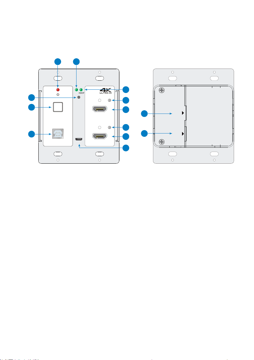
3. Panel Description ............................................................................................. 6
3.1 HDMI 4K HDBaseT Wallplate Transmitter............................................ 6
3.2 HDMI 4K HDBaseT Wallplate Receiver ................................................. 7
3.3 HDMI 4K HDBaseT Wallplate Control Panel ........................................ 9
4. System Connection ........................................................................................ 11
4.1 Usage Precaution .................................................................................. 11
4.2 System Diagram .................................................................................... 11
4.3 Speaker Wiring Configurations............................................................ 12
4.4 PoC Connection ..................................................................................... 13
4.5 USB Connection..................................................................................... 13
4.6 IR Connection......................................................................................... 14
4.7 RS232 Connection ................................................................................. 15
5. System Operation........................................................................................... 16
5.1 IR Learning ............................................................................................. 16
5.2 Button Control ....................................................................................... 17
5.3 GUI Control............................................................................................. 18
5.3.1 Device Control Tab ...................................................................... 19
5.3.2 Setting Tab.................................................................................... 20
5.3.3 Command Tab (RS232 Display Control).................................... 21
5.3.4 Network Tab ................................................................................. 23
5.3.5 GUI Update................................................................................... 24
5.4 Copy and Load Control Settings .......................................................... 25
6. Panel Drawing................................................................................................. 26
7. Troubleshooting & Maintenance.................................................................. 28
8. After-sales Service.......................................................................................... 30

HDMI 4K HDBaseT Wallplate Kit
1
1. Product Introduction
The HDMI 4K HDBaseT Wallplate Kit is a multi-function AV distribution system
designed to provide HDMI video switching, system control, video extension and
analog audio amplification in a convenient kit. The system consists of HDMI-4K
HDBaseT Transmitter, HDMI-4K HDBaseT Receiver and HDMI-4K Control Panel.
Utilizing the Valens Colligo series chips, power, control, video up to 4K, and audio
are transported over a single 40m (131ft)/70m (230ft) solid core Category cable
between the wall plate transmitter and the receiver. The wall plate control panel
connects to the wall plate transmitter with a second solid core Category cable. All
the power needed for the system is provided by the receiver. Additionally, the
receiver features a built-in web GUI for control and analog audio de-embedding to
a built-in 2x20 watt stereo amplifier.
1.1 Features
Two HDMI inputs can be switched freely.
HDMI video resolution is up to 4Kx2K@60Hz 4:2:0.
Extends 4K@60Hz 4:2:0 signal up to 40m (131ft) and 1080p@60Hz signal up to
70m (230ft) via a single CATx cable.
USB for smart board connection.
Supports HDCP 1.4.
Supports MIC input.
2x20Watt@4Ohm amplifier output.
Customizable control panel, support IR learning.
Copy and load IR and RS232 control settings.
Supports GUI control.
Supports UPNP.
Micro USB for firmware upgrade.

HDMI 4K HDBaseT Wallplate Kit
2
1.2 Package List
Transmitter
1x HDMI 4K HDBaseT Wallplate Transmitter
Receiver
1x HDMI 4K HDBaseT Wallplate Receiver
2x Mounting Ears with 4 Screws
4x Plastic Cushions
1x 4-pin Terminal Block
3x 3-pin Terminal Blocks
1x 2-pin Terminal Block
1x IR Emitter
1x USB-A to USB-B Cable
1x Power Adapter (DC 24V 2.71A)
Control Panel
1x HDMI 4K HDBaseT Wallplate Control Panel
1x White Faceplate
1 x User Manual
Note:Please contact your distributor immediately if any damage or defect in the
components is found.

HDMI 4K HDBaseT Wallplate Kit
3
2. Specification
2.1 HDMI 4K HDBaseT Wallplate Transmitter
Video
Video Input (1) HDMI IN 1, (1) HDMI IN 2
Video Input Connector (2) 19-pin type-A female HDMI
Video Output (1) PoC IN/HDBT OUT, (1) POWER/RS232
Video Output Connector (2) RJ45
Control
Control Port (1) TO PC, (1) FIRMWARE
Control Connector (1) Type-B USB, (1) Micro USB
General
Video Resolution Up to 4Kx2K@60Hz 4:2:0
Transmission Mode HDBaseT
Transmission Distance
CAT5e/6:
4K@60Hz 4:2:0 ≤ 35 meters (115 feet),
1080p@60Hz ≤ 60 meters (197 feet)
CAT6a/7:
4K@60Hz 4:2:0 ≤ 40 meters (131 feet),
1080p@60Hz ≤ 70 meters (230 feet)
Bandwidth 10.2Gbps
HDMI Version 1.4
HDCP Version 1.4
Operation Temperature -5~ +55℃
Storage Temperature -25 ~ +70℃
Relative Humidity 10%-90%
Dimension (W*H*D) 105mm x 89mm x 44mm
Net Weight 242g

HDMI 4K HDBaseT Wallplate Kit
4
2.2 HDMI 4K HDBaseT Wallplate Receiver
Video
Video Input (1) HDBT IN/PoC
Video Input Connector (1) RJ45
Video Output (1) TO DISPLAY
Video Output Connector (1) 19-pin type-A female HDMI
Audio
Audio Input (1) MIC
Audio Input Connector (1) 3-pin terminal block
Audio Output (1) 2x20Watt@4Ω, (1) LINE OUT
Audio Output Connector (1) 4-pin terminal block, (1) 3-pin terminal block
Audio Format
HDMI embedded audio: PCM/Dolby/DTS
MIC input audio: PCM
Analog output audio: PCM
Control
Control (1) TCP/IP, (1) FROM TOUCHSCREEN, (1) IR OUT, (1) RS232,
(1) REMOTE MUTE
Control Connector (1) RJ45, (1) Type-A USB, (1) 3.5mm mini jack, (1) 3-pin terminal
block, (1) 2-pin terminal block
General
Video Resolution Up to 4Kx2K@60Hz 4:2:0
Transmission Mode HDBaseT
Transmission Distance
CAT5e/6:
4K@60Hz 4:2:0 ≤ 35 meters (115 feet),
1080p@60Hz ≤ 60 meters (197 feet)
CAT6a/7:
4K@60Hz 4:2:0 ≤ 40 meters (131 feet),
1080p@60Hz ≤ 70 meters (230 feet)
Bandwidth 10.2Gbps
HDMI Version 1.4
HDCP Version 1.4
Power Supply Input:100V~240V AC; Output: 24V DC 2.71A
Power Consumption 55W (Max)
Operation Temperature -5~ +55℃
Storage Temperature -25 ~ +70℃

HDMI 4K HDBaseT Wallplate Kit
5
Relative Humidity 10%-90%
Dimension (W*H*D) 250mm x 31mm x 130mm
Net Weight 682g
2.3 HDMI 4K HDBaseT Wallplate Control Panel
Port
Control (1) CONFIG, (1) POWER/RS232
Control Connector (1) Type-A USB, (1) RJ45
Other (1) Volume Knob, (4) Buttons (ON, OFF, HDMI 1, HDMI 2),
(1) Built-in IR sensor
Operation Temperature -5~ +55℃
Storage Temperature -25 ~ +70℃
Relative Humidity 10%-90%
Dimension (W*H*D) 114mm x70mm x 34mm
Net Weight 140g

HDMI 4K HDBaseT Wallplate Kit
6
3. Panel Description
3.1 HDMI 4K HDBaseT Wallplate Transmitter
①POWER LED: The LED illuminates red when power is applied.
②LINK LED: The LED illuminates green when there is a valid HDBaseT
connection with the receiver. The LED is off when there is no valid link.
③HDCP LED: The LED illuminates green when there is HDMI video traffic with
HDCP. It will blink green when there is HDMI video traffic without HDCP and
will be off when there is no HDMI video traffic.
④RESET: Press this button to reboot the transmitter.
⑤SOURCE SELECT: Blue-backlit button for source selection.
⑥TO PC: Type-B USB to connect Host PC to receive USB control signal from
receiver.
⑦HDMI IN 1 LED: The LED illuminates yellow when the source device is
connected to the HDMI input 1 port. It will turn green when the HDMI input 1
source is selected as input.
⑧HDMI IN 1: Type-A female HDMI input port to connect an HDMI source device.
PoC IN
HDBT OUT
PO WER
RS232
PoC IN
HDBT OUT
PO WER
RS232
LINK
RESET
HDMI IN 1
FIRMWARE
HDMI IN 2TO PC
SOURCE SELECT
12
3
7
8
9
10
12
13
11
4
5
6

HDMI 4K HDBaseT Wallplate Kit
7
⑨HDMI IN 2 LED: The LED illuminates yellow when the source device is
connected to the HDMI input 2 port. It will turn green when the HDMI input 2
source is selected as input.
⑩HDMI IN 2: Type-A female HDMI input port to connect an HDMI source device.
⑪FIRMWARE: Micro-USB port for firmware upgrade.
⑫PoC IN/HDBT OUT: RJ45 port to connect the HDBT IN/PoC port of receiver by
CATx cable. The transmitter can be powered by this port once the receiver has
been powered up.
⑬POWER/RS232: RJ45 port to connect the POWER/RS232 port on the control
panel via CATx cable to receive RS232 control signal and power the control
panel.
3.2 HDMI 4K HDBaseT Wallplate Receiver
①FIRMWARE: Micro-USB port for firmware upgrade.
②LED indicators:
ON: The LED illuminates green when the system is in normal working
status.
LINK: The LED illuminates green when there is a valid HDBaseT connection
with the transmitter. The LED is off when there is no valid link.
HDBT IN/PoC TO DISPLAY
RL
LINE OUTIR OUT DC 24V
TCP/IP TOUCHSCREEN
FR OM
RS232
Tx Rx
OUTPUT CONTROL MIC
NETWORK INPUT
MIC
2x20Watt 4@
Ω
MICLINE
REMOTE
MUTE
AUDIO
ON LINK HDCP
FIRMWARE
1
10 11 12 13 14 15
456789
23

HDMI 4K HDBaseT Wallplate Kit
8
HDCP: The LED illuminates green when there is HDMI video traffic with
HDCP. It will blink green when there is HDMI video traffic without HDCP and
will be off when there is no HDMI video traffic.
③POWER LED: The LED illuminates red when power is applied.
④TCP/IP: RJ45 port to connect the control device (e.g. PC) to control the system
by GUI.
⑤HDBT IN/PoC: RJ45 port to connect the PoC IN/HDBT OUT port of transmitter
by CATx cable.
⑥TO DISPLAY: Type-A female HDMI output port to connect a display device (e.g.
Projector).
⑦FROM TOUHSCREEN: Type-A USB port to connect a touch screen device (e.g.
Smart Board) to transmit USB signal back to the Host PC. The port also can be
connected to an interactive projector to achieve on-line handwriting
annotation, but it can’t be synchronized to the Host PC.
⑧IR OUT: 3.5mm mini jack to connect IR emitter to control the display device.
⑨RS232: 3-pin terminal block to connect the display device (e.g. Projector) for
RS232 control.
⑩REMOTE MUTE: 3-pin terminal block to connect the fire alarm system. When
the fire alarm signal input, the audio output will be set to mute.
⑪LINE OUT: 3-pin terminal block to connect an audio broadcast device to output
HDMI embedded audio and MIC audio in mixed mode. In additional, the port
can be connected to a sound recorder for sound recording.
⑫LINE/MIC Level Selector Switch:
When the switch turns to “MIC”, the microphone input is connected to
dynamic microphone. There are two different connections:
1) Unbalanced connection:
“╧” connects to ground, and “-” connects to signal.
2) Balanced connection:
“+” connects to positive, “-” connects to negative and “╧” connects to
ground.

HDMI 4K HDBaseT Wallplate Kit
9
When the switch turns to “LINE”, the microphone input is connected to
normal or wireless microphone. There are two different connections:
1) Unbalanced connection:
“╧” connects to ground, and “-” connects to signal.
2) Balanced connection:
“+” connects to positive, “-” connects to negative and “╧” connects to
ground.
⑬MIC: 3-pin terminal block to connect wireless microphone and compatible with
MIC and LINE audio. When connect PC or other audio input device besides
microphone, only “-”and “ ” pins need to be used.
⑭2x20Watt@4Ω: 4-pin terminal block to connect speakers for audio mixing
output.
⑮DC 24V: Power port for power adapter connection.
3.3 HDMI 4K HDBaseT Wallplate Control Panel
①MIC LED: The LED illuminates blue when the MIC audio is selected to be
adjusted.
FIRMWARE
POWER
RS232
2
4
6
5
7
9
8
110 11
3

HDMI 4K HDBaseT Wallplate Kit
10
②SOURCE LED: The LED illuminates blue when the source audio is selected to be
adjusted.
③VOLUME: Press and hold this button for three seconds to select MIC or
SOURCE audio to be adjusted. Rotate the button to turn up or turn down the
selected audio. Press the button to mute or unmute the current audio source.
④ON: Blue-backlit button. It can be programed by IR learning to turn on the
display device.
⑤OFF: Blue-backlit button. It can be programed by IR learning to turn off the
display device.
⑥HDMI 1: Press this blue-backlit button to select the HDMI input 1.
⑦HDMI 2: Press this blue-backlit button to select the HDMI input 2.
⑧IR: Built-in IR senor to receive IR signal from IR remote.
⑨CONFIG: Type-A USB port to connect U-disk to copy or load control settings.
⑩POWER/RS232: RJ45 port to connect the POWER/RS232 port of the transmitter
via CATx cable to transmits RS232 control signal and power the control panel.
⑪FIRMWARE: Micro-USB port for firmware upgrade.

HDMI 4K HDBaseT Wallplate Kit
11
4. System Connection
4.1 Usage Precaution
Make sure all components and accessories are included before installation.
System should be installed in a clean environment with proper temperature
and humidity.
All of the power switches, plugs, sockets, and power cords should be insulated
and safe.
All devices should be connected before power on.
4.2 System Diagram
Note:
Connect HDBT ports via straight-thru CAT5e/6 cable with TIA/EIAT568B standard
terminations at both ends.
The distance is less than 40m at 4K or 70m at 1080p between transmitter and
receiver.
HDBT IN PoC
/
TO DISPLAY
RL
LINE OUT
IR OUT
DC 24V
TCP IP
/
TOUCHSCREEN
FROM
RS232
Tx Rx
OUTPUT CONTROL MICNETWORK INPUT
MIC
2x20Watt 4
@
MICLINE
REMOTE
MUTE
AUDIO
Fire Alarm
System
LINK
RESET
HDMI IN 1
FIRMWARE
HDMI IN 2
TO PC
SOURCE SELECT
PoC IN
HDBT O UT
POWE R
RS23 2
CAT5e 6A Cable
/
Smart Board
Projector
Laptop Laptop
Transmitter
Standby
Receiver
Wireless Mic
RS232
Control Panel

HDMI 4K HDBaseT Wallplate Kit
12
4.3 Speaker Wiring Configurations
4Ω Load with 4Ω speakers:
4Ω Load with 8Ω Speakers:

HDMI 4K HDBaseT Wallplate Kit
13
4.4 PoC Connection
The system supports PoC, which allows several terminals share the same power
supply and eliminates the need for extra power supply at the remote nodes.
Connect a 24V DC power adapter to the power port of receiver, the transmitter and
control panel can be energized synchronously with PoC solution, see the picture
below:
4.5 USB Connection
The receiver has a USB port (FROM TOUCH SCREEN) to connect smart board.
When user make notes on smart board, the receiver will receive the signal from
smart board and send it back to the Host PC. Please refer to the return path of USB
signal as shown as below.
Note: The special USB control cable is required if the connection distance is more than
4m/13ft between the receiver and the smart board.
H D B T IN /P o C TO DISPLAY
RL
LINE O UT
IR O U T DC 24V
T C P /IP TOUCHSCREEN
FRO M
RS 232
Tx Rx
OUTPUT CONTROL M ICNETW O RK IN P U T
M IC
2x20W att@ 4
Ω
M ICL IN E
REM O TE
M UTE
A U D IO
L IN K
RESET
HDMIIN 1
F IR M W A R E
HDMIIN 2TO PC
SOURC E SELECT
P o C IN
H D B T O U T
P O W ER
R S 2 3 2
C A T5e/6A C able
Transm itter
St
andby
R eceiver
R S 232
C ontrolP anel
P ow eradaptor
D C 24V 2.71A
USB Signal
HDBT IN/PoC TO D ISPL AY
RL
LINE O UTIR OUT DC 24V
TCP/IP TOUCHSCREEN
FROM
RS232
Tx Rx
OUTPUT CONTROL MICNETWORK INPUT
MIC
2x20Watt 4@
Ω
MICLINE
REMOTE
MUTE
AUDIO
L IN K
RESET
HDMIIN 1
FIRM W ARE
HDMIIN 2TO PC
SOURC E SELECT
P o C IN
H D B T O U T
P O W ER
R S 2 3 2
Transm itter
R eceiver
Laptop
P rojector
Smart Board
USB Signal
USB Signal

HDMI 4K HDBaseT Wallplate Kit
14
4.6 IR Connection
The control panel provides a built-in IR sensor and the receiver provides an IR OUT
port for IR pass-through control. Connect IR emitter to the IR OUT port of the
receiver, and then put the IR emitter close to the display device (e.g. Projector), and
put the IR remote of display device close to the built-in IR sensor, the display device
can be controlled by pressing IR remote.
IR Signal
IR Signal
HDBT IN/PoC TODISPLAY
RL
LINE O UTIR OU T DC 24 V
TCP/IP TOUCHSCREEN
FRO M
RS232
Tx Rx
OUTPUT CONTROL MICNETWORK INPUT
MIC
2x20Watt 4@
Ω
MICLINE
REMOTE
MUTE
AUDIO
LINK
RESET
HDMI IN 1
FIRMWARE
HDMI IN 2TO PC
SOURCE SELECT
P o C IN
H D B T O U T
P O W E R
R S 2 3 2
P rojector
Transmitter
St
andby
Receiver
Control Panel

HDMI 4K HDBaseT Wallplate Kit
15
4.7 RS232 Connection
The receiver provides an additional RS232 interface to connect the display device,
and then the display device can be controlled by sending RS232 commands via
GUI. Please refer to 5.3.3 Command Tab.
HDBT IN PoC
/
TO DISPLAY
RL
LINE OUT
IR OUT
DC 24V
TCP IP
/
TOUCHSCREEN
FROM
RS232
Tx Rx
OUTPUT CONTROL MICNETWORK INPUT
MIC
2x20Watt 4
@ Ω
MICLINE
REMOTE
MUTE
AUDIO
LINK
RESET
HDMI IN 1
FIRMWARE
HDMI IN 2
TO PC
SOURCE SELECT
PoC IN
HDBT O UT
POWE R
RS23 2
CAT5e 6A Cable
/
Projector
Laptop
Transmitter
Receiver
RS232 Signal
RS232 Signal

HDMI 4K HDBaseT Wallplate Kit
16
5. System Operation
5.1 IR Learning
The IR learning function allows user to use the buttons of control panel to displace
some keys of IR remote which can control display device or other devices. The
control panel has four buttons: ON, OFF, HDMI 1 and HDMI 2, but HDMI 1 and
HDMI 2 buttons do not support IR learning function, because they are designed for
source selection.
Operation Procedure:
1) Press and hold HDMI 1 until the ON and OFF light up, and then release
HDMI 1, the HDMI 1 will go dark to enter IR learning mode.
2) Press ON to enter IR learning status, and it will keep blinking blue.
3) Press the corresponding key (such as power on key) on IR remote,
meanwhile, put IR remote close to the IR sensor of control panel.
4) Once set up successfully, the button ON will stop blinking.
5) Next, repeat the above steps to set another button OFF.
6) Finally, Press and hold HDMI 2 to exit IR learning mode.
Apply IR Learning Function:
1) Press ON to turn on the display device.
2) Press OFF to turn off the display device.
Note:
When the control panel is in the IR learning mode, press and hold HDMI 2for five
seconds can exit.
If there is no operation for sixty seconds, the control panel will automatically exit the
IR learning mode.
All buttons will go dark while the control panel exits IR learning mode successfully.
Table of contents
Other AvLab Extender manuals