Avidyne Entegra Manual


Page Chg
Cover…...0
Page #.....1
TOC-1.....1
TOC-2….1
1-1………0
1-2……...0
1-3……...0
1-4……...0
1-5……...0
1-6………0
1-7………0
1-8………0
1-9………0
1-10….....0
1-11……..1
1-12……..1
1-13……..1
1-14……..1
2-1……….0
2-2……….0
2-3……….0
2-4……….0
3-1……….0
3-2……….0
3-3……….0
3-4……….0
3-5……….0
3-6……….0
3-7……….0
3-8……….0
3-9……….0
Page Chg
3-10……..0
3-11……..0
3-12……..0
3-13……..0
3-14……..0
4-1……….1
4-2……….0
4-3……….0
4-4……….0
4-5……….1
4-6……….1
4-7……….1
5-1……….0
5-2……….0
5-3……….0
5-4……….0
5-5……….0
5-6……….0
5-7……….0
5-8……….0
5-9……….0
5-10……..0
5-11……..0
5-12……..0
5-13……..0
5-14……..0
5-15……..0
5-16……..0
5-17……..0
5-18……..0
5-19……..0
Page Chg
5-20……..0
5-21……..0
5-22……..0
5-23……..0
5-24……..0
6-1………0
6-2…….…1
6-3……….1
6-4……….1
6-5……….0
6-6……….1
6-7……….0
6-8……….0
6-9……….0
6-10……..0
6-11……..1
6-12……..0
6-13……..0
6-14……..0
7-1……….0
7-2……….0
8-1……….0
8-2……….0
8-3……….0
8-4……….0
9-1……….1
9-2……….0
9-3………0
9-4……….0
9-5……….1
9-6……….1
Page Chg
9-7……….1
9-8……….1
10-1……..1
10-2…….0
10-3……..0
10-4……..0
10-5……..0
10-6……..1
10-7……..1
10-8……..1
10-9……..1
10-10……1
11-1……..1
11-2……..0
11-3……..1
11-4……..1
11-5……..1
11-6……..1
12-1……..0
12-2……..0
12-3……..0
12-4……..0
12-5……..0
12-6……..0
13-1……..0
13-2……..0
13-3……..0
13-4……..0
13-5……..0
13-6……..0
13-7……..0
Page Chg
13-8……..0
A-1………0
A-2………0
A-3………0
A-4………0
A-5………0
A-6………0
A-7………0
A-8………0
A-9………0
A-10.…….0
A-11……..0
A-12……..0
A-13……..1
A-14……..1
B-1………0
B-2………0
B-3………0
B-4………0
B-5………0
B-6………0
B-7………0
B-8………0
B-9………0
B-10……..0
B-11……..0
B-12……..0
C-1………0
C-2………0
C-3………0
C-4……..0
Page Chg
C-5……..0
C-6……..0
D-1……..1
D-2……..0
D-3……..0
D-4……..0
D-5……..0
D-6……..0
D-7……..0
D-8……..0
D-9……..0
D-10……0
D-11……0
D-12……0
D-13……0
D-14……0
E-1……..0
E-2……..0
E-3……..0
E-4……..0
E-5……..0
E-6……..0
Indx-1….1
Indx-2….1
IBC…….0
OBC……1
Change 1


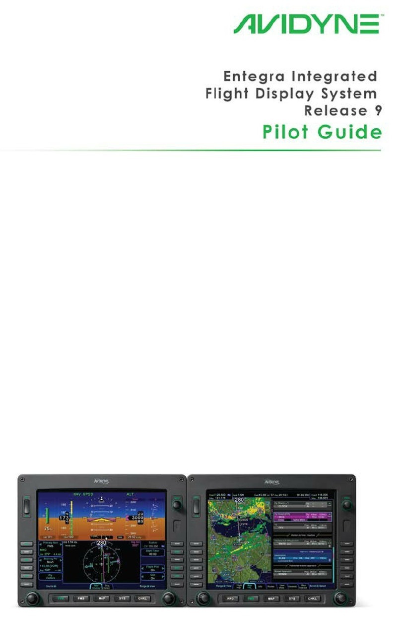
Entegra Flight Display System | Release 9 PILOT GUIDE
TABLE OF CONTENTS
1System Overview ............................................................. 1-2
FUNCTIONAL OVERVIEW ..........................................................1-2
BASIC CONCEPTS......................................................................1-3
REDUNDANCY ............................................................................1-9
MODULAR DESIGN...................................................................1-10
DATABUS...................................................................................1-10
HARDWARE MODULARITY ......................................................1-10
SOFTWARE MODULARITY.......................................................1-11
DISPLAY ENHANCEMENTS .....................................................1-12
AIRCRAFT CONFIGURATION MODULE ..................................1-12
HOW TO USE THE REST OF THIS MANUAL...........................1-13
2Normal Startup Sequence............................................... 2-2
SYSTEM POWER ........................................................................2-2
BRIGHTNESS CONTROLS .........................................................2-2
STARTUP INDICATIONS.............................................................2-2
3Ground Operations.......................................................... 3-2
ELECTRONIC CHECKLIST .........................................................3-2
ENTERING A FLIGHT PLAN........................................................3-3
USE OF THE ENGINE TAB .........................................................3-8
SETTING UP THE RADIOS AND TRANSPONDER ....................3-9
SETTING UP THE AUTOPILOT.................................................3-11
TAXI CHARTS............................................................................3-13
ALTIMETER SETTING...............................................................3-13
4Departure.......................................................................... 4-2
DEPARTURE PROCEDURES .....................................................4-2
VSPEEDS ON ASI........................................................................4-5
ENGINE INDICATION ON ADI.....................................................4-6
5Cruise / Enroute ............................................................... 5-2
NAVIGATIONAL SITUATIONAL AWARENESS...........................5-2
PRECISION FLYING....................................................................5-3
ENGINE LEANING.......................................................................5-5
USE OF THE MAP .......................................................................5-6
FMS OPERATIONS......................................................................5-9
USE OF NEAREST FUNCTION.................................................5-18
DATALINK OPERATIONS..........................................................5-18
AUTOPILOT OPERATIONS.......................................................5-24
6Arrivals/Approaches/Landing......................................... 6-2
ENROUTE DESCENTS................................................................6-2
ENTERING AN ARRIVAL AND APPROACH...............................6-3
USE OF THE SPLIT PAGES........................................................6-6
FLYING AN AUTOPILOT COUPLED APPROACH......................6-8
USE OF THE TIMER..................................................................6-13
CHANGE 1

TAXI CHARTS............................................................................6-14
7Diverts/Missed Approaches............................................ 7-2
MISSED APPROACH...................................................................7-2
RETRY APPROACH ....................................................................7-2
8Night Operations.............................................................. 8-2
IFD DISPLAY BRIGHTNESS .......................................................8-2
IFD BEZEL BRIGHTNESS...........................................................8-2
KEYBOARD DISPLAY BRIGHTNESS .........................................8-2
KEYBOARD BEZEL BRIGHTNESS.............................................8-2
CHARTS LIGHTING SCHEME.....................................................8-2
DISPLAY OF TERRAIN ON MAP.................................................8-3
9System Alerts................................................................... 8-1
CAS SYSTEM ..............................................................................9-2
MISCOMPARES...........................................................................9-5
10 System Failures ............................................................. 10-2
POWER DISTRIBUTION............................................................10-2
LOSS OF IFD .............................................................................10-2
LOSS OF DISPLAY....................................................................10-3
LOSS OF KEYBOARD...............................................................10-4
LOSS OF AHRS, AIR DATA OR ADAHRS ................................10-6
WARMSTART ............................................................................10-6
FAST ERECT .............................................................................10-8
LOSS OF ENGINE DATA...........................................................10-9
KEYBOARD CONTRAST ADJUST............................................10-9
11 System Setup / User Preferences ................................ 11-2
MAIN ........................................................................................11-2
DISPLAY ....................................................................................11-3
FMS ........................................................................................11-4
MAP ........................................................................................11-5
DATABLOCKS ...........................................................................11-5
AUTOPILOT ...............................................................................11-6
12 System Updates............................................................. 12-2
DATA UPDATES........................................................................12-2
DATALOGS DOWNLOAD..........................................................12-4
SOFTWARE UPDATES .............................................................12-6
13 Release 7/8 to Release 9 Differences........................... 13-2
Appendix A – PFD ..................................................................A-1
Appendix B – FMS Pages......................................................B-1
Appendix C – Map Pages.......................................................C-1
Appendix D – System Pages.................................................D-1
Appendix E – Checklist Pages..............................................E-1
Index............................................................................................1
Change 1
System Overview 1-1
1System Overview ............................................................. 1-2
FUNCTIONAL OVERVIEW ..........................................................1-2
BASIC CONCEPTS......................................................................1-3
Page Function Keys................................................................................1-3
Line Select Keys .....................................................................................1-4
Display Formats......................................................................................1-5
ADI Upper Half........................................................................................1-6
Primary Navigation Source .....................................................................1-6
Full Alpha-numeric keyboard with display...............................................1-6
Live Edits.................................................................................................1-7
Overlays..................................................................................................1-8
Panning...................................................................................................1-8
Integration with other systems ................................................................1-8
Caution-Warning System........................................................................1-9
Datablocks ..............................................................................................1-9
REDUNDANCY ............................................................................1-9
MODULAR DESIGN...................................................................1-10
DATABUS...................................................................................1-10
HARDWARE MODULARITY ......................................................1-10
SOFTWARE MODULARITY.......................................................1-11
DISPLAY ENHANCEMENTS .....................................................1-12
Cleaning the Display.............................................................................1-12
AIRCRAFT CONFIGURATION MODULE ..................................1-12
HOW TO USE THE REST OF THIS MANUAL...........................1-13

1-2 System Overview
1 System Overview
FUNCTIONAL OVERVIEW
The Avidyne Entegra Release 9 flight display system supports the
following functions:
•Primary Flight Display
•Flight Management System
•WAAS GPS Navigation
•VHF Radio Nav/Com
•Attitude and Air Data Sensors
•Moving Map
•Weather Datalink
•Traffic
•Lightning
•Electronic Approach Plates
•Engine Display
•Electronic Checklist
•Data Logging
•Caution-Warning System

System Overview 1-3
The system has been designed for single-pilot IFR operation and
features a Page and Tab user interface.
Functions revolve around the five Page Function Keys that
appear across the bottom edge of the bezel. Each of the five
functional pages has associated tabs, which contain related data,
often in different views. These functions and tabs are covered in
detail throughout this reference manual. The primary method for
accomplishing a task will be outlined, and if applicable, alternative
methods will be explained in the appendices. One consistent
message that will be emphasized is the method and position of
displaying data does not change between these different views
and tabs. Avidyne strongly believes in the concept “Fly like you
train and train like you fly”. In other words, the same views used
on a daily basis are identical to what is available during
emergency and reversionary conditions.
The reversionary capability is inherent to the redundancy of the
Integrated Flight Displays (IFD) and the dual-databus
architecture. The system architecture allows selection of five
separate display functions on any display. This eliminates the
need for special reversionary display modes with reduced
functionality, and reduces complexity and training requirements
for the pilots.
BASIC CONCEPTS
PAGE FUNCTION KEYS
The 5 buttons along the bottom of the IFD bezel are called Page
Function Keys. Each key is labeled by function:
•PFD (Primary Flight Display)
•FMS (Flight Management System)
•Map (Moving Map)
•SYS (System Pages)
•CHKL (Electronic Checklist)
Each page has a number of associated tabs. Each Page
Function key has a left and right rocker nature to it. Select the
page of interest by pressing the middle of the Page Function Key
and navigate through the available tabs by pressing the left or

1-4 System Overview
right side of the Page Function Key. Continue pressing one side
of the function key to automatically step through the tabs.
Page Function Keys and Tabs
LINE SELECT KEYS
Line Select Keys, typically abbreviated to LSK in this manual,
are the buttons found along the left and right sides of the bezel. A
label, just inside the bezel – adjacent to the physical LSK,
indicates the function of the LSK. Each LSK is capable of being
individually backlit to help the pilot identify the correct LSK.
Pressing the LSK either performs the labeled action or changes
the state, which is indicated by the left and right arrows. These
LSKs function by rocking left or right on the key. For the cases
where there is a list of selectable options, browse the list in either
direction by pressing the left or right side of the LSK. This
becomes a time saving technique when trying to rapidly navigate
a large list and minimizes time recovering from list overshoots by
providing the ability to back up one selection.
LSK Types
•State LSKs – Right and left arrows indicate a list of
choices. Traverse the list by rocking left or right on the
line select key.
•Action LSKs – Pressing the LSK enables the action
indicated on the label.

System Overview 1-5
COOL FEATURE
Addressable Line Select Keys On any given page
only LSKs that can perform the labeled function are
backlit. Keys that are non-functional are intentionally
unlit. This is to visually “quiet” the display, reduce
time searching for a desired button and also
minimize extra pilot actions caused by inadvertently
pressing the wrong button. This feature is especially
useful at night in a darkened cockpit.
DISPLAY FORMATS
•Half format – The PFD attitude indicator, airspeed,
altimeter and vertical speed indicators are always on the
top half of the page. The bottom half of the page is
dependent on which Page Function Key and tab are
selected. Whenever the bottom half of the page is not a
traditional HSI, the lower edge of the ADI has a
perspective compass and Horizontal Deviation Indicator
(HDI).
•Full format – The function selected (e.g. Map or Chart)
takes up the entire screen. Associated line select keys
can be pilot-selected to time out in preset durations or
never.
•Datablock format – The left and right sides of the IFD
are populated with various pilot-selectable datablocks.
•Split format – The IFD is split vertically, down the center,
allowing two distinct functions to be displayed at the
same time. Examples include Map-Chart and Map-FLP.
The ND box concept refers to the rectangular section on the
lower half of the PFD pages. It is most noticeable on the PFD
where the upper half is always a PFD view. The ND box is filled
based on which Page Function Key is pressed along the bottom
edge of the IFD bezel,
All pages are available at all times with only one key press.

1-6 System Overview
ADI UPPER HALF
The system has been configured to recognize in which position
each display is located in the cockpit. This means that the PFD
will always display an ADI on the upper half of the display,
regardless of which page function keys are pressed along the
bottom of the bezel.
PRIMARY NAVIGATION SOURCE
The means of selecting which nav source is driving the deviation
indicators on the PFD and HSI as well as the source driving the
autopilot when the autopilot is in NAV mode comes from the
Primary Nav LSK on the PFD. Choices are FMS, Nav1, Nav2.
The FMS will automate the Primary Nav LSK mode change from
FMS to Nav 1-2 and automatically toggle the autopilot from GPSS
to NAV on intercepting a localizer and conversely, toggle the
autopilot from NAV to GPSS and change the Primary Nav LSK
when going missed after an approach.
FULL ALPHA-NUMERIC KEYBOARD WITH DISPLAY
The system comes equipped with an alpha-numeric keyboard to
assist control of navigation and communication. It has two rows of
dedicated function keys along to the top edge that are grouped
together in logical functions to include:
•Com Radio Selection
•Nav Radio Selection
•Auxillary Radio Functions
•Transponder Mode Selection
•FMS Shortcuts (Direct-To, Nearest, Procedures, Vectors)
•Map panning and control
The keyboard is the primary location to conduct all Com Tuning. It
is also the primary location for autopilot target setting using the
dedicated knob controls along the bottom edge. Nav tuning is
automatic in this system in that the FMS automatically tunes all
navaids that are part of the active flight plan. As a means of
backup, manual nav tuning can be conducted from the keyboard.

System Overview 1-7
The keypad is a QWERTY layout with a few special function
buttons along the outer edges and a row of number keys along
the top of the keypad.
Just above the keypad is a display that is split into two distinct
areas: a semi-permanent display of the com and nav frequencies
on the left half of the display and a set of user-configurable
datablocks in the right half. This datablock area is temporarily
replaced by a display that is relevant to the operation being
performed on the keyboard (e.g. com tuning, transponder code
input, autopilot target setting, FMS data entry, etc).
Keyboard
LIVE EDITS
All edits are “live edits” in that they are immediately applied.
Examples include:
•Course Entry on PFD
•Com tuning on keyboard (new frequency becomes the
active radio standby freq)
•Nav tuning on keyboard (new frequency becomes the
active radio standby freq)
•Waypoint name entries in flight plans
•Autopilot targets (Altitude, Heading, Vertical Speed)
•Waypoint deletions in flight plans

1-8 System Overview
OVERLAYS
The system supports overlays of data are controlled via the LSKs.
Examples on the Map pages include being able to turn on or off:
•Datalink NOWrad weather displays
•Datalink Icing displays
•AIRMETS/SIGMETS
•METAR flags
•Flight Plan (on PFD HSI)
•CDI (on PFD HSI)
PANNING
The map pages support a panning capability. Using a joystick on
the keyboard, any map page on the MFD provides the ability to
pan anywhere on the map, zoom in or out as desired, hover over
hotspots and see information boxes pop-up.
INTEGRATION WITH OTHER SYSTEMS
Integration is provided with other systems such as traffic
awareness system (TAS), transponder, audio select panels and
autopilot.
Traffic sensor data is permanently displayed on all map pages,
the ND box and in a dedicated traffic thumbnail display. Traffic
sensor modes and display ranges can be controlled through
various LSK options.
The level of transponder integration depends on which
transponder the airplane is equipped. If equipped with a remote-
mounted Mode C or Mode S transponder, all transponder mode
and code changes are commanded through the keyboard and
this data is displayed prominently on the displays. If equipped
with a panel mount transponder, most of the transponder mode
and code control, as well as display, remain on the panel mount
transponder.
The level of audio select panel integration depends on which
audio panel the airplane is equipped. If equipped with an
Avidyne-compatible PS Engineering PMA8000B Audio Select

System Overview 1-9
Panel, the PFD displays the frequency and station identifier of the
active com frequency just below the VSI in the primary field of
view.
There are additional capabilities controlling the S-TEC 55X over
previous Avidyne flight displays. In this system, the FMS will
issue autopilot mode commands to/from NAV and GPSS as it
follows along the active flight plan. This eliminates the need for
manually pressing the autopilot control head buttons and reduces
pilot workload in many flight scenarios.
CAUTION-WARNING SYSTEM
A caution warning system is provided in this system, comprising
of a set of Master Caution “Warning” and “Caution” lamps in the
primary field of view of the PFD; a system of Warning (red),
Caution (amber), and Advisory (cyan) alert messages that are
displayed to the pilot, and a dedicated page for display of all
active alerts.
DATABLOCKS
As noted earlier in this section, many pages are presented in a
datablock format on the MFD and keyboard. Data such as
waypoint and nav data, com/nav frequencies, transponder codes,
UTC or Local time, and engine parameters are all selectable for
display in these datablock fields. The keyboard display is also
configured to allow display of pilot-selectable datablock fields.
REDUNDANCY
Since both IFDs are identical pieces of hardware, running
identical software, they are 100% interchangeable. These IFDs
and keyboards are all interconnected via a dual, digital Databus.
This means all sensor data is available to all IFDs, all the time.
External sensors (e.g. traffic, lightning, datalink, etc.) are
connected to the basic system via one or both of the I/O “blades”
and all IFDs have access to that information. The more sensors
that talk directly on the digital Databus, the less the wiring
required to support it, which translates directly to less weight and
less complexity.

1-10 System Overview
MODULAR DESIGN
This system was designed to be modular; modular in the overall
architecture, hardware, software and from a packaging
perspective. This approach produces future extensibility and
provides Avidyne with flexibility in adapting the system to meet
future needs.
DATABUS
One of the key modularity components employed in this system is
the databus. This dual, digital databus is peer-to-peer, meaning it
is not reliant on a single designated bus controller passing data
serially to every component on board. Instead, every component
individually passes data to the bus during a given time slot and
selects the data it is only interested in seeing from other
components.
For additional information on databuses and how they are
relevant to the behind-the-scenes operation of the system, see
this article “What’s Next in Avionics” accessible via this hyperlink:
http://www.avidyne.com/news/coverage.asp
A true dual-redundant peer to peer databus improves critical
sensor and computation modules are not “daisy-chained”
together in a manner that can create cascading failures. With a
true dual redundant databus, single-point failures remain just that,
single point failures. They do not adversely affect other vital,
otherwise operational functionality.
A true dual redundant databus design means true reliability and
redundancy. Unlike other systems that require complex, limited,
and unfamiliar reversionary modes this offers double critical
function redundancy via the dual redundant databus architecture.
HARDWARE MODULARITY
There is one spare modular avionics slot available for future
functions. When new requirements emerge or hardware
technology advances, a new module can be added or an existing
module may be replaced with an updated one. This enables an
easy upgrade path for existing aircraft in the field. The hardware
modules have considerable unused processing, memory and
communication bandwidth allowing for maximum functional

System Overview 1-11
expansion without changing the existing hardware. In many
cases, software upgrades may be accomplished without
removing units from the aircraft.
The image below shows the back of an IFD and a close up view
of the LRU blades that slide in.
The basic system consists of a FMS900w control panel, or
“keyboard” (not shown), and two 10.4” IFD5000i Integrated Flight
Displays (“IFDs”) that are self-contained units with an internal
card cage for LRUs; that means they are built with a number of
slots designed to fit individual component LRUs. These LRUs can
slide in and out of the IFD and include the ADAHRS, the WAAS
GPS, the digital VHF radios, and the I/O interface.
LRU modules as part of an integral chassis
Other variations of the system include single ADAHRS LRUs (vs.
dual ADAHRS) and FMS400 instead of FMS900w.
In the single ADAHRS configuration, the ADAHRS is physically
housed in the left IFD and the right IFD has an empty slot for the
missing LRU. The attitude and air data from the single ADAHRS
is still capable of being displayed on all IFDs.
Change 1
1-12 System Overview
The FMS400 is still a full-featured FMS but does not support
precision WAAS approaches (LPV), airways nor drop down
options for arrivals and departures. There is no capability to have
a combination of FMS900w and FMS400 systems in the same
airplane.
SOFTWARE MODULARITY
The software architecture is specifically designed to be
partitioned and promote the advantages of higher levels of
integration without compromising safety by generating the
unwanted side effects of failure propagation.
DISPLAY ENHANCEMENTS
These new displays are a second-generation display system with
enhanced characteristics over first generation displays systems
and include:
•768 x 1024 display resolution
•LED backlight technology
•1000 nit brightness
CLEANING THE DISPLAY
If the IFD screen should become dirty due to fingerprints or dust,
clean the screen using the following materials and methods:
•A clean, soft lint-free cloth such as 3M Ultra-Brite Cloth
#2011 or similar
•A cleaning solution composed of de-ionized water or
isopropyl alcohol (IPA). Use caution, as it is flammable.
Always apply the cleaning solution directly on the cloth.
Never spray cleaner directly on the screen.
The use of any 3rd party screen protector, especially those that
adhere directly to the IFD display glass, is not endorsed by
Avidyne and may void the warranty for any display related issue.
Change 1
System Overview 1-13
AIRCRAFT CONFIGURATION MODULE
An Aircraft Configuration Module (ACM) stores all aircraft-specific
avionics configuration information.
The ACM plugs directly into the back of an Integrated Flight
Display and remains with the aircraft harness. This means if an
entire IFD needs to be removed for service, or a replacement is
re-installed, calibrations, aircraft configuration, and pilot
preferences are automatically loaded into the replaced unit. This
saves significant maintenance time and reduces the likelihood of
data loss.
HOW TO USE THE REST OF THIS MANUAL
2 IFD configuration reference
When describing a function or behavior for a specific IFD, the
term PFD and MFD will frequently be used. In this context, the
left-most IFD will be referred to as the “PFD” and the right-hand
IFD will be referred to as the “MFD”.
Starting with Section 2, the manual is organized in a phase-of-
flight order. Alerts, Failures and Setup chapters follow, ultimately
ending with a number of appendices, which are organized by
Page Function Keys.
When viewing the electronic version of this reference manual,
there are several hyperlinks embedded in the text that provide
easy links to more detailed material. Double clicking the hyperlink
(indicated by underlined text) will automatically launch your
computer browser to the appropriate location.
Similarly, there are several short videos embedded in the
electronic version that add visual descriptions to the task or
Change 1
1-14 System Overview
feature being discussed. These are indicated by the movie
camera symbol in the proximity of the task or feature.
The electronic version of this guide contains a video clip.
Change 1
Other manuals for Entegra
1
Table of contents
Other Avidyne Avionic Display manuals

Avidyne
Avidyne IFD550 Manual

Avidyne
Avidyne IFD550 User manual

Avidyne
Avidyne Envision EXP5000 Manual

Avidyne
Avidyne Entegra EX5000 User manual

Avidyne
Avidyne IFD440 User manual

Avidyne
Avidyne 700-00182 Series Service manual

Avidyne
Avidyne Entegra EXP5000 Manual

Avidyne
Avidyne Envision EX5000 Manual

Avidyne
Avidyne IFD5 Series User manual

Avidyne
Avidyne IFD4 Series User manual