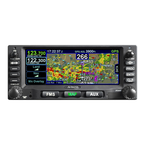
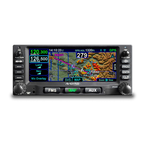
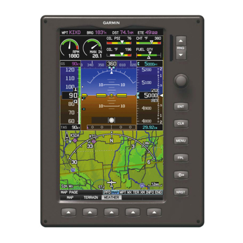
Avidyne 700-00182 Series Service manual

As installed in
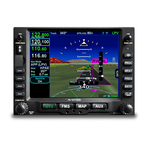
____________________________________
(Make and Model Airplane)
Reg. No. ____________ S/N______________
Confidential property of Avidyne Corporation
Not to be disclosed without permission
AVIDYNE
CORPORATION
Avidyne Corporation
4 Middlesex Green, Suite 221
561 Virginia Road
Concord MA 01742
Avidyne 700-00182-XXX and 700-00179-XXX
Integrated Flight Display
Instructions for Continued Airworthiness
Important Notice
With respect to the AML STC, the physical mounting of
antennas are specifically excluded from the approval in
the case of installations on the pressure vessel of
pressurized aircraft or composite aircraft unless
approved data is listed in the Master Document List of
the STC.

Avidyne 700-00182-XXX and 700-00179-XXX Instructions for Continued Airworthiness
Confidential property of Avidyne Corporation AVIFD-315
Not to be disclosed without permission Revision: 08, Date: 01/18/17
Page 2 of 2
Document Revision History
Document Number AVIFD-315 Control Category
Revision Description ECO Date
00 Initial Release ECO-13-199 08/30/13
01 AEG Comments ECO-13-350 09/27/13
02 Update Part Numbers ECO-13-405 01/20/14
03 Removing ADS-B ECO-14-059 03/03/14
04 Added 700-00179-XXX ECO-15-129 03/20/15
05 AEG Comments ECO-15-169 04/22/15
06 FAA Comments ECO-15-193 05/05/15
07
Update f or Release 10.2. Added
IFD410, IFD510, IFD545, IFD550, ARS
troubleshooting instructions and IFD550
figure
ECO-16-326 12/21/16
08 Address AEG comments sections 2, 6, 7 ECO-17-013 01/18/17

Avidyne 700-00182-XXX and 700-00179-XXX Instructions for Continued Airworthiness
Confidential property of Avidyne Corporation AVIFD-315
Not to be disclosed without permission Revision: 08, Date: 01/18/17
Page 3 of 3
Table of Contents
1. Introduction .......................................................................... 5
1.1 Applicability.................................................................................................................. 5
1.2 Definitions and Abbreviations...................................................................................... 6
1.3 Precautions.................................................................................................................. 6
1.4 Units of Measure.......................................................................................................... 7
1.5 Referenced Publications.............................................................................................. 7
1.6Distribution................................................................................................................... 7
2. Description ........................................................................... 8
2.1 Equipment Locations................................................................................................... 9
3. Control and Operation Information................................... 11
3.1 Page Function Keys................................................................................................... 12
3.2 Line Select Keys........................................................................................................ 12
4. Servicing Information......................................................... 12
5. Maintenance Instructions .................................................. 13
5.1 Scheduled Maintenance............................................................................................ 13
5.2 Recommended periodic scheduled servicing tasks .................................................. 13
5.3 Software Upgrade...................................................................................................... 14
6. Troubleshooting Information............................................. 15
7. Removal and Replacement Information ........................... 17
7.1 IFD5XX/IFD4XX Removal ......................................................................................... 17
7.2 IFD5XX/IFD4XX Installation ...................................................................................... 17
7.3 GPS Antenna Removal.............................................................................................. 17
7.4 GPS Antenna Installation........................................................................................... 17
7.5 Tray Removal ............................................................................................................ 18
7.6 Tray Installation ......................................................................................................... 18
7.7 System Setup and Checkout..................................................................................... 18
8. Application of Protective Treatments ............................... 19
9. Data ..................................................................................... 19
10. List of Special Tools........................................................ 19
Avidyne 700-00182-XXX and 700-00179-XXX Instructions for Continued Airworthiness
Confidential property of Avidyne Corporation AVIFD-315
Not to be disclosed without permission Revision: 08, Date: 01/18/17
Page 4 of 4
11. For Commuter Category Aircraft.................................... 19
12. Recommended Overhaul Periods .................................. 19
13. Airworthiness Limitations Section................................. 19
14. Revision........................................................................... 20
15. Assistance ....................................................................... 20
16. Implementation and Record Keeping ............................ 20
List of Figures
Figure 1: IFD5XX/IFD4XX Location - Single Engine.............................................................................. 9
Figure 2: IFD5XX/IFD4XX Location – Multi Engine .............................................................................10
Figure 3: IFD540/510 Unit.........................................................................................................................11
Figure 4: IFD4XX Unit................................................................................................................................11
Figure 5: IFD545/550 Unit.........................................................................................................................11

Avidyne 700-00182-XXX and 700-00179-XXX Instructions for Continued Airworthiness
Confidential property of Avidyne Corporation AVIFD-315
Not to be disclosed without permission Revision: 08, Date: 01/18/17
Page 5 of 5
1. Introduction
This document identifies the Instructions for Continued Airworthiness
(ICA) for the modification of the aircraft listed in AVIFD-318 Integrated
Flight Display STC Approved Model List by installation of an Avidyne
700-00182-XXX (IFD5XX) and/or 700-00179-XXX (IFD4XX) Integrated
Flight Display.
This ICA satisfies the requirements of 14 CFR 23.1529.
Modification of an aircraft by this Supplemental Type Certificate obligates
the aircraft operator to include the maintenance information provided by
this document in the operator’s Aircraft Maintenance Manual and the
operator’s Aircraft Scheduled Maintenance Program.
1.1 Applicability
This document applies to aircraft altered by the installation of the
following equipment. Equipment should be installed using data listed in
700-00182-XXX/700-00179-XXX Integrated Flight Display Master
Document List, document number AVIFD-306:
Table 1 IFD Part Number Variants
Part Number Description
700-00179-010 INTEGRATED FLIGHT DISPLAY, IFD410,
BLACK BEZEL
700-00179-110 INTEGRATED FLIGHT DISPLAY, IFD410, GREY
BEZEL
700-00179-000 INTEGRATED FLIGHT DISPLAY, IFD440,
BLACK BEZEL
700-00179-100 INTEGRATED FLIGHT DISPLAY, IFD540, GREY
BEZEL
700-00182-010 INTEGRATED FLIGHT DISPLAY, IFD510,
BLACK BEZEL
700-00182-110 INTEGRATED FLIGHT DISPLAY, IFD510, GREY
BEZEL
700-00182-000 INTEGRATED FLIGHT DISPLAY, IFD540,
BLACK BEZEL
700-00182-001 INTEGRATED FLIGHT DISPLAY, IFD540,
BLACK BEZEL WITH VIDEO
700-00182-002 INTEGRATED FLIGHT DISPLAY, IFD540,
BLACK BEZEL, 16W VHF

Avidyne 700-00182-XXX and 700-00179-XXX Instructions for Continued Airworthiness
Confidential property of Avidyne Corporation AVIFD-315
Not to be disclosed without permission Revision: 08, Date: 01/18/17
Page 6 of 6
Part Number Description
700-00182-100 INTEGRATED FLIGHT DISPLAY, IFD540, GREY
BEZEL
700-00182-101 INTEGRATED FLIGHT DISPLAY, IFD540, GREY
BEZEL WITH VIDEO
700-00182-102 INTEGRATED FLIGHT DISPLAY, IFD540, GREY
BEZEL, 16W VHF
700-00182-030 INTEGRATED FLIGHT DISPLAY, IFD545,
BLACK BEZEL
700-00182-031 INTEGRATED FLIGHT DISPLAY, IFD545,
BLACK BEZEL, WITH VIDEO
700-00182-130 INTEGRATED FLIGHT DISPLAY, IFD545, GREY
BEZEL
700-00182-131 INTEGRATED FLIGHT DISPLAY, IFD545, GREY
BEZEL, WITH VIDEO
700-00182-020 INTEGRATED FLIGHT DISPLAY, IFD550,
BLACK BEZEL
700-00182-021 INTEGRATED FLIGHT DISPLAY, IFD550,
BLACK BEZEL, WITH VIDEO
700-00182-120 INTEGRATED FLIGHT DISPLAY, IFD545, GREY
BEZEL
700-00182-121 INTEGRATED FLIGHT DISPLAY, IFD550, GREY
BEZEL, WITH VIDEO
1.2 Definitions and Abbreviations
AML - Approved Model List
ARS – Attitude Reference Sensor
ICA - Instructions for Continued Airworthiness
IFD - Integrated Flight Display
STC - Supplemental Type Certificate
AMM – Aircraft Maintenance Manual
1.3 Precautions
This section is not applicable.

Avidyne 700-00182-XXX and 700-00179-XXX Instructions for Continued Airworthiness
Confidential property of Avidyne Corporation AVIFD-315
Not to be disclosed without permission Revision: 08, Date: 01/18/17
Page 7 of 7
1.4 Units of Measure
This section is not applicable.
1.5 Referenced Publications
Document Number Title
600-00299-000 IFD5XX/IFD4XX Installation Manual
600-00300-001 IFD540 Pilot’s Guide
600-00304-000 IFD440 Pilot's Guide
600-00317-000 IFD550 and IFD545 Pilot’s Guide
600-00318-000 IFD510 Pilot’s Guide
600-00319-000 IFD410 Pilot’s Guide
1.6 Distribution
This Instruction for Continued Airworthiness is to be furnished with new
production IFD systems and is to become part of the permanent aircraft
records upon installation.
A current revision of this ICA shall be available on the Avidyne website at
www.avidyne.com (Technical Publications in the Products section).
In the event of a service bulletin or other circumstances that require an
update, Avidyne will notify the contact as listed on the owner registration.

Avidyne 700-00182-XXX and 700-00179-XXX Instructions for Continued Airworthiness
Confidential property of Avidyne Corporation AVIFD-315
Not to be disclosed without permission Revision: 08, Date: 01/18/17
Page 8 of 8
2. Description
The IFD system is a panel mounted integrated system that provides
navigation, communication, and multifunction display capability in one
display. The IFD5XX/IFD4XX can display information from a wide variety of
aircraft sensors. The IFD’s are available in the following variations:
IFD540 - Baseline 5.7” Display unit with GPS/NAV/COM
IFD550 - Same as IFD540 but with integral attitude reference sensor ARS, add’l
page button (SVS)
IFD545 - Same as IFD540 but with integral attitude reference sensor ARS, add’l
page button (SVS) without NAV/COM functions, GPS only, left knob
removed
IFD510 - Same as IFD540 but without NAV/COM functions, GPS only, left knob
removed
IFD440 - Baseline 4.8” Display unit with GPS/NAV/COM
IFD410 - Same as IFD440 but without NAV/COM functions, GPS only, left knob
removed
The IFD410 and IFD440 can be a plug-and-play replacement for the Garmin
GNS4XX series of NAV/COM/GPS units.
The IFD510, IFD545, IFD540 and IFD550 can be a plug-and-play replacement
for the Garmin GNS5XX series of NAV/COM/GPS units.
When replacing a Garmin unit, follow the existing approved ICA, STC
manual, or OEM instructions.

Avidyne 700-00182-XXX and 700-00179-XXX Instructions for Continued Airworthiness
Confidential property of Avidyne Corporation AVIFD-315
Not to be disclosed without permission Revision: 08, Date: 01/18/17
Page 9 of 9
2.1 Equipment Locations
The installer should indicate on the outlines below the locations for the
following items at the time of installation: IFD5XX/IFD4XX unit, wire harness
location and routing, coaxial cables, and antennas. Use Figure 1 for single
engine airplanes or Figure 2 for multi engine airplanes.
Figure 1: IFD5XX/IFD4XX Location - Single Engine

Avidyne 700-00182-XXX and 700-00179-XXX Instructions for Continued Airworthiness
Confidential property of Avidyne Corporation AVIFD-315
Not to be disclosed without permission Revision: 08, Date: 01/18/17
Page 11 of 11
3. Control and Operation Information
The IFD5XX/IFD4XX System can be controlled using the button and knobs
on the bezel of the unit. Alternately, some functions can be controlled using
the touch-screen on the unit's display.
Figure 3: IFD540/510 Unit
Figure 4: IFD4XX Unit
Figure 5: IFD545/550 Unit

Avidyne 700-00182-XXX and 700-00179-XXX Instructions for Continued Airworthiness
Confidential property of Avidyne Corporation AVIFD-315
Not to be disclosed without permission Revision: 08, Date: 01/18/17
Page 12 of 12
3.1 Page Function Keys
The 3 buttons along the bottom of the IFD bezel are called Page Function
Keys. Each key is labeled by function:
•FMS (Flight Management System)
•Map (Moving Map)
•AUX (Auxiliary Pages)
Each page has a number of associated tabs. Each Page Function key has a left
and right rocker nature to it. Select the page of interest by pressing the middle
of the Page Function Key and navigate through the available tabs by pressing
the left or right.
3.2 Line Select Keys
Line Select Keys, typically abbreviated to LSK, are the buttons found along
the left side of the bezel. A label, just inside the bezel – adjacent to the
physical LSK, indicates the function of the LSK. Pressing the LSK or the label
either performs the labeled action or changes the state. For the cases where
there is a list of selectable options, browse the list by repeatedly pressing the
LSK or label.
4. Servicing Information
The 700-00182-XXX and 700-00179-XXX IFD can only be serviced by qualified
and properly rated facility.

Avidyne 700-00182-XXX and 700-00179-XXX Instructions for Continued Airworthiness
Confidential property of Avidyne Corporation AVIFD-315
Not to be disclosed without permission Revision: 08, Date: 01/18/17
Page 13 of 13
5. Maintenance Instructions
Other than the scheduled and periodic inspection tasks discussed below,
maintenance of the Avidyne IFD5XX/IFD4XX is based on condition and
function only; no other periodic maintenance is required.
5.1 Scheduled Maintenance
The following tasks may be required on the IFD5XX/IFD4XX:
a. If the IFD5XX/IFD4XX is providing GPS position to the ELT,
every 12 months verify the Emergency Locator Transmitter (ELT)
is operating correctly per the ELT maintenance instructions.
5.2 Recommended periodic scheduled servicing tasks
There are no life limited components in the IFD5XX/4XX that require
scheduled inspection or service. Perform the following inspections during
annual/100 hour maintenance interval to establish airworthy condition and
function.
1. During any maintenance activities involving the IFD System perform (i.e.
IFD removal, cable repair…) a post-installation check as described in
Installation Manual, Integrated Flight Display Installation Manual 600-
00299-000.
2. Visually inspect (no magnification required) wire/bundle, coaxial cables,
overbraid (if installed), and routing for evidence of damage, chafing,
grounding, security, bonding, integrity of shields, and connector backshell
condition.
3. Visually inspect (no magnification required) the mechanical installation
for any defects or damage to the aircraft structure or to the
IFD5XX/IFD4XX.
4. Visually inspect (no magnification required) the GPS, COM, NAV, and
Glideslope antennas. Verify bonding of the antennas is no greater than 2.5
milliohm.
5. Verify that the bonding between the aircraft and each unit of the IFD
system should have a resistance no greater than 2.5 milliohm as described
in the Integrated Flight Display Installation Manual 600-00299-000.
6. Verify that all mandatory Service Alerts and/or Service Bulletins for the
IFD System have been accomplished. (This can be done using the internet
at www.avidyne.com).

Avidyne 700-00182-XXX and 700-00179-XXX Instructions for Continued Airworthiness
Confidential property of Avidyne Corporation AVIFD-315
Not to be disclosed without permission Revision: 08, Date: 01/18/17
Page 14 of 14
5.3 Software Upgrade
The following procedures should be followed when performing optional
or mandatory software change to the IFD System:
1. Acquire the software image and associated loading procedure from the
manufacturer.
2. Verify the software part number configuration before and after
maintenance is performed on the airborne equipment using the loading
procedure instructions.
3. It is the responsibility of maintenance personnel to ensure the identified
part is recorded in the necessary maintenance logs.
4. It is the maintenance personnel’s responsibility to ensure that the software
part identification has been logged. When new software is loaded into the
unit, the correct software part number should be verified according to the
instructions accompanying the software change before the unit is returned
to service. Hardware versions are identified on the data label by brackets
following the main part number.
5. Changes to software part number, version, and/or operational
characteristics should be reflected in the Operator’s Manual, Aircraft
Flight Manual, Aircraft Flight Manual Supplement, and/or any other
appropriate document.

Avidyne 700-00182-XXX and 700-00179-XXX Instructions for Continued Airworthiness
Confidential property of Avidyne Corporation AVIFD-315
Not to be disclosed without permission Revision: 08, Date: 01/18/17
Page 15 of 15
6. Troubleshooting Information
Refer to the manufacturers’ installation and user’s manuals to assist in
troubleshooting. The following items present common installation
problems and recommended actions for the Avidyne IFD5XX/IFD4XX
System.
Component Trouble Probable Cause Solution
GPS The IFD5XX/IFD4XX is not
computing a position Aircraft is not positioned in a
location to receive GPS satellites Move aircraft to a better location
GPS Antenna System Check Antenna coaxial cables for
proper assembly
Check or replace the GPS
antenna
The GPS Signal Levels drop
when avionics are turned on. Noise interference from other
avionics Turn off all avionics off, then turn
on each piece one at time to
isolate the interference to the
The GPS signal levels are very
low. Antenna Verify the GPS antenna is
connected to the correct antenna
Repair or Replace antenna
Antenna shaded from satellites Move aircraft to a better location
Interference from avionics Re-route GPS antenna system
away from sources of interference.
Interference from a VHF
Communication transmitter Move GPS antenna away from the
VHF Communication antenna or
install a 1575.22 MHz notch filter.
VHF
Communication VHF Communication transceiver
is not transmitting The PTT input is not being
grounded Check PTT input to the
IFD5XX/IFD4XX
VHF Communication transceiver
power is low VSWR too high Check VSWR is less than 3:1
Coaxial Cable Repair or replace coaxial cable
Antenna Repair or Replace VHF Com
antenna
Navigation
Receiver VHF Navigation Receiver not
receiving VOR/LOC station VHF Navigation station not tuned
correctly. Tune the IFD5XX/IFD4XX to the
correct station
Antenna Repair or Replace Antenna
Diplexer Repair or Replace Diplexer
Coaxial Cables Repair or Replace Cable
Attitude
Reference
System (ARS)
(IFD545/550)
The pitch ladder and horizon are
replaced with Red X ARS Failure Replace IFD
RMI pointer RMI not displaying indicating Wiring Check wiring

Avidyne 700-00182-XXX and 700-00179-XXX Instructions for Continued Airworthiness
Confidential property of Avidyne Corporation AVIFD-315
Not to be disclosed without permission Revision: 08, Date: 01/18/17
Page 16 of 16
Component Trouble Probable Cause Solution
correctly
Desired RMI not selected Select the IFD5XX/IFD4XX on the
RMI
VHF Navigation station not tuned
correctly. Tune the IFD5XX/IFD4XX to the
correct station
DME IFD5XX/IFD4XX is not tuning the
DME correctly IFD5XX/IFD4XX configuration Verify the IFD5XX/IFD4XX is
configured for the correct DME
Wiring Check wiring
VHF Navigation station not tuned
correctly Tune the IFD5XX/IFD4XX to the
correct station
ARINC device
ARINC 429 is not receiving /
transmitting data from the
IFD5XX/IFD4XX
Wiring Make sure wire harness is
connected.
Check the wire harness and repair
or replace if needed.
IFD5XX/IFD4XX configuration Verify the IFD5XX/IFD4XX is
configured for the ARINC device
Verify the ARINC 429 device
speed is set correctly on the
IFD5XX/IFD4XX
RS-232 device ARINC 429 is not receiving /
transmitting data from the
IFD5XX/IFD4XX
Wiring Make sure wire harness is
connected.
Check the wire harness and repair
or replace if needed.
IFD5XX/IFD4XX configuration Verify the IFD5XX/IFD4XX is
configured for the RS-232 device
Verify the RS-232 device speed is
set correctly on the
IFD5XX/IFD4XX
Battery
Replacement Battery Annunciation on
IFD540/440 The IFD540/440 internal battery
has failed Contact Avidyne for Repair

Avidyne 700-00182-XXX and 700-00179-XXX Instructions for Continued Airworthiness
Confidential property of Avidyne Corporation AVIFD-315
Not to be disclosed without permission Revision: 08, Date: 01/18/17
Page 17 of 17
7. Removal and Replacement Information
Removal and replacement instructions, including system set-up and
installation verification, are contained in the Integrated Flight Display
Installation Manual. Unit removal, installation, setup and checkout should
be performed by an Avidyne Authorized Service Center.
Caution: Prior to removing any piece of electronic equipment, aircraft
power must be removed from the system.
7.1 IFD5XX/IFD4XX Removal
1. Insert a 3/32” hex wrench into the hole on the front panel on the
IFD5XX/IFD4XX and engage locking screw.
2. Turn the locking screw counter-clockwise to loosen locking cam. Cam
will move the unit out ¼” and disengage the electrical connectors.
3. Remove unit from tray.
7.2 IFD5XX/IFD4XX Installation
1. Slide the IFD5XX/IFD4XX unit into the tray.
2. Insert a 3/32” hex wrench into the hole on the front panel on the
IFD5XX/IFD4XX and engage locking screw.
3. Turn the locking screw clockwise to tighten the locking cam until the
unit is flush to the tray.
4. Perform post-installation verification per Section 7.7.
7.3 GPS Antenna Removal
1. Remove sealant from around the base of the antenna.
2. Disconnect coaxial cable
3. Remove fasteners from antenna
4. Lift antenna clear of fuselage
7.4 GPS Antenna Installation
1. Position antenna on aircraft
2. Attach antenna to fuselage with fasteners
3. Verify the GPS antenna is bonded to the airframe. With the coaxial
cable disconnected, the bond between the antenna base plate and the
aircraft metallic skin must measure ≤ 2.5 milliohm
4. Seal any minor gaps between the antenna base plate or gasket and the
aircraft skin with RTV silicone adhesive sealant
5. Connect GPS coaxial cable
6. Perform post-installation verification per Section 7.7.

Avidyne 700-00182-XXX and 700-00179-XXX Instructions for Continued Airworthiness
Confidential property of Avidyne Corporation AVIFD-315
Not to be disclosed without permission Revision: 08, Date: 01/18/17
Page 18 of 18
7.5 Tray Removal
1. Remove IFD from Tray, See Section 7.1
2. Remove fasteners from Tray and Connectors
3. Remove tray from instrument panel
7.6 Tray Installation
1. Re-install fasteners in connectors and tray
2. Re-install IFD, see Section 7.2
3. Verify the tray is bonded to the airframe. The bond between the tray
and the airframe must measure ≤ 2.5 milliohm
4. Perform post-installation verification per Section 7.7.
7.7 System Setup and Checkout
After any maintenance activity involving the IFD System, the post-
installation checkout should be performed. Verify the following functions
of the IFD5XX/IFD4XX is operating correctly, reference the
IFD5XX/IFD4XX Installation Manual and Pilot Guide as need.
The installation manual, Avidyne Document 600-00299-000 Rev. 10 (or
later FAA approved revision), contains detail setup and testing
information if needed.
7.7.1 VHF Communication Checkout
Tune the VHF Communication Transceiver to an unused frequency, verify
the IFD5XX/IFD4XX can receive and transmit on that frequency.
7.7.2 Navigation Checkout
Verify the IFD5XX/IFD4XX GPS Navigation and VHF Navigation (if
installed) is operating correctly including navigation source selection. If
installed, verify the following is operating correctly: navigation displayed
on a CDI/HSI, external annunciation, and audio output.
7.7.3 External Sensor Checkout
The IFD5XX/IFD4XX can be connected to several different external
sensors. Verify each sensor is operating correctly per the manufacturer's
maintenance information.

Avidyne 700-00182-XXX and 700-00179-XXX Instructions for Continued Airworthiness
Confidential property of Avidyne Corporation AVIFD-315
Not to be disclosed without permission Revision: 08, Date: 01/18/17
Page 19 of 19
8. Application of Protective Treatments
This section is not applicable.
9. Data
Reference the 700-00182-XXX and 700-00179-XXX STC Master Document
List, Avidyne Document AVIFD-306, for installation data. The Installation
Manual, Avidyne Document 600-00299-000 Rev. 10 (or later FAA
approved revision), contains the wiring diagrams for the system. Also,
reference FAA AC 43.13 as needed.
10. List of Special Tools
No special tools are required for this installation.
11. For Commuter Category Aircraft
This section is not applicable.
12. Recommended Overhaul Periods
No overhaul periods are required for this installation.
13. Airworthiness Limitations Section
There are no Airworthiness Limitations as defined in 14 CFR § 23,
Appendix G. The Airworthiness Limitations section is FAA approved and
specifies maintenance required under § §43.16 and 91.403 of the Federal
Aviation Regulations unless an alternative program has been FAA
approved.

Avidyne 700-00182-XXX and 700-00179-XXX Instructions for Continued Airworthiness
Confidential property of Avidyne Corporation AVIFD-315
Not to be disclosed without permission Revision: 08, Date: 01/18/17
Page 20 of 20
14. Revision
Revisions to this document shall be coordinated through the Boston
Aircraft Certification Office, the Kansas City AEG, and the STC holder. If
you would like to be notified of future revisions to this manual please
furnish the information listed below:
Name
Address
City, State, and ZIP Code
Part Number of Manual
Current Revision Status of the Manual
E-mail address
Phone Number
Please submit this information to:
Avidyne Corporation
4 Middlesex Green, Suite 221
561 Virginia Road
Concord MA 01742
15. Assistance
For questions or assistance regarding this ICA, contact Avidyne Corporation.
16. Implementation and Record Keeping
This ICA must be incorporated into applicable section for aircraft inspections,
91.409 for annual/100 hour inspections or 135.419 for FAA approved
alternate inspections.
This manual suits for next models
21
Table of contents
Other Avidyne Avionic Display manuals

Avidyne
Avidyne Envision EXP5000 Manual

Avidyne
Avidyne IFD440 Manual

Avidyne
Avidyne IFD4 Series User manual

Avidyne
Avidyne Entegra EX5000 Manual

Avidyne
Avidyne FlightMax EX5000 Manual

Avidyne
Avidyne IFD440 User manual

Avidyne
Avidyne IFD550 Manual

Avidyne
Avidyne Entegra Manual

Avidyne
Avidyne Entegra EXP5000 Manual

Avidyne
Avidyne Envision EX5000 Manual
Popular Avionic Display manuals by other brands

RPX Technologies
RPX Technologies DynaVibe Classic user manual

Digifly
Digifly Archimede Plus user manual

TALOS AVIONICS
TALOS AVIONICS Aeolus Sense PRO installation manual

Garmin
Garmin CIRRUS PERSPECTIVE SR2x pilot's guide

Garmin
Garmin Cessna Caravan G1000 reference guide

Garmin
Garmin GTN 625 pilot's guide