AVYCON AVK-N1100 User manual

N1100
QUICK
START
GUIDE
AVK
NETWORK KEYBOARD

Please read this instruction carefully for correct use of the product and preserve it for
reference purposes.
Thank you for purchasing our product. There may be several technically incorrect
places or printing errors in this manual. The updates will be added into the new
version of this manual. We will readily improve or update the products or procedures
described in the manual. The content is subject to change without notice.
LCD display can be easily damaged. Please do not press or exposure in
sunshine for a long time.
The joystick can be easily damaged. If it needs to be repaired, please wrap
and ship it by using original or safety packaging.
This keyboard should be used in certain range of temperature and humidity,
referring the specifications.
Please connect the keyboard correctly as this manual requires.
Note
Items
Network
keyboard
Power cable
CD
DC12V power
adapter
Quantity
Note
/
/
Input :AC100-240V
Included user manual
1
1
1
1

Table of Contents
1 Introduction ................................................................................................................................. 1
1.1 Introduction ...................................................................................................................................... 1
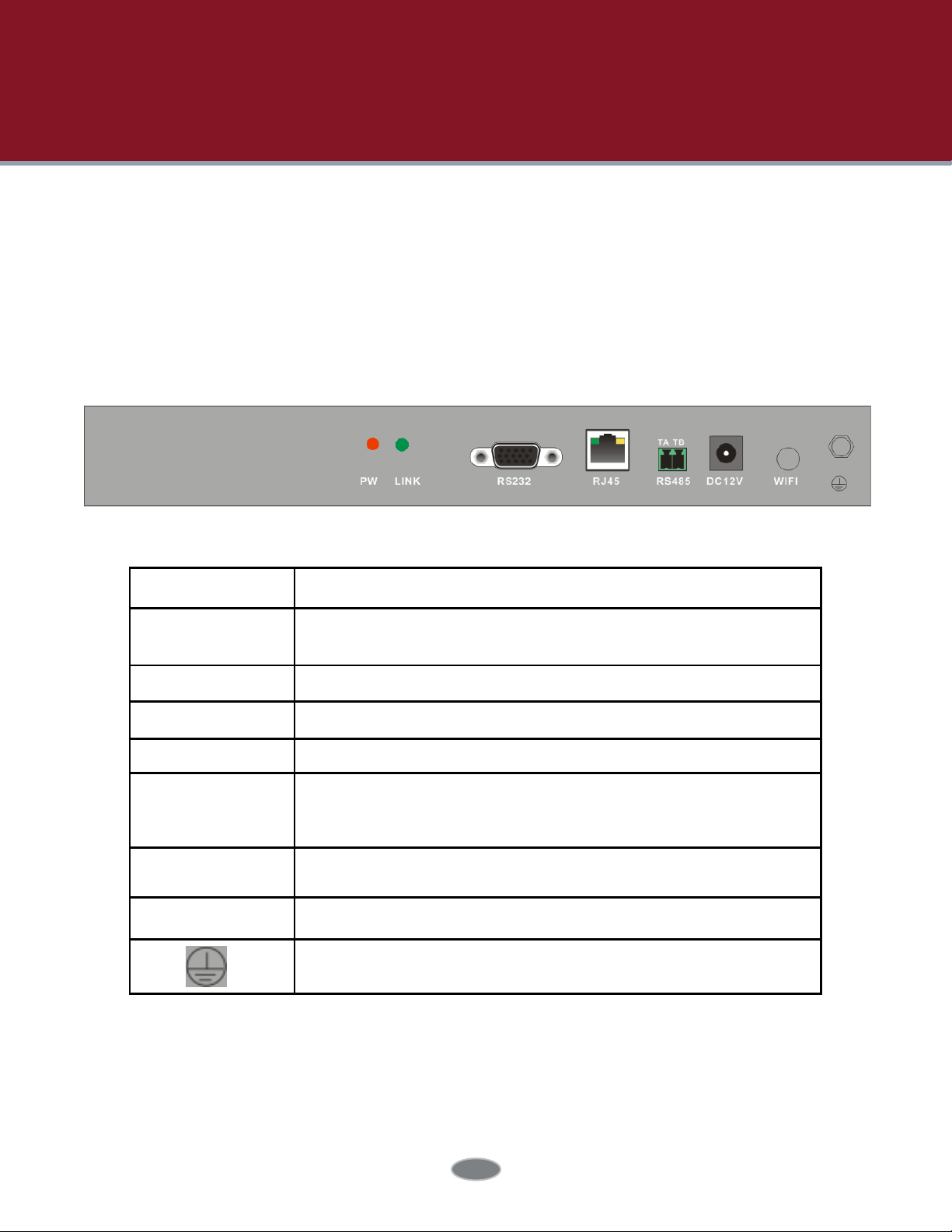
1.2 Rear Panel Instructions ................................................................................................................ 1
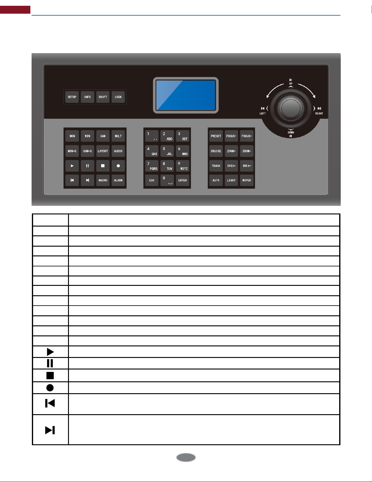
1.3 Front Panel Instructions ............................................................................................................... 2
1.4 Rules of Key Press ......................................................................................................................... 3
1.5 Joystick Control ............................................................................................................................. 4
2 Setup ........................................................................................................................................... 5
2.1 Startup the Keyboard ................................................................................................................. 5
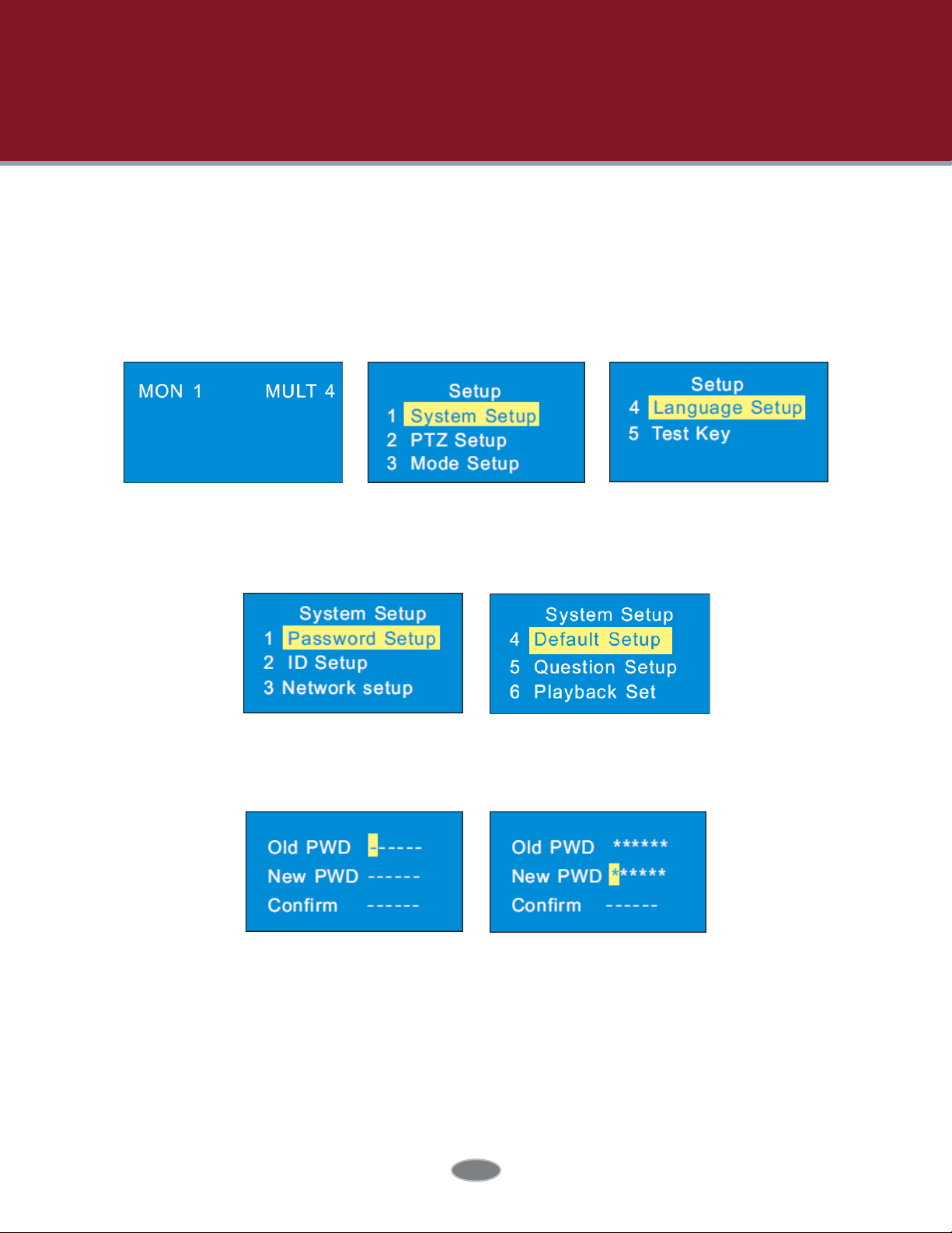
2.2 System Setup ................................................................................................................................ 5
2.2.1 Password Setup .......................................................................................................... 5
2.2.2 Keypad ID Setup ........................................................................................................ 6
2.2.3 Network Setup ............................................................................................................ 6
2.2.4 Default Setup .............................................................................................................. 7
2.2.5 Question Setup ........................................................................................................... 7
2.2.6 Playback Set ................................................................................................................ 7
2.3 PTZ Setup ........................................................................................................................................ 7
2.4 Language Setup .......................................................................................................................... 7
2.5 Test ................................................................................................................................................... 8
3 PTZ Mode .................................................................................................................................... 9
3.1 Mode Setup .................................................................................................................................... 9
3.2 PTZ IP Setup ................................................................................................................................... 9
3.3 PTZ Operation ............................................................................................................................... 9
3.4 PTZ Shift ......................................................................................................................................... 10
4 Decoding ................................................................................................................................... 11
4.1 Screen Display Mode ................................................................................................................. 11
4.2 Camera->Monitor....................................................................................................................... 11
4.3 Camera Group-> Window ...................................................................................................... 12
4.4 Camera Group->Monitor ........................................................................................................ 12
4.5 Call Layout.................................................................................................................................... 13
4.6 Set and Call Macro ................................................................................................................... 13
4.7 Alarm Window Setup ................................................................................................................ 14
4.8 PTZ Control .................................................................................................................................. 14
4.8.1 Move or Stop .............................................................................................................. 14
4.8.2 Set or Call Preset ..................................................................................................... 15
4.8.3 Call or Stop Cruise/Track ..................................................................................... 15

4.8.4 Focus +/- .................................................................................................................... 16
4.8.5 Zoom +/- ..................................................................................................................... 16
4.8.6 Iris +/-............................................................................................................................ 16
4.8.7 Start or Stop Auto Scan ......................................................................................... 17
4.8.8 Enable/Disable Light .............................................................................................. 17
4.8.9 Enable/Disable Wiper ............................................................................................ 17
4.9 Record Playback ........................................................................................................................ 18
4.9.1 Start Playback ............................................................................................................18
4.9.2 Pause Playback .........................................................................................................18
4.9.3 Play the Previous 30s ...............................................................................................18
4.9.4 Play the Next 30s or Frame ...................................................................................18
4.9.5 Stop Playback ........................................................................................................... 18
5 Others ........................................................................................................................................ 19
5.1 View Information .......................................................................................................................... 19
5.2 Lock ................................................................................................................................................. 19
6 Web ........................................................................................................................................... 20
6.1 Web Access ................................................................................................................................. 20
6.2 Upgrade ........................................................................................................................................ 21
7 Specifications .......................................................................................................................... 22
Appendix ..................................................................................................................................... 23
Network Keyboard Quick Start Guide

1 Introduction
1
DescriptionName
PW
LINK
RS232
RJ45
RS485
DC-12V
WIFI
When the network keyboard is working, the power indicator
turns red.
The network status indicator
Internal testing port
RJ45 network port
Connect speed dome or the RS485 port of the DVR; TA
connects to RS485+; TB connects to RS485-
DC12V power input
Unavailable
Grounding
1.1 Introduction
This network keyboard is fully compatible with the NVMS/CMS of our company, which can
control camera, screen, monitor, etc. It’s easy to use for users due to the menu display on
the screen.
1.2 Rear Panel Instructions

2
1.3 Front Panel Instructions
Introduction
FunctionsName
SETUP
INFO
SHIFT
LOCK
MON
WIN
CAM
MULT
MON-G
Local setup, such as keyboard ID, network setup.
Local information, such as ID, model, network parameters.
Auxiliary key for main interface shift or PTZ shift or security questions shift.
Lock keyboard; press this key to lock the keyboard.
Set the output (monitor).
Set the window of the current output.
Select the camera.
Set the screen display mode of the current output.
Select the output group (monitor group).
CAM-G Select the input group (camera group).
LAYOUT Call scheme.
AUDIO Enable/disable audio of the selected window.
Play
Pause
Stop
Enable / disable manual record.
Jump to the previous 30 seconds from the current playing time point by
clicking this button.
When the record is being played in the playback mode, it will jump to the next 30
seconds from the current playing time point by clicking this button; when the
record is on hold, the system will play the next frame by clicking this button.

3
1.4 Rules of Key Press
Double press--- the interval time between two presses less than 2 seconds. It mainly uses to
switch the alphabet.
For example, press 2 twice to input A; press 2 three times to input B. Please see appendix for the
detailed rules of key press.
When selecting or switching the operating object, it usually starts with the number key and ends
with the corresponding functional key. Take the following as examples.
1+MON (press 1 and then press MON)—— select 1 output
123+CAM (press 1, 2, 3 and then press CAM)—— select 123 output
10+PRESET (press 1, 0 and then press PRESET)—— call preset 10
Macro function key; set and call macro instructions.MACRO
ALARM
0-9
ESC
ENTER
PRESET
CRUISE
TRACK
AUTO
FOCUS+
Set the first image of the current output as an alarm large image.
Input the number/ alphabet /symbol.
Cancel the number/alphabet; cancel the operation; return to the previous menu.
Enter menu or confirm to save the current settings.
Set and call the preset.
Call or stop the cruise.
Call or stop the track.
Enable or disable the auto scan.
Click it to have long focus.
FOCUS- Click it to have short focus.
ZOOM+ Zoom in
ZOOM-
IRIS+
IRIS-
WIPER
LIGHT
Zoom out
Iris increases
Iris decreases
Enable or disable wiper.
Enable or disable light.
Introduction

4
1.5 Joystick Control
Introduction
Figure Operation
Up
Down
Left
Right
Upper Left
Upper Right
Lower Left
Lower Right
Rotate Left
Rotate Right
Function
In PTZ control mode: control the speed dome
to move up.
In PTZ control mode: control the speed dome
to move down.
In PTZ control mode: control the speed dome
to move left.
In PTZ control mode: control the speed dome
to move right.
In PTZ control mode: control the speed dome
to move towards upper left.
In PTZ control mode: control the speed dome
to move towards upper right.
In PTZ control mode: control the speed dome
to move towards lower left.
In PTZ control mode: control the speed dome
to move towards lower right.
Zoom in
Zoom out

5
2 Setup
2.1 Startup the Keyboard
First connect the network cable to the keyboard and then connect the power. After
the device starts, please input the default password (8888) and then press “Enter” key to go
to main interface (see left figure). Press “Setup” key to go to the system setup menu
(see right two figures).
Input the old password by moving the joystick right one by one (the default password is 8888).
Select the new password by moving the joystick down and then input the new password as the
above mentioned method. Finally confirm the new password and press “Enter” key to save the
settings. If you want to change the inputted number, please move the joystick to current position
to change the current number. If you want to cancel the inputted number, you can press “0” for
two times. Press “Enter” key to save the new password. Press “Cancel” key to return to the previ-
ous menu.
2.2 System Setup
All system setup menus are as follow. You can move the joystick up or down to see all system
setup menus.
2.2.1 Password Setup
Select the password setup menu and press “Enter” key to go to password setup.

6
2.2.2 Keypad ID Setup
Select the keypad ID setup menu and press “Enter” key to go to keypad ID setup.
The eective value of the ID is from 1 to 32.
To set keypad ID, press digital number and enter key (eg. press 32 and then press “Enter” to set
the keypad ID at 32).
2.2.3 Network Setup
Network setup includes local IP setup, PLAT IP setup and PTZ IP setup. The local IP address, the
PLAT IP address and PTZ IP address must be in the same local network segment.
Local IP Setup
Select “Local IP Setup” and press “Enter” to go to local IP setup. You can set the local IP address,
subnet mask, default gateway, DNS server, alternate DNS and HTTP port.
Tips: Move the joystick right to set the IP address. Press “Enter” to save the settings and return
to the previous menu.
Subnet mask: select subnet mask and press “Enter” to set subnet mask. The default
subnet mask is 255.255.255.0.
Default GW: the default gateway is 192.168.1.1. Please input it according to the actual
network.
DNS server: the default DNS server is 8.8.8.8. Please input it according to the actual
network.
IP address: Select IP address and press “Enter” to set the IP address. The default IP
address is 192.168.1.201.
Setup

7
Setup
Alternate server: the default alternate server is 4.4.4.4. Please input it according to the
actual network.
HTTP port: the default http port is 4000. Please input it according to the actual network.
IP address: input the IP address of the TV Wall Client of the ECMS/NVMS 5000.
Port: the default port is 56789. The port must be the same with that of the TV Wall Client.
Name and password: the name and password must be the same with that of the TV Wall
Client.
Test: To test if the keyboard is online.
PLAT IP Setup
Select “PLAT IP setup” and press “Enter” to set the PLAT IP address.
PTZ IP Setup
Please see 3.2 PTZ IP Setup for details.
2.2.4 Default Setup
Select it and press “Enter” to restore the system settings to the default factory settings.
2.2.5 Question Setup
Select it and press “Enter” to set the security question which can reset your password.
2.2.6 Playback Set
Only some models support this function.
Select it and press “Enter” to set instant playback time when using the network keyboard to
control video output of the decoder.
2.3 PTZ Setup
Select it and press “Enter” to go to the settings of PTZ to set the speed of the PTZ.
2.4 Language Setup
Select it and press “Enter” to switch the language between English and Chinese. Some models
also support Polish, Hungarian, Italian and so on.

8
Setup
2.5 Test
Select it and press “Enter” to test if the button is available. User can also check if the silk-screen
on the button and display on the screen is consistent which is not use for operating equipment.

9
3 PTZ Mode
3.1 Mode Setup
Platform mode and PTZ mode are optional. Select PTZ mode and press “Enter” to select. Some
models may connect 256 PTZs and control PTZs which support ONVIF.
Tips: Some models support a default mode (platform mode or PTZ mode), namely it will restore
to the last working mode after restart. In PTZ mode, you only need to select operational PTZ, do
not need to choose the output and the window, and the other operations are similar to the
platform modes.
3.2 PTZ IP Setup
Go to Network Setup to select “PTZ IP Setup” and press “Enter” to go to select the PTZ. Then set
the IP address, port, name, password of the PTZ selected.
IP address: input the IP address of the PTZ. This IP address must be in the same local
network segment with the local IP address of the network keyboard.
Port: the default port is 80 (the http port of the PTZ).
Name and password: the name and password must be the same with that of the PTZ.
Test: To test if the PTZ is online.
Clear: To clear the information of the PTZ (Only some models support this funtion).
3.3 PTZ Operation
After setting up the IP address, port, name and password of the PTZ you can operate the PTZ by
joystick or PTZ controller keys. Please see 4.8 PTZ Control for more details.

10
PTZ Mode
3.4 PTZ Shift
Some models support shifting the PTZs by pressing “Number plus SHIFT”.
Select other PTZ and setup the IP address, port, name and password. Please see 3.2 PTZ IP Setup
for more details.
Press “SHIFT” to switch the PTZs of which the IP address is setup well.

11
Before using the network keyboard to control video output of the decoder, please make sure the
authentication server, media transfer server, storage server, alarm server and TV wall server of
the ECMS/NVMS5000 all starts and they are all connected well with the decoder.
Note: Here we only take platform mode as example. If you choose the same monitor(window or
camera), you can skip the steps of inputting the monitor(window or camera).
4.1 Screen Display Mode
At present, it is only to support 1/4/9/16 screen display mode.
To set the screen display mode
1. Input the monitor number (the output number) and then press “MON” key to call this output. For
example, input 1 and then press “MON” to select No. 1 output.
2. Input the number of the screen display mode and then press “MULT” to set the screen display
mode of the above output. For example, input 9 and then press “MULT” to set at 9 screens
display mode.
Note: * The eective value is from 1 to 999. The maximum number of the screen display mode of
TV wall client is 16 screens. As a result, the maximum of 16 screens can be called when controlling
TV wall client.
* When controlling the output, the number of the output of the TV wall client must be set
in advance. The way to set the output number is to drag the output window to the right hand in
the TV wall client interface and then right click the top of the small window to pop up a menu.
Then go to TV wall client -> Setup -> Channel-NO. Mapping to change the output number.
4.2 Camera -> Monitor
Select the input signal (camera) to the designated output and window.
1. Select monitor (output). For example, input 1 and then press “MON” to select NO.1 monitor.
2. Select screen display mode. For example, input 4 and then press “MULT” to select 4 screens
display mode.
3. Select window. For example, input 3 and then press “WIN” to select NO. 3 window.
4. Select camera. For example, input 3and then press “CAM” to select NO. 3 camera.
4 Decoding

12
As a result, you will see the image of NO.3 camera in NO.3 window and 4 screens display mode
will be seen in NO.1 monitor.
You can check the relationship between camera number and channel from ECMS/NVMS5000
(go to TV wall client -> Setup -> Channel-NO. mapping).
Note: The eective value of the camera is form 1 to 999999. When NO. zero camera is inputted, it
means to delete the input from the designated window. The eective value of the window is from
1 to the number of the current all split screens.
4.3 Camera Group -> Window
1. Select monitor (output). For example, input 1 and then press “MON” to select NO.1 monitor.
2. Select screen display mode. For example, input 4 and then press “MULT” to select 4 screens
display mode.
3. Select window. For example, input 3 and then press “WIN” to select NO. 3 window.
4. Select camera group. For example, input 2 and then press “CAM-G” to select NO. 2 camera
group.
Camera group settings: go to TV wall client -> Setup -> Create Channel Group to create channel
(camera) group and dwell time. Then click “Modify or Delete Channel Group” to add the channel
for this camera group. The eective value is form 1 to 999999.
4.4 Camera Group->Monitor
Select the output group (camera group) to the designated output monitor. If the camera
quantity of the camera group (m) is equal or less than the quantity of the output window (n), the
camera output will be all displayed in the current screen display mode. If m is greater than n, the
previous n cameras will be output to the n windows in sequence and then the remaining n
cameras will be output to the n windows in sequence after the dwell time is up until all cameras
of the camera group is displayed. After that, all cameras of the camera group will be played
again like that. The setting steps are as follow.
Decoding

13
Decoding
1. Select monitor (output). For example, input 1 and then press “MON” to select NO.1
monitor.
2. Select screen display mode. For example, input 4 and then press “MULT” to select 4 screens
display mode.
3. Select camera group. For example, input 2 and press “CAM-G” to select NO. 2 camera group.
4.5 Call Layout
You may set the input or output scheme in advance and then call it through network keyboard.
For example, input 1 and then press “LAYOUT” to select NO.1 scheme.
To set scheme: go to TV wall client and then drag the outputs to the right window. Next, set the
screen display mode and add the cameras for all outputs. Finally click “Save” to save the
scheme. The scheme will be saved at the bottom of the TV wall client. You can call the saved
scheme by inputting number and pressing “LAYOUT” on the network keyboard. The eective
value is form 1 to 9999.
4.6 Set and Call Macro
Macro is used to provide a shortcut to execute a group of consecutive actions. A macro includes
a maximum of 50 key orders. Macro instructions are saved in the keyboard. The setting steps of
macro are as follow.
1. Input the digital number and then press and hold “MACRO” key to set macro. For
example, input 2 and press “MACRO” key for more than 2 seconds to set NO.2 macro.
2. Input a series of keys. For example, input 1 and press “MON”, input 2 and press “WIN”,
input 2 and press “CAM”.
3. Press “Enter” to complete the macro setup.

14
Input digital number and then press “MACRO” to call NO. 2 macro instruction. Moving the joystick
down can display all information of this macro instruction. Press “ESC” key of the keyboard to
return to the main menu of the keyboard.
4.8 PTZ Control
Only when the PTZ is input to the window and there is not sequence display in this window, can
the PTZ control be eective—that is, the camera input to this window must be a PTZ device (or
speed dome).
4.8.1 Move or Stop
The setting steps are as follow.
1. Select the output (monitor). For example, input 1 and press “MON”.
2. Select the window. For example, input 3 and press “WIN”.
3. Control the speed dome/PTZ by moving the joystick. When moving the joystick back to the
original place, the speed dome stops moving.
4.7 Alarm Window Setup
You can set the designated window as an alarm window. The designated window is NO.1
window by default, which cannot be modified in case the designated window set by the user is
not existence. The setting steps are as follow.
1. Select the output. For example, input 1 and press “MON” to select NO.1 monitor.
2. Press “ALARM” key to set the designated NO.1 window (channel) as alarm window. If the current
NO.1 window (channel) has been set as alarm window, the alarm window will be
cancelled by the above operation.
Decoding

15
Note: The camera input to the above example of NO. 3 window must be a PTZ device (or speed
dome), or the calling is invalid. The eective value of the preset is from 1 to 255. The eective
value of the cruise is from 1 to 8 and. The eective value of track is from 1 to 4. If the calling number
is beyond the range, an invalid tip will be displayed on the screen.
4.8.2 Set or Call Preset
To set preset
1. Select the output. For example, input 1 and then press “MON”.
2. Select the window. For example, input 3 and then press “WIN”.
3. Set the position of the preset by moving joystick.
4. Press the digital number on the keyboard to select the number of preset. Then press “PRESET”
for more than 2 seconds to set the preset. For example, input 1 and then press “PRESET” for more
than 2 seconds to set the NO.1 preset.
To call preset
1. Select the output. For example, input 1 and press “MON”.
2. Select the window. For example, input 3 and press “WIN”.
3. Select the preset. For example, input 1 and press “Preset”.
4.8.3 Call or Stop Cruise/Track
To call cruise/track
1. Select the output. For example, input 1 and press “MON”.
2. Select the window. For example, input 3 and press “WIN”.
3. Select the cruise/track. For example, input 1 and press “CRUISE/TRACK”.
Decoding

To stop cruise/track
1. Select the output. For example, input 1 and press “MON”.
2. Select the window. For example, input 3 and press “WIN”.
3. Select the cruise/track. For example, input 0 and press “CRUISE/TRACK” or press
“CRUISE/TRACK” directly.
4.8.4 Focus +/-
To set focus +/-
1. Select the output. For example, input 1 and press “MON”.
2. Select the window. For example, input 3 and press “WIN”.
3. Press “FOCUS+”or “FOCUS-”.
4.8.5 Zoom +/-
To set zoom +/-
1. Select the output. For example, input 1 and press “MON”.
2. Select the window. For example, input 3 and press “WIN”.
3. Press “ZOOM+”or “ZOOM -”.
4.8.6 Iris +/-
To set iris +/-
1. Select the output. For example, input 1 and press “MON”.
2. Select the window. For example, input 3 and press “WIN”.
3. Press “IRIS+”or “IRIS -”.
16
Decoding
Table of contents
Other AVYCON Keyboard manuals