manuals.online logo
Brands
  1. Home
  2. •
  3. Brands
  4. •
  5. AVZ
  6. •
  7. Lawn And Garden Equipment
  8. •
  9. AVZ Cubola Summerlight User manual

AVZ Cubola Summerlight User manual

Popular Lawn And Garden Equipment manuals by other brands

Sunforce SOLAR user manual

Sunforce

Sunforce SOLAR user manual

GARDEN OF EDEN 55627 user manual

GARDEN OF EDEN

GARDEN OF EDEN 55627 user manual

Goizper Group MATABI POLMINOR instruction manual

Goizper Group

Goizper Group MATABI POLMINOR instruction manual

Rain Bird 11000 Series Operation & maintenance manual

Rain Bird

Rain Bird 11000 Series Operation & maintenance manual

Cub Cadet BB 230 brochure

Cub Cadet

Cub Cadet BB 230 brochure

EXTOL PREMIUM 8891590 Translation of the original user manual

EXTOL PREMIUM

EXTOL PREMIUM 8891590 Translation of the original user manual

Snapper 690179 installation instructions

Snapper

Snapper 690179 installation instructions

Exmark SAR481KA30 Operator's manual

Exmark

Exmark SAR481KA30 Operator's manual

Yazoo/Kees Z12 Operator's manual

Yazoo/Kees

Yazoo/Kees Z12 Operator's manual

Makita EM408MP Original instruction manual

Makita

Makita EM408MP Original instruction manual

Exmark Quest Bagger Setup instructions

Exmark

Exmark Quest Bagger Setup instructions

Manitou Systems AS960 Operator's manual

Manitou Systems

Manitou Systems AS960 Operator's manual

Vertex 1/3 HP Maintenance instructions

Vertex

Vertex 1/3 HP Maintenance instructions

GHE AeroFlo 80 manual

GHE

GHE AeroFlo 80 manual

Land Pride Post Hole Diggers HD25 Operator's manual

Land Pride

Land Pride Post Hole Diggers HD25 Operator's manual

Yazoo/Kees Z9 Commercial Collection System Z9A Operator's & parts manual

Yazoo/Kees

Yazoo/Kees Z9 Commercial Collection System Z9A Operator's & parts manual

Premier designs WindGarden 26829 Assembly instructions

Premier designs

Premier designs WindGarden 26829 Assembly instructions

Snapper 1691351 installation instructions

Snapper

Snapper 1691351 installation instructions

manuals.online logo
manuals.online logoBrands
  • About & Mission
  • Contact us
  • Privacy Policy
  • Terms and Conditions

Copyright 2025 Manuals.Online. All Rights Reserved.

Cubola Summerlight EN 26-04-2017
Manufacturing and installation instruction
Cubola® Summerlight®
Terrace Awning
Cubola Summerlight EN 26-04-2017 page 2
* * A T T E N T I O N * *
AVZ accepts no liability for any errors in this manual,
or for any damage or losses resulting from the use thereof
NOTE:
The calculation method of the system has been changed to make it easier to
determine the cut sizes for connected systems.
All sawing measures are now based on the centre-to-centre measures of the bottom
supports.
NOTE:
The AVZ calculation configurator programme for the use of a single system is still
based on the outer measures of a single system!
Manufacturing instructions Cubola Summerlight®
Cubola Summerlight EN 26-04-2017 page 3
Dimensions (mm)*
Width unit
Projection unit
Height unit
Maximum per unit
4000 mm
4000 mm
3000 mm
* = While the system in theory allows for endless connection in all directions, it is not possible to end both front
profiles at one profile.
Note: No joints are available for the fabric rollers, so each unit of max. 4000 x 4000 mm has 2 motors.
Fabric winding method
The fabric of the Cubola Summerlight is wound bottomwise.
The fabric in the front beam is wound topwise (max. 800 mm projection).
Motor diagram
The values below apply to the awning fabric (roller 78).
Width
Projection
150 - 300 cm
300 - 375 cm
376 - 400 cm
200 - 250 cm
25 Nm
35 Nm
40 Nm
251 - 325 cm
25 Nm
35 Nm
40 Nm
326 - 400 cm
25 Nm
35 Nm
40 Nm
For the fabric in the support beam (valance) use at least 15Nm without fabric stretch compensation or 30Nm with
fabric stretch compensation.
Manufacturing instructions Cubola®Summerlight®
Cubola Summerlight EN 26-04-2017 page 4
Determine the centre-to-centre measure of the legs
In order to determine the cut sizes, first measure the centre to centre size of each unit. A drawing with dimensions is
shown below.
For a more detailed view, see the cut size diagram and the enclosed cut lists.
Note: Mounting plates extend beyond the width and projection sizes. This is 5 mm for the wall mounting plate and
45 mm for the mounting plate of the leg.
Dissimilar units
Note: In case of a connected system with dissimilar units placed in front or alongside one another, the outer size
minus the values are stated above are divided over the number of units.
For example: Freestanding model with 2 units connected in width:
Total width = 7000 mm
The total CTC size is then 7000 –110 mm = 6890 mm
If the first unit has a CTC size of 3000 mm, that of the second unit will be
6890 –3000 = 3890 mm.
Cut sizes
The cut sizes apply to all configurations, including a connected or wall-mounted system. It is based on the CTC size
of each unit. The applicable sizes are listed in the cut size diagram shown on the following page.
Projection
CTC projection = projection - 110
mm
Projection
CTC projection = projection - 10 mm
C to wall = HOH projection –45
Width (excl. sketch plates)
Total CTC width = width - 110 mm
CTC width 1
CTC width 2
Projection
CTC projection = projection - 110 mm
Supporting beam projection = CTC projection - 110 mm
Width
Height
Post = height –10 mm
Height above ground level
Depth below ground level
Ground level
Fabric projection=
CTC projection - 110 mm
Guide =
CTC projection - 330 mm
CTC width = width - 110 mm
Supporting beam/beam front = CTC width - 110 mm
Bottom cover = CTC width - 152 mm
Top cover = CTC width - 153 mm
Tube 78 = CTC width –194 mm
Fabric in cassette = CTC width - 282 mm
Front profile = CTC width - 302 mm
Front profile cover = CTC width - 303 mm
Fabric in supporting beam = CTC width - 190 mm
Roller 63 = CTC width - 160 / - 175 mm
Front frame = CTC width - 132 mm
Manufacturing instructions Cubola®Summerlight®
Cubola Summerlight EN 26-04-2017 page 5
Number and cut sizes
The cut sizes apply to all configurations, based on the CTC size of each unit. The number of units to be used is stated
in the table below.(Various cut sizes are enclosed).
Note: - You must determine the numbers of pieces for other configurations yourself.
- Use of dissimilar units will lead to different CTC sizes; this will result in multiple lengths for
one type of profile!
Freestanding (connected)
Wall-mounted ( connected )
Single
freestanding
Double
freestanding
side-by-side
Double
freestanding
following
Single wall-
mounted
Double wall-
mounted side-
by-side
Double wall-
mounted
following
CTC projection per unit
Projection –110 mm / no. of units
Projection –10 mm / no. of units
CTC width per unit
Width –110 mm / no. of units
Cut sizes Width
No. of pieces
Width beam
CTC width
–110 mm
1
2
1
0
0
0
Beam
CTC width
–110 mm
1
2
2
1
2
2
Front profile
CTC width
–132 mm
1
2
2
1
2
2
Roller 78
Somfy/ASA
CTC width
–194mm
1
2
2
1
2
2
Roller 63
Somfy/ASA
CTC width
–160 / –175 mm
1
2
2
1
2
2
Fr. profile
cover
CTC width
–303 mm
1
2
2
1
2
2
Front Profile
CTC width
–302 mm
1
2
2
1
2
2
Bottom cover
CTC width
–152 mm
1
2
2
1
2
2
Top cover
CTC width
–153 mm
1
2
2
1
2
2
Water cap
(option)
CTC width
–153 mm
(1)
(2)
(2)
(1)
(2)
(2)
Cut sizes Projection
No. of pieces
Projection
beam
CTC projection
–110 mm
2
3
4
2
3
4
Guide
CTC projection
–330 mm
2
4
4
2
4
4
Gutter
(option)
CTC projection
–250 mm
(2)
(4)
(4)
(2)
(4)
(4)
Cut sizes Height
No. of pieces
Leg
Height + measure below
ground level –10 mm
4
6
6
2
3
4
Fabric size
No. of pieces
Fabric in
cassette
CTC width
–282 mm
1
2
2
1
2
2
CTC projection
–110 mm
Fabric in
beam
CTC width
–190 mm
1
2
2
1
2
2
Fixed size
= 800 mm
Manufacturing instructions Cubola®Summerlight®
Cubola Summerlight EN 26-04-2017 page 6
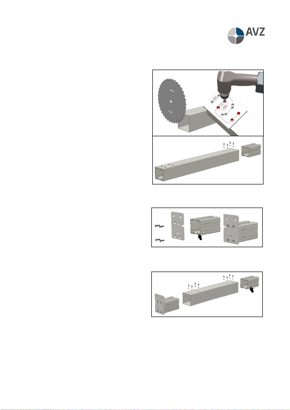
Beam assembly
This pre-assembly occurs several times, depending on the chosen Cubola Summerlight model. In case of a choice for
wall mounting, only wall-mounted beams will be provided (see next page).
a. Shorten the beam lengthways, cut off at right angle.
b. Place the drilling template and drill 4 holes
according to the 'beam' pattern. Do the same on the
other side of the profile.
c. Insert the corner mounting piece in the beam. Note:
Turn the side with the most holes towards the
centre of the profile so that the corner mounting
piece is laid 2 mm into the beam. N.B.: When the
profile is turned around, the corner mounting piece
will be flush with the profile. This is used for wall
mounting and thus not desired for this application!
If the beam is used for wall mounting, a corner
mounting piece will only be fitted to one side of the
profile. A wall mounting support will be fitted on site
to the other side of the profile.
d. Fasten the corner mounting pieces with the bolts on
the top.
Pre-assembly beam for wall mounting
In case of a choice for a wall-mounted system, the beams to be fitted against the walls will be provided with a wall
mounting plate.
a. Screw the wall mounting plate to the mounting
profile.
b. Note: 4 holes of the wall support should be directed
upward so that the outside of the profile is flush
with the end of the beam. The distance between the
wall mounting plate and the first holes is then 50
mm.
c. Slide the mounting profile into the tubular profile
(sawn and drilled as under beam pre-assembly).
d. Temporarily fasten the top of the wall mounting support or deliver the support separately with the profile.
First mount the support on site to the wall before attaching the beam.
e. Insert the other corner mounting piece into the
beam and fasten it.
f. Note: Turn the side with the most holes towards
the centre of the profile so that the corner
mounting piece is laid 2 mm into the beam.
N.B.: When the profile is turned around, the corner
mounting piece will be flush with the profile.
a
b
c
d
b
a
d
c
e
f
Manufacturing instructions Cubola®Summerlight®
Cubola Summerlight EN 26-04-2017 page 7
Pre-assembly front beam
a. Insert PVC inserts into the fabric and wind the
fabric topwise over the steel tube. Make sure that
the groove on the pull side is filed round so that
the fabric is not torn by being pulled against the
sharp edge.
b. Insert bearing plug into the non-operating side of
the fabric roller.
c. Place the motor with friction ring and motor plug
into the other side of the roller. Take the direction
of rotation into account.
d. Attach the mounting profile front piece to the
endplates of the beam, place the motor support
and fit the assembly against the roller with motor.
e. Make sure that the motor cable is drawn through
the cable hole in the endplate Then fasten the
motor using a motor clamp or cotter pin
(depending on the choice of motor).
f. On the bearing side, attach the mounting profile
to the endplate and place the bearing pin with
washer.
g. Cut the front of the beam profile and the front
frame to the cut size.
h. Place the drilling template on the top of the
profile and drill 4 holes according to the 'beam'
pattern. Do the same on the other side of the
profile.
i. Slide the fabric roller fabric into the profile from
one side.
j. Fasten the mounting profile using the 4 bolts on
the top.
k. Slide the bearing side mounting piece into the
profile up to the roller. Fasten it.
l. Slide the sealing strip into the beam.
m. Slide the filed off fabric roller against the fabric
and wind up the fabric.
a
b
c
d
e
f
g
h
i
j
k
m
l
Manufacturing instructions Cubola®Summerlight®
Cubola Summerlight EN 26-04-2017 page 8
Pre-assembly leg
a. Cut the legs at the right cut size.
b. Place the drilling template on the profile and
drill 6 holes according to the 'top of leg' pattern.
c. 2 of the 6 holes are for the cable feed (lighter
colour in figure). To limit drilling, one can
choose not to drill these doles in all the legs.
d. Turn the profile 90° (quarter turn) and drill the
same pattern again. If the bottom leg is fitted
with beams on 3 sides (in case of a connected
system), the pattern must also be drilled on the
third side.
e. Place the drilling template against the
underside of the profile and drill according to
the 'underside of leg' pattern.
f. Also drill two holes on the other side. Preferably
drill the holes on the same side as the holes on
the top of the profile.
g. Fasten the mounting adjusting plate to the
mounting profile using countersunk bolts.
h. Place the leg on the profile and fasten the 4
bolts on the side. You can opt to first fasten the
adjusting plates to the mounting location
against the wall before placing the profile on it.
In that case the adjusting plate must be kept
separately.
i. Insert the adjusting plate mounting profile into
the top of the profile.
j. Temporarily fasten the mounting profile using 2
bolts and nuts or loosely fit the adjusting plate
mounting profile into the leg.
k. Loosely fit the cover plates and bolt into the
bottom plate or fasten them temporarily.
a
b
c
d
e
f
j
g
h
i
k
Manufacturing instructions Cubola®Summerlight®
Cubola Summerlight EN 26-04-2017 page 9
Guide assembly
a. Cut the guides at the right cut size.
b. Place the end cap of the Cubola Summerlight
front profile at the mounting position (at b, make
sure the front is flush).
c. Drill a hole of 6.5 mm through the end cap, so
that it can later be fastened at point g.
d. Also drill a hole at the same place on the back
side for fastening to the cassette (end cap can
also be used as template).
e. Slide the guide plate into the rear of the guide.
f. Slide the bearing block with bearing into the front
of the guide.
g. Place the end cap of the front profile around the
guide and fasten it on the side with a countersunk
screw (through the guide into the end bearing
block).
h. Place a clamping plate into the bottom of the
profile and fasten the end cap on the underside.
i. Turn a self-drilling screw into the top of the
profile. This ensures that the end is fastened
on all sides.
Gutter guide assembly (option)
a. Cut the gutter guides at the right cut size.
b. Cut the ridge at 100 mm from both ends until the
rejuvenations. Watch out not to damage the edges
of the profile, the saw-blade is very close!
c. Break the saw-cut part of the profile by using
pincers.
A. Always use this part. Also in combination with
a side cap (e.g. SolidScreen) for instance.
B. If no side cap is used, use this part to close off
the space between the support beam and the
guide.
d. Place the end cap gutter at both ends of the
profile.
e. Drill 2 holes of 4.5 mm at intervals of ± 500 mm
above one another on the drill lines in the profiles
for fitting to the guide. Then fasten the two profiles
into the side guide using self-drilling screws.
f
h
e
i
g
b
c
d
b
A.A.
A.
B.
Manufacturing instructions Cubola®Summerlight®
Cubola Summerlight EN 26-04-2017 page 10
Pre-assembly cassette
a. Insert PVC inserts into the fabric and wind the
fabric bottomwise around the steel roller 78 mm.
b. Place cord pulleys as far as possible at the ends of
the roller, and fasten them with hexagon sockets.
c. Place the bearing plug and motor with adapter
and friction ring in the roller.
d. Fasten the cords to the cord pulleys and make at
least three rotations topwise around the pulleys.
The required length of cord per side is determined
as follows: 2x the extension + 1.5x the width + 1
m.
e. Assemble the cassette by attaching the top cover
supports to the bottom cover profile.
f. Fasten the bottom sections of the motor support
and the bearing block to the inside of the top
cover supports.
g. Drill a hole through the rear cover a top cover
support and place a rushing for the cable feed.
Note: The cable is connected at the top of the
bottom support. So preferably drill at the top of
the cassette so that the cable cannot be seen
from below.
h. Place the bearing on the bearing plug and insert
the roller into the cassette.
i. Feed the motor cable through the hole (in rear
cover or top cover support) without the cable
becoming snagged.
j. Ensure that the cable is not in contract with the
cord pulley. It is also advised to feed the cord
underneath the motor to prevent damage to the
cable.
k. Place the top halves of the motor support and
bearing block and fasten them.
l. Attach the top cover support holder to the top
cover support by inserting a M10 bolt through the
bearing.
m. Fasten the top cover with a self-locking nut, but
not too tightly as this point must rotate.
n. Check that the cord pulleys are positioned in line
with the cord wheels of the top cover support. If
not, adjust the cord pulleys.
o. Place the top cover on the cassette and fasten it
with 2 plate screws
b
a
d
c
c
e
c
e
g
f
h
i
j
k
m
n
l
o