2 | Page
Table of Contents
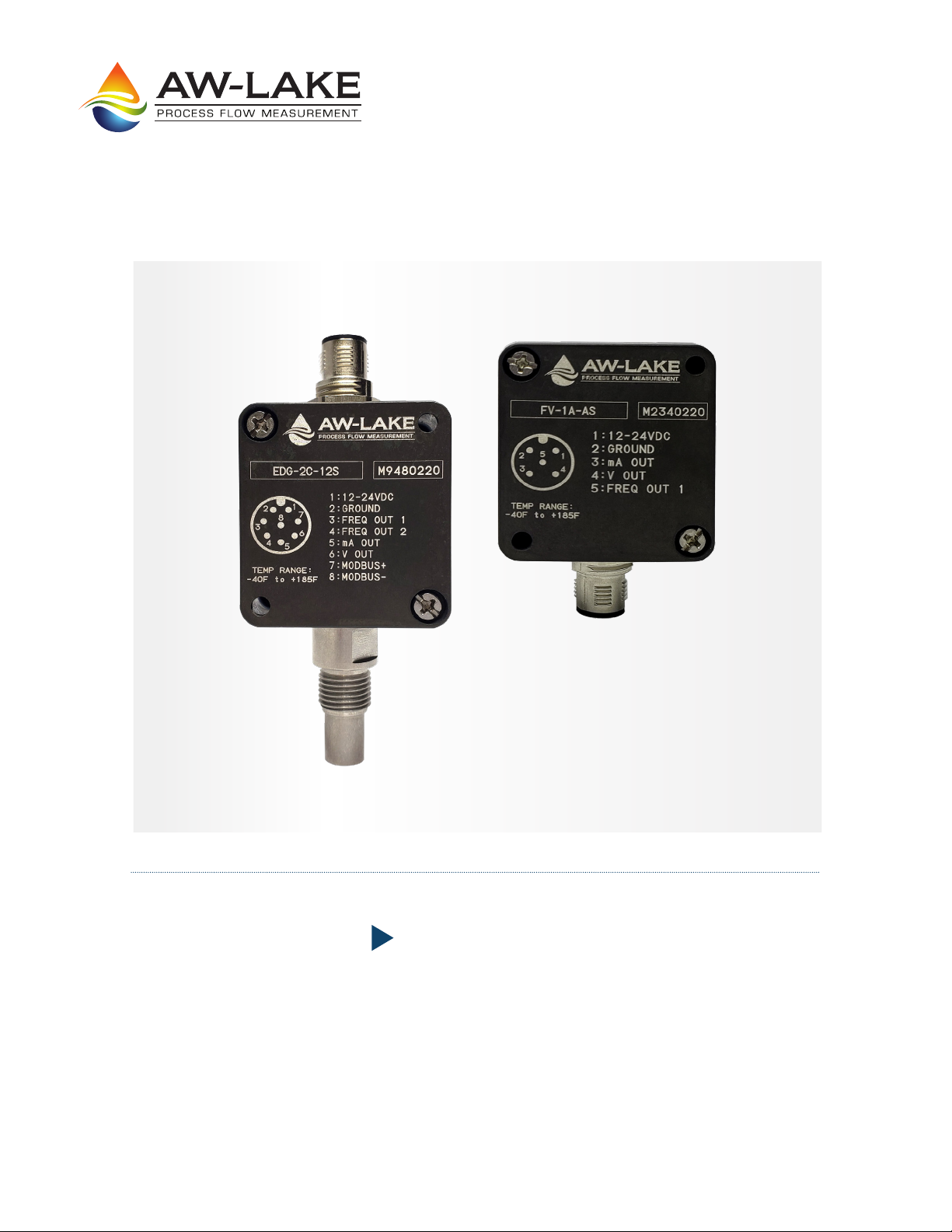
Product Overview.............................................................................................................3
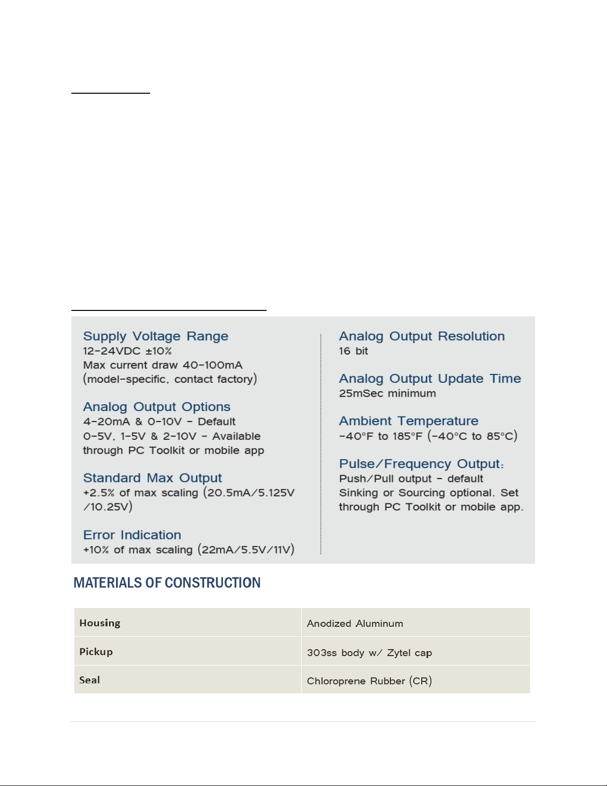
Technical Specifications ............................................................................................................ 3
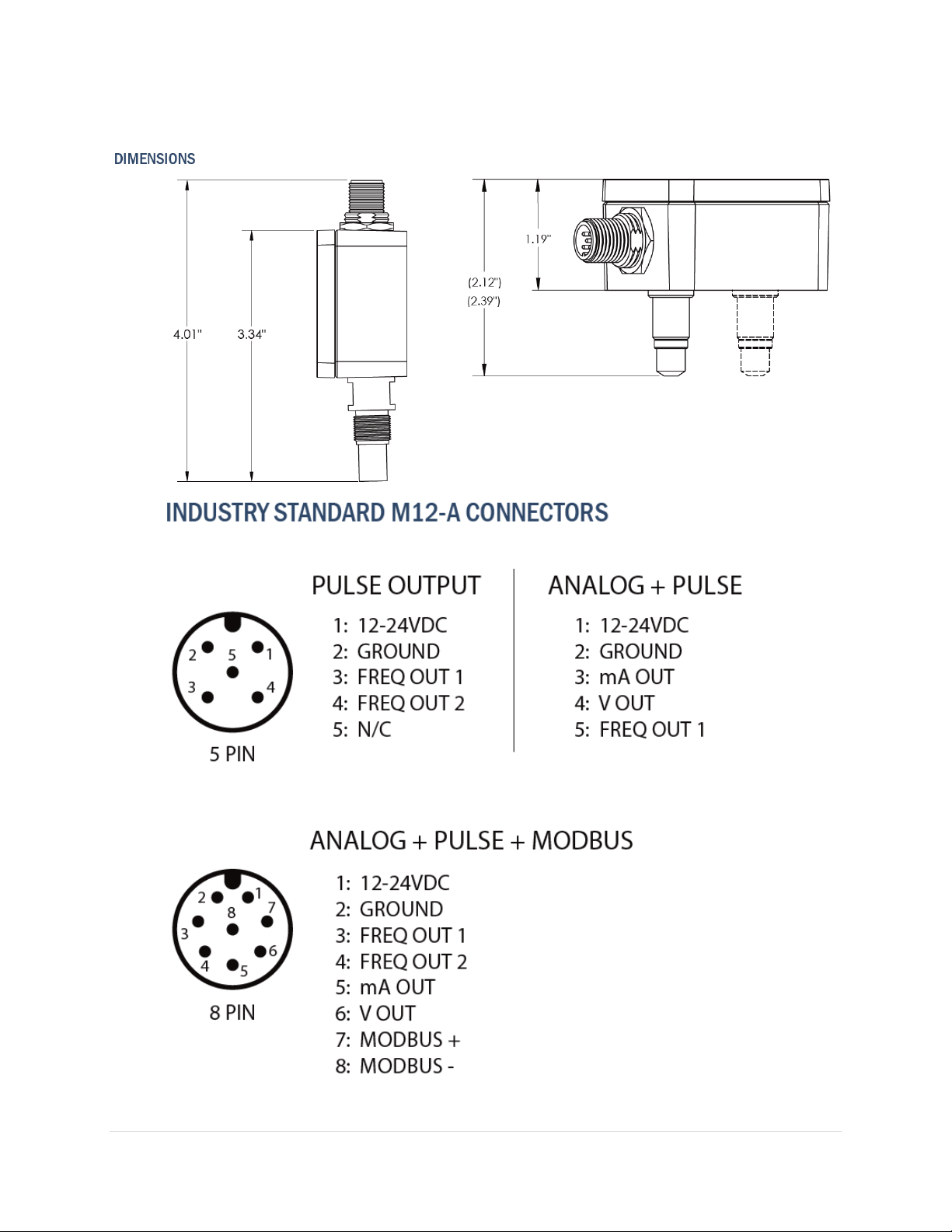
Dimensions................................................................................................................................ 4
Wiring Connectors .................................................................................................................... 4
Signal Information .................................................................................................................... 5
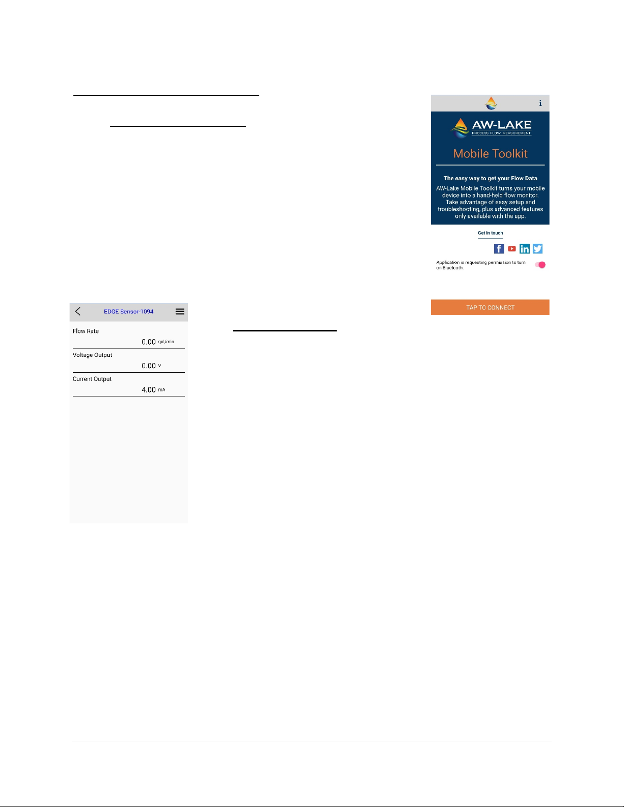
Bluetooth App .................................................................................................................6
Overview ................................................................................................................................... 6
Connecting ................................................................................................................................ 6
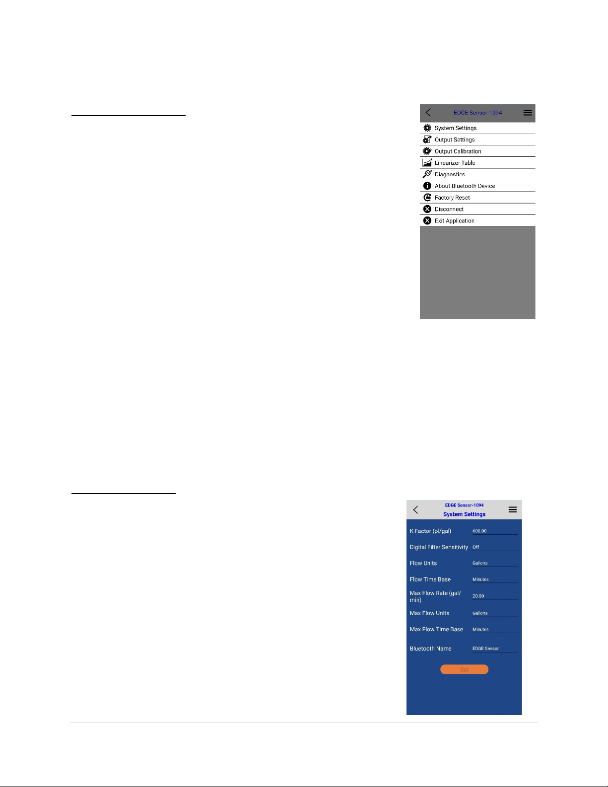
Menus ...................................................................................................................................... 6
System settings (Scaling units) ................................................................................................. 7
K-Factor .................................................................................................................................... 7
Max Flow Rate .......................................................................................................................... 7
Digital Filter .............................................................................................................................. 7
Time Base ................................................................................................................................. 7
Flow units.................................................................................................................................. 7
Bluetooth name ........................................................................................................................ 8
Output Settings ......................................................................................................................... 8
Forced outputs.......................................................................................................................... 8
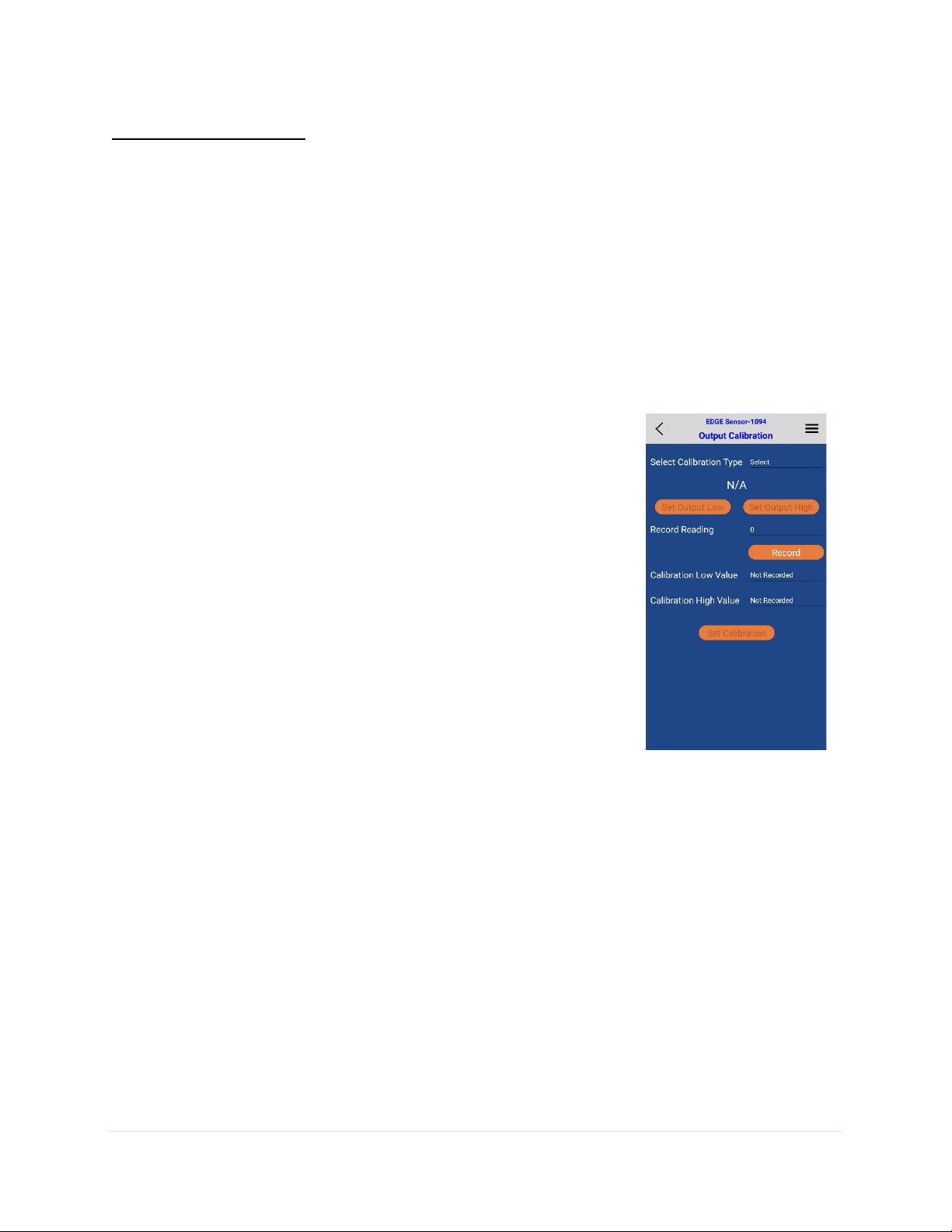
Output Calibration .................................................................................................................... 8
Linearizer................................................................................................................................... 9
Computer Toolkit ...........................................................................................................10
Overview ................................................................................................................................. 11
Getting Started........................................................................................................................ 11
Communication Status............................................................................................................ 11
K-Factor................................................................................................................................... 11
Scaling analog output.............................................................................................................. 12
Max Flow Rate ........................................................................................................................ 12
Digital Filter............................................................................................................................. 12
Time Base................................................................................................................................ 12
Flow units................................................................................................................................ 12
Analog Output Type................................................................................................................ 12
Forced Outputs ....................................................................................................................... 12
Analog Output Calibration ...................................................................................................... 13
Linearizer................................................................................................................................. 14
Bluetooth Settings .................................................................................................................. 14
Upgrading Firmware ............................................................................................................... 15
Modbus Register Map............................................................................................................. 16