BOTTARO WEIGHING SYSTEMS MB02 User manual


-
II
-
FILENAME : mb02 rev.4 rel 1.16
This publication may contain information with typographic errors. Corrections will be included in new editions of
the publication.
Edition dated 26/02/2014- Rev.“0”

-
III
-
FILENAME : mb02 rev.4 rel 1.16
1. INTRODUCTION 2
1.1
UNINTENDED USES 2
1.2
SAFETY 3
1.3
CARE AND MAINTENANCE 3
2. TESTING AND INSTALLATION 4
2.1
Testing and storage 4
3. INTRODUCTION 5
3.1
Description 5
3.2
LED indicators 6
3.3
List of selectable functions 7
4. USING THE TERMINAL 8
4.1
Message on startup 8
4.1.1
Displaying 1/10 e 8
4.1.2
Multi-division function (MD) 9
4.1.3
Multiple range weighing function (MR) 10
5. INTERFACES 11
5.1
Maxidisplay repeater device 11
5.1.1
Maxidisplay cable connection 11
5.1.2
Transmission string format 11
5.2
Input connection diagram 12
5.3
Rear panel 14
5.4
Loading cell connector 15
5.5
Metric plate location 16
Table of Contents
-
1
-
FILENAME : mb02 rev.4 rel 1.16
INDEX OF SOME TERMS USED IN THE MANUAL FOR EASIER CONSULTATION:
e
=
minimum verification division
Max
=
maximum instrument capacity
Min
=
minimum capacity
n
=
number of divisions
Load receiver device
=
scale or structure
Absolute zero
=
instrument zero calibration (+/- 1/4 e )
Instrument
=
computerized device
Sample weight
=
mass to be used as a reference for calibration
G
=
gross weight
N
=
net weight
T
=
tare weight
PT
=
Pre-set tare weight
MD
=
abbreviation for "multi-division"
MR
=
abbreviation for "multiple range weighing"
Baud rate
=
serial channel transmission speed
Frame
=
transmission format
Lights
=
indicators (e.g., LED)
etc
=
etcetera
g
=
grams
kg
=
kilograms
g1
=
gravitational acceleration at the location where the instrument is
installed
g2
=
gravitational acceleration at the location where the instrument was
calibrated
s###
=
minute second
ms
=
thousandth of a second
=
note, important information or procedure
=
attention, information or procedure that, if not followed exactly, could
cause death or severe personal injury
=
mains socket
=
not approved function
Terminology
-
2
-
FILENAME : mb02 rev.4 rel 1.16
The purpose of the manual is to inform the operator of the fundamental criteria and indications for installation and correct use of the
instrument using illustrations and guided examples.
The equipment must be installed only by specialized personnel who must have read and learned the contents of this manual.
"Specialized personnel" refers to those individuals with training and professional experience
who have been expressly authorized by the Plant safety supervisor to install, use and maintain
the terminal.
During the design phase, particular care was given in order to be able to use the instrument according to European Standards,
fulfilling the requirements set forth in L.D. 29.12.1992 no. 517 that was modified with Legislative Decree no. 40 dated February 24,
1997. It is the user's responsibility to make sure that installation is compliant with the legislation mentioned above.
The installer shall be responsible for parametrizing and calibrating it according to the specific needs while strictly following the
indications above.
Tampering with the devices and use of the equipment by untrained individuals is forbidden. For
this purpose, the manual must be consulted and followed whenever operating on the installation
parameters.
In the event of any anomalies, contact your authorized service centre.
The information and illustrations below are updated as of the edition date shown on the cover. The technical information in this
manual is the exclusive property of the manufacturer and therefore it is forbidden to make copies or share the information contained
herein without the manufacturer's written authorization.
The edition date and document number identify the correspondence between the manual and the firmware installed.
According to its corporate quality policy, the manufacturer is committed to continuous improvement of its products. This could lead to
changes in system components without compromising its metrological characteristics.
If there is a difference between what is described in this manual and your equipment, contact your authorized service centre.
Unless otherwise agreed upon during the order process, the terminal or complete system you received must not operate on moving
machines or installations as it may not be possible to ensure weighing precision as specified in EN45501.
Anything not expressly described in this manual is to be considered improper use of the equipment.
Any attempt to tamper with the legal constraint points or change the programming parameters
related to the weight data and primary indications by the user or unauthorized personnel will
automatically void the warranty and will release the manufacturer of all liability regarding any
injuries or damage.
1.1 UNINTENDED USES
1. INTRODUCTION
-
3
-
FILENAME : mb02 rev.4 rel 1.16
1.2 SAFETY
The voltage is high enough to be life-threatening.
Maintenance and repairs done on electrical and electronic parts must only be performed by
qualified technicians, after having adopted suitable safety measures.
Strictly follow the electrical rating plate on the appliance. If it is missing or illegible, request it from your authorized service centre.
Tampering with the devices and use of the equipment by untrained individuals is forbidden. For this purpose, the manual must be
consulted and followed whenever using or maintaining the terminal.
The power supply for the equipment is single phase, from 230V + 10% - 15% and must be provided with an effective earth, making sure that
the equipotential earth is compliant with current regulations. Make sure there is not potential difference between the earth and neutral.
Failure to earth the equipment is an incorrect and dangerous use of the instrument.
The electrical supply line must be dedicated. If already existing, use the computer power line. When there is no stable line,
install a sine wave UPS or mains stabilizer.
If the terminal must be connected to other devices such as computers, etc. before hooking it up, unplug them from power.
The safety instructions contained in this manual are not intended to exclude other situations or
conditions that could be hazardous. Therefore, common sense, attention and caution are
important factors which cannot be made part of the machine and therefore must be followed by
the authorised person who uses it and performs maintenance on it.
If the system must be installed in areas where there is a risk of explosion, this must be indicated
in the order specifications. The standard equipment is not set up to operate in areas with a
potentially explosive atmosphere.
Before cleaning, the device must be unplugged from the mains.
Do not use harsh products (such as solvents). Use a cloth with detergent. Avoid liquid infiltrations
in the instrument. Dry with a soft cloth.
If the operating safety of the device is no longer assured, immediately shut it off, unplug it from the mains, store it in a safe place and contact
your authorized service centre. This could occur in the following situations:
The device shows visible signs of damage or tampering.
There is a visually obvious malfunction.
The device was stored for a long time in unsuitable conditions.
1.3 CARE AND MAINTENANCE

-
4
-
FILENAME : mb02 rev.4 rel 1.16
Each instrument produced and inspected is subjected to testing in order to ensure a functioning product with long life and, if provided,
legalized by an official from the Notified Body.
Upon receipt of the instrument, check for any damage that may have occurred during transport.
Carefully unpack the instrument. Keep the original packaging for any later transport or movement.
Store the instrument on a flat, solid and protected surface where there are no extreme changes in temperature and humidity and where
it is safe from possible tampering by unauthorized personnel.
Do not stack objects on it.
Caution is recommended when handling the instrument.
Store the instruments as they were received. Do not stack pallets or any other type of object on it.
2.1 Testing and storage
2. TESTING AND INSTALLATION

-
5
-
FILENAME : mb02 rev.4 rel 1.16
The instrument is an analogue to digital converter for loading cells built especially for an industrial environment.
Therefore its features allow operation in harsh conditions.
The instrument satisfies the requirements in International Recommendation EN45501.
For greater safety, the instrument is equipped with automatic tests and a diagnostics program that gives
the type of error.
It comes with either a table, wall or rack container. The control panel is splash proof with tactile sensation keys.
The visor is highly visible. Some information is highlighted with separate lighted indicators.
It is equipped with EMI/RFI radio frequency filters and optical isolation to ensure operation in harsh
environments.
The specific part of analogue / digital conversion is controlled with an integrated single - chip, suitably interfaced to
the microcontroller.
The type of conversion used is cascaded DELTA SIGMA modulation (2 channel). All gain adjustment and
zero filter functions are digitally controlled.
All electronic boards and instrument components ensure high quality.
It can be connected to any OIML R60 certified loading cell and is approved for single scale operation.
The instrument can be used individually or combined with other industrial equipment for various uses, some of
which are described below:
-
Weighing road and rail vehicles
-
Detecting weights within production lines
-
Weighing various products with different bench scale solutions (at floor level or elevated)
-
Weighing in automatic loading and/or dosing systems.
-
Weighing suspended loads (aerial weighing in the food industry, etc.)
-
Determination of mass for calculating a toll, fee, tax, bonus, penalty, remuneration, indemnity or similar
compensation, to determine price based on weight for direct sale to the public and for determining other factors
such as the quantity, parameters and characteristics related to mass.
-
Combination with data acquisition systems and computers
-
Management of coordination devices for weighing operations
-
Network connections for data transfer
-
Handling systems
-
With devices for automating the scale operation through automatic material handling.
3.1 Description
3. Introduction
-
6
-
FILENAME : mb02 rev.4 rel 1.16
1: Stable
This is on when the stable indication conditions are met as per parameters P06 and P07.
2: Central zero
This is lit in the interval around zero from -1/4 e to+1/4 e.
3: Min min
This is lit when the gross weight is negative or between 0 and 20 ereduced to 5 in applications for determining
a transport fee.
4: Non metrological data symbol
When lit, the data shown is not bound to metric verification.
3.2 LED indicators

-
7
-
FILENAME : mb02 rev.4 rel 1.16
Pressing the ZEROkey for two seconds will zero out the weight indicator with a precision of 0.25 e. When
the key is pressed, the gross weight displayed will be acquired as the new zero value as long as the following
conditions are met for 1 second:
a)
stable indication
b)
gross weight less than 2% (subsequent zeroing) of the F.S. around the calibration zero point. If out-of-
range, the display will flash for 3 seconds.
c)
no tare device is in operation
Please note: If the requirements above are not met, the display will show E n E.
The zero value acquired will not be saved in the event of a power outage.
Place the tare that must be acquired on the scale and wait until the value stabilizes.
When the T key is pressed, the gross weight displayed will be acquired as the tare weight as
long as the following conditions are met for 1 second:
a)
the indication must be stable
b)
the value must be greater than or equal to 1 e.
c)
the value must be positive
d)
the value must be less than the F.S.
e)
the preset tare device must not be in operation.
If points b, dand eare not met, the "Tare no" error message is displayed. When the weight is unloaded
the weight removed will be shown with the minus sign
Please Note: the tare value acquired will not be saved in the event of a power outage.
If there is a tare weight present, pressing the key will display the gross weight. When the key is pressed again,
the previous net weight will be displayed.
If there is a tare weight present (previously acquired using the T key), pressing the
key mentioned above will save it so that all weights that follow are performed removing the previously set tare
weight.
To remove the tare from the memory, just press the key again.
- Save tare key
GROSS/NET- Change display key
With the multiple range weighing (MR) function, upon automatic switching to the higher weight range, the
tare division value will be compared automatically to the division related to the range obtained.
T Key - Tare acquisition
Zero Key - Zeroing device
3.3 List of selectable functions

-
8
-
FILENAME : mb02 rev.4 rel 1.16
4.1.1 Display 1/10 e
The software version and the use ZONE will be displayed (for about two seconds).
The instrument has a device for which the 1/10 division can be displayed as long as the related parameter is
enabled.
Once the terminal has been programmed in this manner, during normal display the last digit on the weight display
(on the right) will remain off.
Pressing and at the same time activates the procedure and the last digit is lit up and is the value of
the 1/10 division.
This display will remain active for about 5 seconds after which the terminal will automatically return to the normal
weight display.
This function is only possible if it was enabled in the setup program.
U G A
4.1 Message on startup
4.
Using the terminal
-
9
-
FILENAME : mb02 rev.4 rel 1.16
Through internal programming you can enable the multiple division function in two weight ranges each with a
minimum verification division.
The instrument, whether loading or unloading, automatically updates the verification division to the value related
to the partial weighing range.
The drawing below illustrates the function for a multiple division application in three weight ranges:
0 kg Min2 = Max1 Max2
Resolution e1
Resolution e2
Min = 20 e1
Partial range 1
Partial range 2
Where Max1 =maximum capacity of the partial weight range defined by the division e1. Min1
=minimum capacity of the partial weight range defined by the division e1.
Tare acquisition
When a tare weight is acquired, the weighing always starts from the lower range, that is the one with the lesser
verification division.
A self-weighed tare value can be equal to Maxr minus e1.
Example: 3000 kg scale with two division ranges:
Partial range 1: 0 ÷ 1500 kg e1 = 500 g
Partial range 2: 1500 ÷ 3000 kg e2 = 1000 g
If a tare of 2500 kg is acquired, weighing starts with the division e1 (500 g), with Max1 equal to 1500 kg. Since
the full scale is 3000 kg, in this example, since the first range of 1000 kg is exceeded, only 500 kg remains in
the second range (e2 =1000 g) for arrive at full scale: 3500 kg (tare) + 1500 kg (first range) + 1000 kg (second
range) = 6000 kg.
The situation is illustrated in the figure below.
Tare = 2500 kg
If in multiple divisions the operating range is not signalled by acquiring a tare, it always restarts from the first
weighing range.
Entering tare weight (preset tare)
If a tare is entered, the maximum value of the tare may not be greater than the Max1value, which is the
maximum capacity of the first partial weighing field.
0 kg
1500 kg
3000 kg
1st range
1500 kg
e
1
= 500
g
2nd range
1000 kg
e
2
=1000 g
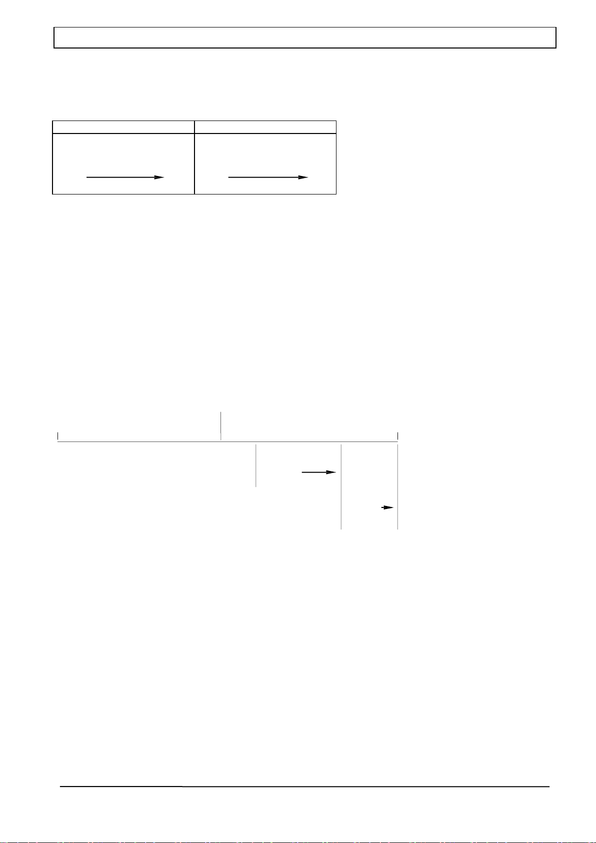
4.1.2 Multi-division function (MD)
-
10
-
FILENAME : mb02 rev.4 rel 1.16
Through par.18= 003 or 004 you can enable the multiple range weighing function, getting instruments with two
or more distinct scales, each having a range from zero to the maximum capacity. Each scale has its own
verification division and minimum capacity and is a distinct weighing range.
Switching from one weighing range to the next occurs automatically when the load exceeds the maximum
capacity of the lower range. This switching only occurs for increasing loads and the value of the higher division
reached is maintained in discharge until balance is reached with the instrument unloaded (zero). When this
condition is reached (meaning zero) switching occurs of the verification division compared to the minimum
division.
The drawing below illustrates the function for a multiple range weighing application in three weight ranges:
0 kg Max1 Max2= Max
Resolution e1
Resolution e2
Min1
Min2
Range 1
Range 2
Min1 = 20 e1 Min2 = 20 e2
Where Max1 =maximum capacity of the partial weight range defined by the division e1. Min1
=minimum capacity of the partial weight range defined by the division e1.
Acquiring and entering tare (preset tare)
For multiple range weighing instruments there is no limitation on entering the tare as in the multiple division
function. When entering a preset tare weight, upon automatic switching to the higher weighing range the value
is automatically transferred to the higher range and rounded to the value of the new division. The tare value,
which can either be acquired or entered, is equal to Maxr - er.
In multiple range weighing instruments using indication , notification is given of which weighing range
is being used.
4.1.3 Multiple range weighing function (MR)

-
11
-
FILENAME : mb02 rev.4 rel 1.16
The terminal can be programmed to control the Maxidisplay repeater device through a RS 485 serial
connection. This selection is made in the SERIAL PAR. menu under general programming that can be accessed
after pressing the setup key.
The parameters set by the manufacturer on the MB 01 (version 1.14) terminal are as follows:
APPLICATION PARAMETERS
Description
Baud rate serial channel RS 485
9600 baud rate
Data format
8/none/1
5.1.1 Maxidisplay cable connection
MAXIDISPLAY side MB01 EQUIPMENT side
9 way male 9 way female SERIAL 485
Pin no.
Description
Pin no.
Description
8
RXD
8
TXD -
6
RXD +
6
TXD +
Please Note: on the maxidisplay board, the J3 jumper must be between 1 and 2
The transmission string on the 485 serial channel can be transmitted only in Continuous mode and only on a
485 serial channel that is enabled for the Maxidisplay connection. The 11 digit string transmitted is as follows:
Num. of Digits
Description
meaning
1
$
Start char
2
space
3
1
4
1 dig weight
5
2 dig weight
6
3 dig weight
7
4 dig weight
8
5 dig weight
9
6 dig weight
10
7 dig weight
10
CR
End char
5.1.2 Transmission string format
5.1 Maxidisplay repeater device
5. Interfaces
-
12
-
FILENAME : mb02 rev.4 rel 1.16
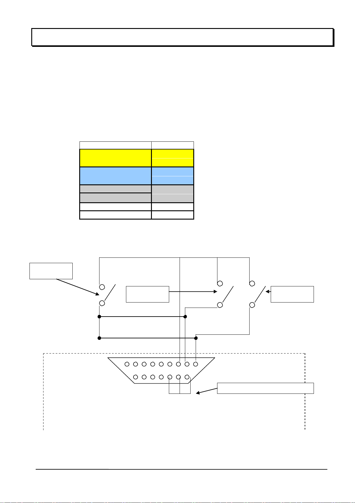
The terminal has two inputs that can be associated with various functions to be selected from among:
zeroing, tare acquisition, single printout and totals printout and are set in the setup area.
For proper operation 12 Vdc power supply is needed which can be external, from an external power supply as
long as it is stable and without disturbances, or inside the MB01 terminal as in the attached diagram.
Any external contacts must be at normally open "NO".
DB 15 male connector
Pin no.
Output no.
1
input 1
3
2
input 2
3
1 + 2
input 3
3
3
0 Vdc
11
12 Vdc
Example of connection between MB01 weight detection terminal and external systems:
Input 2
Input 1
Input 3
Connect PINS 9 10 11
DB 15 male connector
5.2 Input connection diagram

-
13
-
FILENAME : mb02 rev.4 rel 1.16
Appendix B Setting parameters note
PARAMETER
1
2
3
4
5
6
7
8
1
SCALE ADDRESS
Set value from 1 to 31
2
CONFIRM CE
NO
YES
-
-
-
-
-
-
3
CONVERSION TIME
Set value from 1 to 15
4
MEDIA CONVERSIONS
Set value from 1 to 32
5
STABILITY RANGE (e)
0
1
2
3
4
5
6
7
6
STABILITY TIME (s)
Set value from 0 to 4 (STEP 0.5)
7
ZERO TRACKER
Set value from 0.5 to 6.0 div
8
DISPLAY NEGATIVE
NO
YES
-
-
-
-
-
-
9
EXECUTION MODE
BENCH
SCALE
WEIGH-BRIDGE
No
printer
piece
counter
Eng. unit
-
-
-
10
USE ZONE
ZONE A
ZONE B
ZONE C
ZONE
SICILY 2
11
CALIBRATION ZONE
ZONE A
ZONE B
ZONE C
ZONE
SICILY 2
Installation parameters
Installation date:
....................................
Instrument S/N
....................................
Installer:
....................................
Installing co.:
....................................
Highlight the installation parameters and attach a copy to the instrument

-
14
-
FILENAME : mb02 rev.4 rel 1.16
The figure shows the layout of the external instrument connection in the table version:
Description:
INPUT VOLTAGE 12 Vdc
CONNECTOR FOR DIGITAL INPUTS
LOAD CELL CONNECTOR
SERIAL CHANNEL CONNECTOR 1 RS 485
1
2
4
3
5.3 Rear panel
1
2
3
4

-
15
-
FILENAME : mb02 rev.4 rel 1.16
To minimize electrical and radio interference, it is absolutely necessary that all connection cables
between the instrument and transducer are shielded and that the entire system is connected to an
excellent earth.
The instrument supplier can provide a specifically designed connection cable provided with double
shielding to be soldered to the shield terminals and the earth.
For the cable protection shielding connection, refer to the figure below.
DB 9 male connector
Pin no.
meaning
1
- POWER SUPPLY
2
- SENSE
3
Shield
4
+ SENSE
5
+ POWER SUPPLY
7
- OUT
8
+ OUT
External cable shield to tighten in
the metal cable clip with end burrs
to be tightened between the two
guards on the cap.
Cover shielded in
conductive material
End of the internal cable shield to
be tightened in the metal cable clip
Please Note: connect to pin 3 on
the connector
5.4 : Loading cell connector
-
16
-
FILENAME . mb01 rev.4 re/
1.16
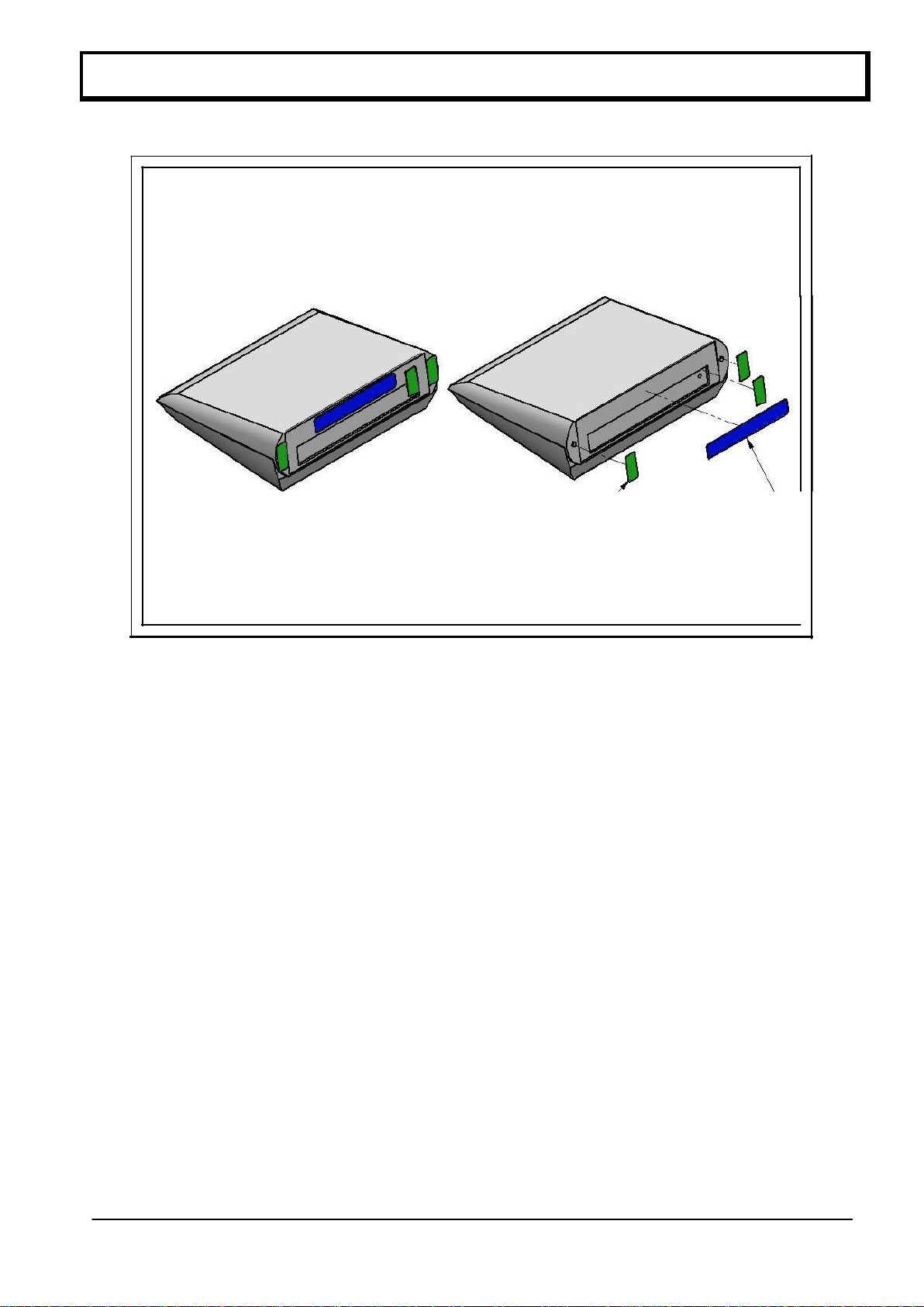
FIGURE A
FIGURE B
W3 CLOSING
FASTENERS
IDENTIFICATIONPLATE
5.5 Metric plate location
Table of contents
Popular Accessories manuals by other brands

Alutech
Alutech SDP Installation and operation manual

Wsky
Wsky AKZ-M4 quick start guide

NTI
NTI VOPEX Series Installation and operation manual

Kampa
Kampa DOMETIC RALLY AIR PRO 240 T/G user guide

Hella
Hella ONYX.TAG wind Installation instructions and instructions for use

Lithonia Lighting
Lithonia Lighting OALD 100MV 120 P LP installation instructions


