AW-Lake RT-50 User manual

Installation, Operating &
Maintenance Manual
RT-50 DC/Loop Flow Transmitter
©2022 AW-Lake Company. All rights reserved. Doc ID: RT50DCLOOPMAN060122

2
Table of Contents
Unpacking.....................................................................................3
Quick Start Guide...........................................................................3
Power ..........................................................................................3
Installation.....................................................................................3
Product Description................................................................................. 3
Technical Specifications...................................................................4
Part Number Guide.........................................................................4
Wiring Connections ................................................................................. 5
Power Supply .......................................................................................... 6
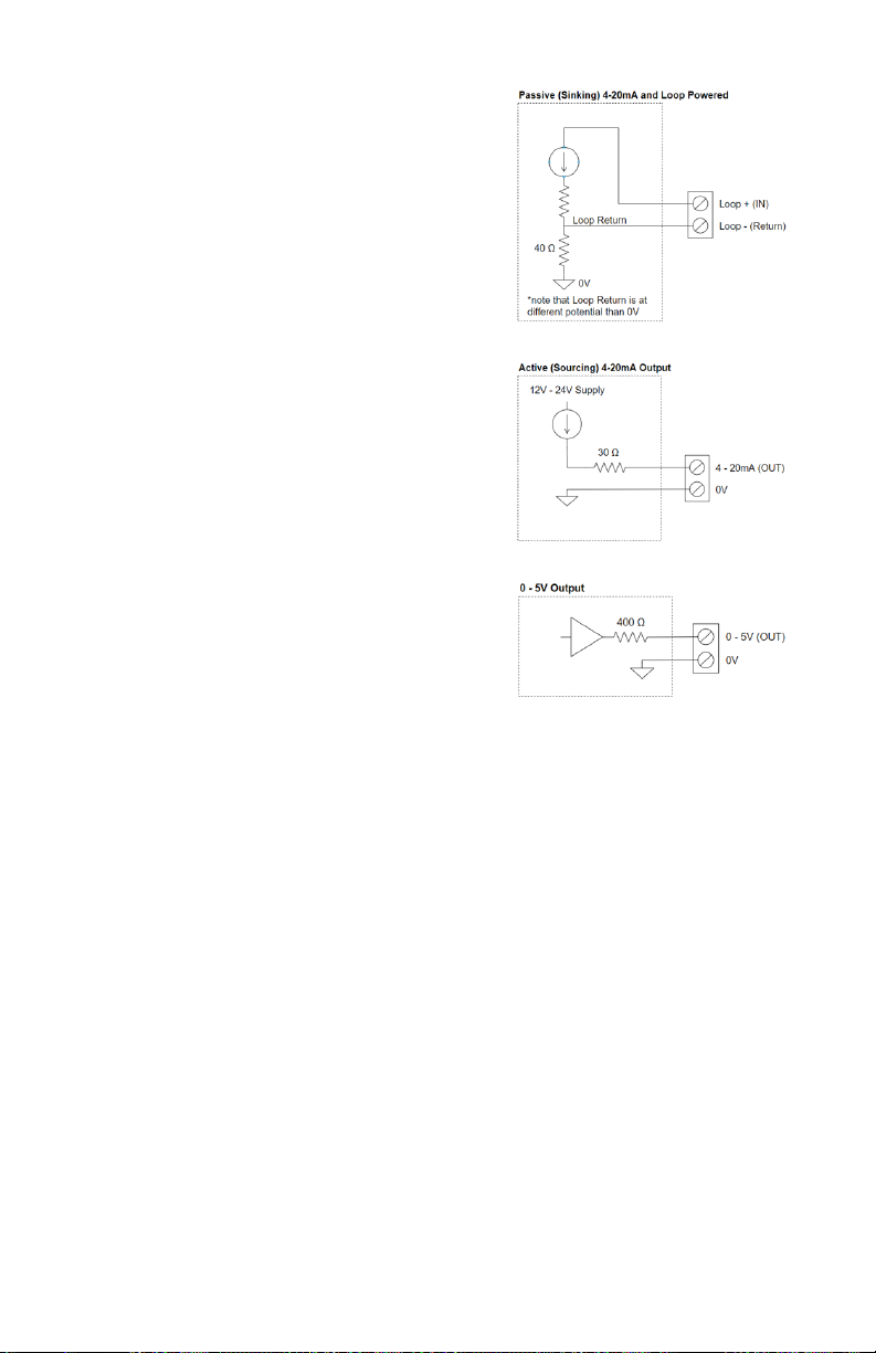
Isolated Outputs ...................................................................................... 6
Analog Outputs........................................................................................ 7
Navigational Buttons ............................................................................... 8
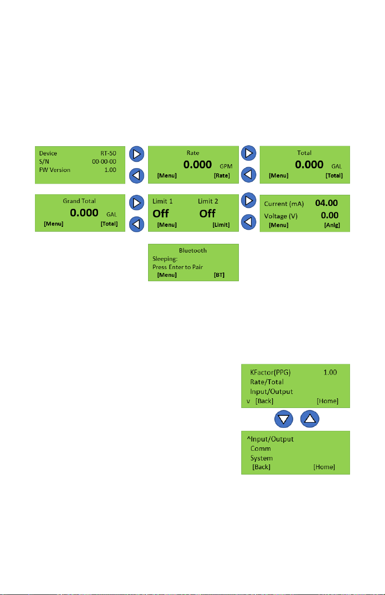
Run Mode Screens .................................................................................. 9
Menu Navigation ............................................................................9
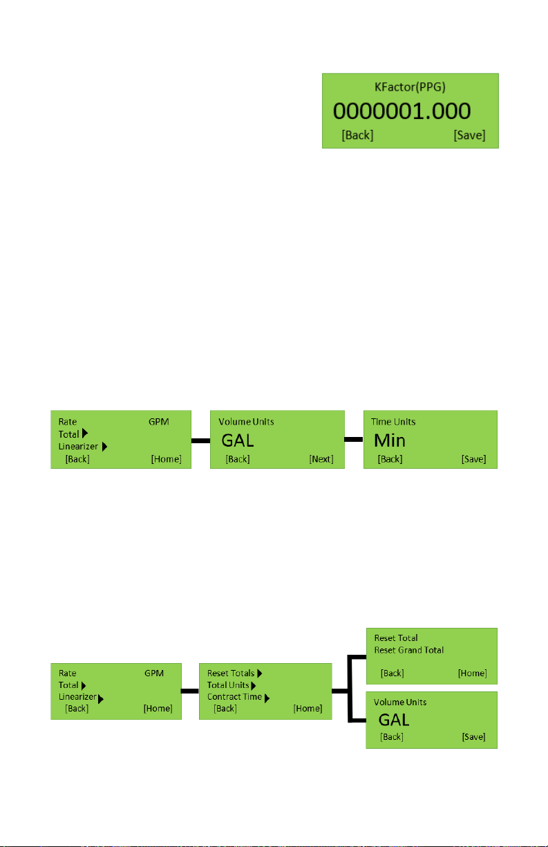
K-Factor......................................................................................10
Rate ...........................................................................................10
Total...........................................................................................10
Contract Time................................................................................11
Linearizer......................................................................................11
Input/Output.................................................................................12
System........................................................................................12
Bluetooth ............................................................................................... 13
Mobile Bluetooth App ............................................................................ 13
Menu Navigation ...........................................................................14
System Settings ............................................................................15
Output Settings .............................................................................16
Output Calibration..........................................................................16
Limit Settings................................................................................ 17
Linearizer.....................................................................................18
Device Log............................................................................................. 19
Date/Time Settings ................................................................................ 19
Compter Toolkit ..................................................................................... 20
Connecting..................................................................................20
Updating Firmware.........................................................................21

3
Unpacking
Separate the RT-50 Flow Display from packaging materials and check for any
visual signs of damage. If you determine there are damages caused by shipping,
file a claim with the shipping company. If the flow monitor appears to have been
improperly assembled or does not operate properly, Contact AW-Lake’s returns
department for replacement or repair.
Quick Start Guide
CAUTION: As with any precision-engineered device, always use the RT-50 in
accordance with the manufacturer’s instructions.
Power
Depending on version, the RT-50 can be powered with 24 Volts DC or can be
loop powered. Please check model number code to verify version type. For DC,
Power can be applied to pins 13 & 14. For Loop, apply power to pins 11 & 12.
See Page 5 for Connection details.
Installation
Secure display to flow meter by screwing sensor into designated sensor hole or
with proper fittings.
NOTICE: Before attaching the RT-50 to the flow meter, note any potential clearance
issues.
User must enter in the K-factor for the RT-50 before use. K-factors are found on
meter calibration sheet. For detailed instructions refer to programming instructions
in this manual. Once the K-factor is entered the unit is ready to read flow.
Product Description
The RT-50 flow display has the option to be powered by Battery, Loop, or DC
voltage. Showing Rate and Totals on an easy-to-read LCD display. With a new,
user-friendly menu structure, this unit is simple to setup and use. A new feature
with the RT-50 is, its Bluetooth capabilities. User can do the setup in the palm
of their hand and have a second display for checking flow information. The
basic function of this display is to read the incoming frequency from the attached
sensor and convert it to an accurate flow reading.

4
Frequency Output
Isolated output, matches sensor output
Linearizer
10-point programmable linearizer
Communication
Bluetooth and Modbus
Response Time
25 mSec
Housing Rating
NEMA 4X
Ambient Temperature
-4°F to +185°F (-20°C to +85°C)
Supply Voltage Range
24VDC or 4-20mA Loop
Analog Outputs
Lithium coin battery 3V. (CR2032)
4-20mA and 0-5V/1-5V
Limits
2 isolated limit outputs (24VDC Max)
Part Number Guide
RT–50–
–
Series
1 = TRG turbine and gear meters
(-60 & smaller)
2 = JV-80KL & -90KL gear meters
3 = TW & TR turbine meters
4 = High temperature
Power
D = DC powered
L = Loop powered
B = Battery powered
Sensor Type
C = Carrier frequency
(SS meters, TRG turbines)
M = Inductive (TR & TW turbine meters)
N = Inductive (Aluminum meters)
Sensor Mounting Thread
0 = Special mounting
3 = ½-20 UNF (TRG
turbines)
5 = M14 (gear meters)
7 = ½" TW collar
8 = ¾" TW collar
9 = 1" TW collar
Technical Specifications
LOOP POWER DC POWER BATTERY POWER
BT
BT decoupling
MODBUS
Isolated In/Out
I-OUT sourcing
I-OUT sinking
Hall Eect sensor (only when DC connected)
RF/IND sensor
V-OUT
Backlight
Options Based on Power Supply

5
Wiring Connections
Isolated Outputs
• Limit 2
• Isoltated Limit 1
• 0V
• Digital In
• Frequency Out
• 0V
• DC Voltage Input +
• DC Voltage
Power and Comms
• RS485 B
• RS485 A
• Loop + / I-out +
• Loop - / I-out –
• DC In + (Supply Power +)
• Ground (Supply Power -)
Sensor
• External 5V (Sensor Power +)
• Sensor Input
• Ground (Sensor Ground)
• 0-5 V Output
• Ground (Voltage Out Ground)

6
Power Supplies (Dependent on Variant)
DC Powered:
Voltage: 12 to 27V DC
Current: < 100mA
Loop Powered:
Voltage: 12 to 27V DC
Current: < 24mA
Isolated Outputs
The Isolated outputs require separate power.
Voltage: 12 to 27V DC
Current: < 10mA
Digital Input:
Input series resistance: 3.3 kΩ
Input Internal Pull-up resistance: 470 kΩ
Input Voltage: 3 – 12V
Input Frequency: < 10kHz
Isolated Input:
Input series resistance: 3.3 kΩ
Input Internal Pull-up resistance: 470 kΩ
Input Voltage: 3 – 12V
Input Frequency: < 10kHz
Isolated Output:
Output Configuration: Open Drain
Output Drain Current MAX: 100 mA
Output series resistance MAX: 6 Ω
Output Internal Pull-up resistance: 3.3 kΩ
Output Pull-up voltage: Connected Isolated
DC Supply Voltage

7
Analog Outputs
Passive 4-20mA (Sinking) and Loop
Powered
Loop Compliance Voltage: 12 to 27V
*Note that Loop Return is at different potential
to 0V
Active 4-20mA (Sourcing) Output:
Voltage on Output Terminal MAX: 12 to 27V
(DC Supply voltage)
Output series resistance: 30 Ω
0 – 5V Output:
Output series resistance: 400 Ω

8
Navigational Buttons
Left & Right Arrows
Allows user to switch between flow monitoring displays (ex. Rate, Total, Grand
total screen) Also allows user to move left and right when entering values.
Up & Down Arrows
Allows users to move up and down when in the menu structure. Also used to
increase and decrease values in programmable fields.
Enter
Used to Enter into a selected menu option.
F1
Dynamic button with 2 functions
• Gets user into Main Menu
• Go Back to previous menu
F2
Dynamic button with 3 functions.
• Quick Key to go directly into specific menus
• Saves user parameters
• Go Home to Main Screen

9
Run Mode Screens
There are 7 Run modes screens which include Home, Rate, Total, Grand Total,
Analog Out, and Bluetooth. To move from one screen to another simply press
the right or left arrow buttons. At the bottom of the run mode screens there are
two fast key options, F1 and F2. F1 gets you to the main menu and F2 takes you
directly to the programming parameter in the menu.
Note: Loop version does not have a limit screen but limits funcon the same.
Menu Navigation
The Main menu has 5 items. To move
between them, use the up and down arrows.
To go into the selected Menu press the
Enter button.
Note: settings will not take effect
until user presses SAVE
Figure 2
Figure 1

10
K-Factor
The K-factor is what links the flow display to
the meter. Each meter has a specific number
of pulses that equals a unit of measure, the
RT-50 uses pulses per gallon. In the main
menu press Enter on K-Factor (PPG) and
using the direction buttons enter in the k-factor
from the calibration sheet in pulses per gallon.
The decimal place does not move, so move over the necessary amount before
entering in the number. The right and left arrows move between numbers and the
up and down arrows will increase/decrease the number.
Rate
This menu allows the user to set the units and time base in which they would
like to read flow. The Rate and Total are independent of each other and must
both be changed if measuring in something other than gallons. With the selection
arrow on rate, press the Enter key. Use the up and down arrows to select your
units of measure and then press Next (F2). Now select the Time Base in the
same way a press Save (F2).
Total
This menu allows the user to set the units in which they would like to read the
total and grand total. It is also used to reset the total and grand total. The quick
key (F2) on the Total run mode screen takes you directly into the menu to reset
the totals. Once in the Volume Unit selection, use the up and down arrows to
choose desired units and press Save.
Figure 3
Figure 4
Figure 5

11
Contract Time
The Contract time allows the user to log totals and grand totals daily. The user
will designate a specific time in which they would like the totals to be logged.
The user also has the option for the display to automatically reset the total at
this time. Along with the Contract Time be sure to set the date and time in the
system menu. (see figure 6).
Linearizer
The linearizer is used when the flow meter has different K-factors throughout
the flow rate range. It allows the user to set up to 10 points, each with specific
frequencies and K-factors. This allows the user to measure more accurately
through the whole range. The calibration sheet included with the meter will tell
the user what frequencies correlate with each flow rate and the specific K-factor
that goes with it. To turn the linearizer On.
Note: For easier setup of the linearizer, users can program the tab le in the Bluetooth app.
Figure 6
Figure 7

12
Input/Output
The Loop and DC versions of the RT-50 have 2 isolated limit outputs, 4-20 ma
outputs, Voltage Output (DC version only), and an input filter. See page 6 for
wiring and circuit specifications.
Limits – Can be set to trigger from a Total, Grand Total, or Rate. When the
setpoint is reached the limit will trigger.
Input Filter – Allows the user to set filtering of the displayed flow rate. The filter
will steady the flow rate. Options for the filter include Off, High, Medium, and
Low. If the filter is set to Low, it will have the greatest effect on the rate changing
(Low response time).
System
In this menu, a user will able to adjust backlight settings, gate time, and Date/
Time.
Backlight - Can be set to stay on for a period of time between 1-3600 seconds
or can be turned off completely.
Gate Time - A feature similar to the filter, it allows a user to choose the amount
of time, in seconds, in which the display will update. For example if the gate time
is set to 3 sec, the device will only update the display every 3 seconds.
Date/ Time - User can input the current date and time. This is used when the
customer is data logging.
Figure 8
Figure 9

13
Bluetooth
This device is equipped with Bluetooth, allowing the user to read flow data and
set up the device via a mobile app. The Bluetooth menu is where a user can turn
Bluetooth connectivity on and off. It is also where a user changes the Bluetooth
name. Bluetooth is defaulted to enabled but is not always in pairing mode. To put
the device in pairing mode a user can press the Enter button on the Bluetooth
run mode screen (Figure 10) or in the Bluetooth menu under Pair BT. To disable
Bluetooth, press Enter on Bluetooth, press down to select disable, and press the
Save button.
Mobile Bluetooth App
First download the free app from the apple
or google play store. Before connecting
to the RT-50, the user must navigate to
the Bluetooth screen on the device and
enable pairing mode. This is done by
hitting Enter. User will then have 5 minutes
to connect to the device. Open the app,
turn on Bluetooth, and press Next button
to scan for available devices. Once found,
tap on the desired device which will take
the user to the device’s main menu. If a
device is not found, a user can scan again
by sliding their finger down from the top of
the screen.
*Location must be allowed to find a Device
Figure 10
Figure 11

14
Menu Navigation
Press the three lines in the top right corner to access menu
System Settings: Adjust K-factor, Max Flow Rate, Filter, Time Base, Flow Units,
and Bluetooth name
Output Setting: Allows user to change Analog Outputs and Force a specific
analog output.
Output Calibration: Allows user to slightly adjust analog outputs to better match
the system.
Limits: Allows user to set up limits to trigger by events related to rate, total, and
grand total.
Linearizer Table: Allows user to select custom K-factors for changing flow rates
Diagnostics: Shows raw input
frequency
Device Log: Shows daily Total and
Grand Total
Date/Time Settings: Allows user to set
real time and date
Display Settings: Allows user change
backlight settings and Gate time
About Bluetooth Device: Displays
device information
Factory Reset: Resets all user
parameters to default
Disconnect: Used to disconnect from
device
Figure 12

15
System Settings
This menu allows users to scale the RT-50
to display correct flow rate in the desired units
and time base. It will also allow for filtering of
the output.
*After any option is changed press SET for it to take
effect. Use back button on phone to return to main
screen.*
• K-Factor: is the flow meter scaling factor in
pulses/volume (found on calibration sheet)
• Digital Filter: Will smooth out erratic input
frequency. There are four options to choose
from;
• Off: No filtering
• Low: Most filtered, low sensitivity.
(Corner frequency ¼ Hz)
• Medium: Medium sensitivity.
(Corner frequency 1 HZ)
• High: least filtered, High sensitivity.
(Corner frequency 10 Hz)
• Flow Time Base: Can be set to Sec, Min, Hours, and Days.
• Flow Units: Selects what unit to measure flow in. Available units include;
Pulses, Ounces, Gallons, Barrels, Cubic Centimeters, Cubic Meters, Milliliters,
Liters
• Total Units: Selects what unit to measure flow in. Available units include;
Pulses, Ounces, Gallons, Barrels, Cubic Centimeters, Cubic Meters, Milliliters,
Liters
• Bluetooth Name: is the name that will appear when searching for the device.
Connection will be lost after changing the Bluetooth name and will require
reconnection. Device is limited to 12 characters. If more than 12 characters are
entered it could cause connectivity issues with the device.
Figure 13

16
Output Settings
Forced Outputs:
This menu will provide the option to force one
or both outputs to a certain value. Along with
this ability, Voltage output type will also be
selectable. (Figure 14) To activate, Move the
slider to the right. Enter in desired forced output
and press SET to store information.
*Note: Forced output will not output a value when
only being powered by USB. Information will not
be stored until SET is pressed and forced value will
revert back to previous value or state if output value
is outside of the range.
Forced Output Limitations:
When forcing an output, it must be in between
the analog out specifications and will go to the
third decimal place.
Ex. 4-20mA output Forced output: 6.25mA
Output Calibration
WARNING: Modifying these outputs could result in
inaccurate analog signals.
This menu is provided to adjust the EDGE
analog output to correspond correctly with the
analog output of the input device.
* This menu is intended for use with slight output
dierences between the EDGE output and customer
input device. These values are factory calibrated
before shipping to match meters that are calibrated
annually.
Select Calibration Type: From this menu both
mA and Voltage outputs may be calibrated.
(Figure 15)
Figure 14
Figure 15

17
1. Select which output type to be calibrated; mA or Voltage
2. Press Set Output Low, then enter in the value on user’s device into Record
Reading
a. Ex. If EDGE is being calibrated to a multimeter, enter reading from multimeter
to Record Reading
3. Press Record button
4. Now press Set Output High to calibrate the high end of the output
5. Enter in High reading from input device to Record Reading
6. Press Record button
7.
Verify both Calibration high and low values are correct and press Set Calibration
8. Use back button on phone to navigate to the main menu
*Warning do not do 2 calibrations in a row. After calibration is nished, exit the app and
restart the device.
Limits
The limit screen is used to set the parameters
that trigger the outputs. To use this function, set
the Input Source on the Output Settings menu
to Limit. The limit has 4 types of triggers: Rate,
Total, Grand Total, and Cycle Output.
Rate – Output will go high when flow rate is
within the given parameters and low when it
goes outside. Select a threshold/ target rate,
then select the percentage the flow rate that is
allowed to drift from that threshold. Example: a
10% bound on a threshold of 20 gpm would give
a rate range of 18-22 gpm.
Total – Output will go high when Total goes
above the threshold value.
Grand Total - Output will go high when Grand
Total goes above the threshold value.
Cycle Output – Output will change state between high and low every time the
threshold total is reached. To achieve one pulse per desired output, divide that
value by 2. For example, to get 1 pulse per gallon set threshold to 0.5 gallons.
*Cycle Output limited to 5Hz or 300 pulses per minute*
Figure 16

18
Linearizer
The linearizer function is designed to correct for
devices that will vary in a nonlinear way as a
device changes in flow/frequency. It can take
nonlinear input and change it to a more linear
analog output. There is a maximum of 10 points
that can be entered.
Ex. Looking at a meter that has a range of
0.5-2 GPM. If at 0.5 GPM (=100HZ) it has a
K-factor of 1800, at 1.5 GPM (=200Hz) it has a
K-factor of 1850, and at 2.0 GPM (=300Hz) it
has a K-factor of 1900. Using a linearizer would
ensure the most accurate results over the full
range of flow.
Entering Values:
*Values may only be entered and changed when Linearizer is Off*
Adding Values:
To enter in new values to the linearizer, press the “+” button at the bottom of
the screen. This will bring up a new window that prompts the user to type in a
desired frequency and corresponding K-factor. After values are entered, press
Add, this will input them into the table. If more values are needed, repeat this
step.
Editing Values:
To edit a value already in the table. Press on the value that needs changing and
enter in the new value. Do this for all existing numbers that need updating. To
save changed values press the Set button
Deleting Values:
To delete values in the table. Press the empty square next to the Index number.
This will be filled with a checkmark. Once all desired table values are selected,
press the “—” button, at the bottom of the screen, to remove the selected table
values.
Figure 17

19
Device Log
This menu is used in correspondence with
the Contract time located in the Date/Time
menu. A user can set a designated contract
time, and at this designated time the unit will
save the Total and Grand total in a table.
This menu allows the user to view those
results. The log will hold 29 values before it
starts to overwrite oldest entry. User will be
able to copy these values with a button on
the screen and paste it in other documents on
their phone.
*Note: When a factory reset is performed, log
values will be deleted*
Date/Time Settings
The Date and Time menu lets the user edit
the current date and time into the device. It
allows the user to enter in a Contract time,
which is the time at which the unit will record
totals into the device log. Remember to press
the Set button to update all changes made.
There is also an option to reset the Total at
this designated time. This will only reset the
Total and not the Grand Total.
Figure 18
Figure 19

20
Computer Toolkit
The Toolkit can be used to set up all parameter of the device and view flow
rates. This Toolkit also allows the user to update firmware as new releases
become available. In order to connect the RT-50 device to the computer a
separate cable will need to be purchased from AW-Lake Company. The Toolkit
can be found on our webpage under the Downloads tab or by following this link:
https://aw-lake.com/aw-lake-toolkit/
Connecting
After downloading and opening the software the user will see this connection box
appear (Figure 19). First select the correct COM port. If you are unsure which
COM port is being used, plug the USB cable in and out of the computer and
observe which COM port disappears from the pull-down menu. Next select the
device being used or click Auto-Detect Device on COM Port to open the device
configuration menu.
Figure 19
Table of contents
Popular Transmitter manuals by other brands

blukii
blukii Smart Key Go 500 manual

National Semiconductor
National Semiconductor VAB100T user manual

Cygnett
Cygnett CY-A-GSP quick start guide

Dwyer Instruments
Dwyer Instruments Magnesense MS Series Installation and operating instructions

SEA
SEA 23110550 manual

Definitive Technology
Definitive Technology SCW-100 owner's manual