Awaiba Dragster V3-8K-3.5 Use and care manual

Confidential
Confidential
Confidential
Confidential
DRAGSTER CONFIDENTIAL
DRAGSTER
Calibration
Revision : 0.0.04
Date : 25/06/09
Contact : AWAIBA GmbH
Am Weg eld 30
90427 Nurnberg
Germany
www.awaiba.com
1 Introduction
DATE: 25/06/09 DRAGSTER Evaluation
Version 0.0.04 PAGE: 1/6

Confidential
Confidential
Confidential
Confidential
Confidential
Confidential
Confidential
Confidential
DRAGSTER CONFIDENTIAL
This document gives a brie explanation about how to con igure the Dragster sensors in order to
reduce the e ects o the mismatch between pixel segments and to make the light response
linear or all sensor.
2 Setup
For this calibration the system will include an Eval board con igured as medium camera link, a
Dragster sensor V3-8K-3.5, the communication so tware DragsterComm and the rame grabber Me4
rom SiliconSo tware.
Although this calibration is made with a V3, the process is similar to the other versions.
3 Calibration
The inal goal o the calibration is to tune the ADC o set and gain error between segments so
than we get a uni orm image out o the sensor. For that 2 steps are necessary. One calibration step
without light and another with the light, pre erentially green (~ 520nm) at about 80% o saturation.
The image histogram is the guide over all the calibration process.
Be ore starting it's recommended to reset the sensor and sending the de ault values with the
DragsterComm. Check that rom pixels 4 to 7 there are the black and white re erence pixels and a ter
that only black pixels are present until the 63rd.
3.1 lack level calibration
The goal is to get both segment histograms right over 0 and one over the other.
DATE: 25/06/09 DRAGSTER Evaluation
Version 0.0.04 PAGE: 2/6
Confidential
Confidential
Figure 1: Image in light with default settings and no calibration.

Confidential
Confidential
Confidential
Confidential
Confidential
Confidential
Confidential
Confidential
DRAGSTER CONFIDENTIAL
Prevent any light o getting to the sensor by switching o the light and placing a black cap over
it.
Make a “Send All” o the de ault settings with DragsterComm. First we'll make a rough tuning
so that all segments show a histogram over 0. Once this is achieved a ine tuning o the individual
black levels has to be made so all histograms overlap and look like a single one.
Activate the image histogram. I it is clamped to zero, decrease the black level in “All
segments” and send this register. I both segments are ar away rom zero, increase the black level until
one o the histograms start getting close to 0.
A ter this the histogram should look like this:
Now the ine tuning has to adjust the higher histogram to go over the other. For this we need to
identi y which o them is the higher one. By setting a black level ± 10 o what was set in the Black
level All Segments it should be easy to identi y it.
Note: To set the black level o individual segments use only the 4K_1 SPI and 8K_1 SPI.
A ter the ine calibration, the black level should look like this:
DATE: 25/06/09 DRAGSTER Evaluation
Version 0.0.04 PAGE: 3/6
Confidential
Confidential
Figure 2: Initial black level

Confidential
Confidential
Confidential
Confidential
Confidential
Confidential
Confidential
Confidential
DRAGSTER CONFIDENTIAL
A ter this we should make the o set correction in order to use again all the ADC range,
otherwise the irst DN are wasted or the black signal and we'll never get pixels with values under what
was set. This should be made on chip using the Control 2 and Control 1 register. The next sequence is
the most adequate and although others might also work these steps are the sa est.
Using the “Send” buttons o the individual registers, ollow this sequence:
1. Start by making sure that in Control 1 "Subtract o set" bit is 0 and "Update request" to 1. Click
“Send”
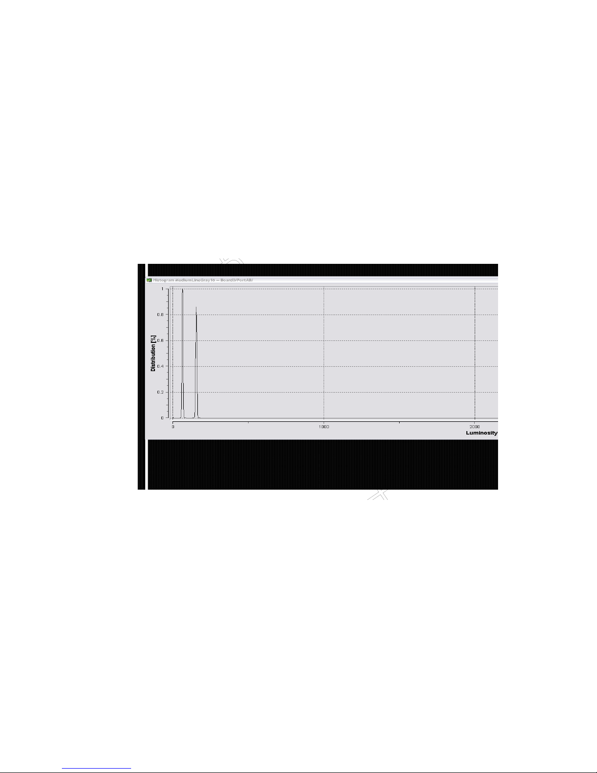
2. Set the sensor to dark condition and adjust the black level to the smallest output value over 0,
like described in this document. Avoid any pixel value o 4DN,i.e., the lowest ADC output
value.
3. Set in Control 2 "Write O set" bit to 1. Click “Send”.
4. Using Control 1 send the "Update request" on 1. Click “Send”. The image will ALWAYS
reeze, i.e, is not light sensitive, and the new acquired values are written to the internal o set
register. Looking at the histogram, i it did not reeze, the sequence has to be restarted.
5. Set in Control 2 "Write O set" bit to 0. Then “Send”.
6. Set in Control 1 "Subtract o set" bit to 1 and "Update request" to 0. Click “Send”.
7. Set again in Control 1 the "Update request" bit to 1 and click “Send”.
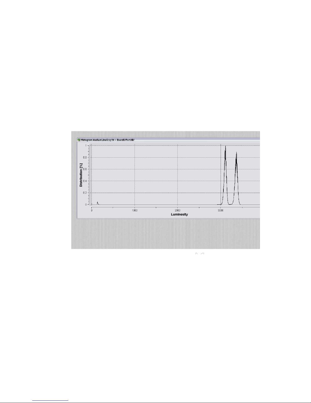
Now the dark image will be subtracted on chip rom the illuminated image.
When turning "Subtract o set" bit in Control 1 to 0 the stored o set image is lost and needs to
be reacquired with the same step sequence.
DATE: 25/06/09 DRAGSTER Evaluation
Version 0.0.04 PAGE: 4/6
Illustration 1: Black level calibrated

Confidential
Confidential
Confidential
Confidential
Confidential
Confidential
Confidential
Confidential
DRAGSTER CONFIDENTIAL
3.2 ADC Gain calibration
To calibrate the gain the best is to use a very stable light source with the possibility to regulate
the light energy. LEDs are recommended. Use the maximum light energy available or tune it so that the
histogram is between 3000DN and 3500DN
Set the sensor to the operating point, especially the gain programmed on the sensor to the
desired setting in your application. Tune the analogue gain on/o ( bit 5 Control 2) and the inverse
ADC gain register.
The histogram should look like this:
Use the 4K_1 SPI and 8K_1 SPI to ine tune the Inverse ADC gain o the individual segments.
Set again a value ±10 o what was set in the Inverse ADC gain o All segments so that we can identi y
which segment to tune.
Once the histograms are one over the other the calibration is done and the sensor shows a good
response over all range, just with the remark that the saturation level is not 4096 any more. Because the
on chip o set subtraction is activated, the ADC range is smaller.
As last step, the “End o range” register should be increased so that the ADC covers again a 12
bit range. In the Illustration 1 it's shown that the black level was set around 100DN so this is the value
that is recommended to be increased in the “End o range” register.
DATE: 25/06/09 DRAGSTER Evaluation
Version 0.0.04 PAGE: 5/6
Confidential
Confidential
Figure 3: Initial ADC gain calibration

Confidential
Confidential
Confidential
Confidential
Confidential
Confidential
Confidential
Confidential
DRAGSTER CONFIDENTIAL
DATE: 25/06/09 DRAGSTER Evaluation
Version 0.0.04 PAGE: 6/6
Figure : ADC gain calibrated
Table of contents
Popular Accessories manuals by other brands

Salus
Salus SS881ZB Installation and quick start guide

S+S Regeltechnik
S+S Regeltechnik Thermasgard ETF7 Series Operating Instructions, Mounting & Installation

Topcom
Topcom PB-5200 manual

MOVETEC
MOVETEC TBB9 user manual

KUSSMAUL
KUSSMAUL 091-22-100 installation instructions

Sunjoy
Sunjoy L-BC153PST-S Assembly instruction