Award DC1700EW User manual

DRYING CABINET
DC1700EW
GB
Before using this product,
please read the user manual
carefully. Save the user
manual for future reference.
User Manual

2
CONTENTS
THIS USER MANUAL 3
SAFE OPERATION 3
FOR A HEALTHY ENVIRONMENT 4
Packaging material 4
Disposing of a worn-out drying cabinet
4
COMPONENTS 5
Control panel 5
INSTALLATION 6
Unpacking 6
Reversing the door 6
PLACEMENT 7
Levelling 7
Securing to wall 7
VENTILATION/AIR SUPPLY 8
CONNECTING TO VENTILATION 8
With draft stabilizer 9
Direct connection to mechanical
extractor 9
ELECTRICAL SUPPLY 10
BEFORE USING THE DRYING CABINET
11
ARRANGING ITEMS FOR DRYING 11
User advice 11
Air ow 11
DRYING PROGRAMME 12
Programme 12
Programme selection 12
Control panel 12
CHILD LOCK 13
Switching child lock on/o 13
DRYING WITHOUT CHILD LOCK 14
Automatic programme 14
Manual programme 14
Pausing a programme 15
Stopping the drying phase 15
DRYING WITH CHILD LOCK 16
Automatic programme 16
Manual programme 16
Pausing a programme 17
Stopping the drying phase 17
THERMAL CUTOUT 18
CARE 19
Cleaning 19
Replacement parts 19
Servicing 19
TECHNICAL DATA 20
Energy consumption and drying times
20
WARRANTY 21

3
THIS USER MANUAL
The contents of this manual describe the
operation and use of the drying cabinet and
provide instructions for its installation and
maintenance.
_______________________________________
NOTE! Keep this user manual
handy, so that it is always available
for future reference.
______________________________________
SAFE OPERATION
This drying cabinet complies with the relevant safety requirements Incorrect
use can lead to injury and damage to property.
This advice on using the appliance safely is provided to help you avoid
incorrect use and unnecessary risks, and you should read it before installing
or using the drying cabinet
WARNING! This equipment is only intended for drying textiles that
are washed in water.
pThe drying cabinet must be installed and kept indoors.
pThe appliance is not to be used by persons (including children)
with reduced physical, sensory or mental capabilities, or lack
of experience and knowledge, unless they have been given
supervision or instruction.
pDo not let children play in, on or with the drying cabinet. Keep
an eye on children when they are close to the cabinet.
pCleaning and maintenance must not be carried out by children
without supervision.
pReplace the power cord immediately if it is damaged. The
power cord may only be replaced by the manufacturer, an
authorised service representative or a qualied electrician!
pFollow AWARD instructions when repairing and replacing
parts.

4
FOR A HEALTHY ENVIRONMENT
PACKAGING MATERIAL
The packaging that protects the drying
cabinet during transport was chosen with
the environment in mind and is therefore
recyclable.
By recycling packaging you reduce the use
of new resources and reduce the amount of
waste.
DISPOSING OF A WORN-OUT
DRYING CABINET
When the drying cabinet has reached the end
of its useful life it must be sent for dismantling.
Many parts can be recycled, but the cabinet
also contains materials that must be disposed
of correctly. So never dispose of the drying
cabinet or its components with general
household waste, as this could cause health
risks and harm the environment.
Send the worn-out drying cabinet to a
recycling station instead. Contact your retailer
for information if necessary.
All the plastic components of the drying
cabinet are marked with standardised
international symbols. These allow the parts to
be sorted correctly for recycling.

5
CONTROL PANEL
COMPONENTS
Buttons for selecting drying program
See page 12
Stop button
LEDs
Power cord
Damp air outlet
Air intake
Heater and fan components assembled
in a removable fan unit behind the
cover panel
Door hangers
Three sliding sets of hangers
Door, right-hung or left-hung
Shoe rack
Adjustable feet (4)

6
INSTALLATION _______________________________________
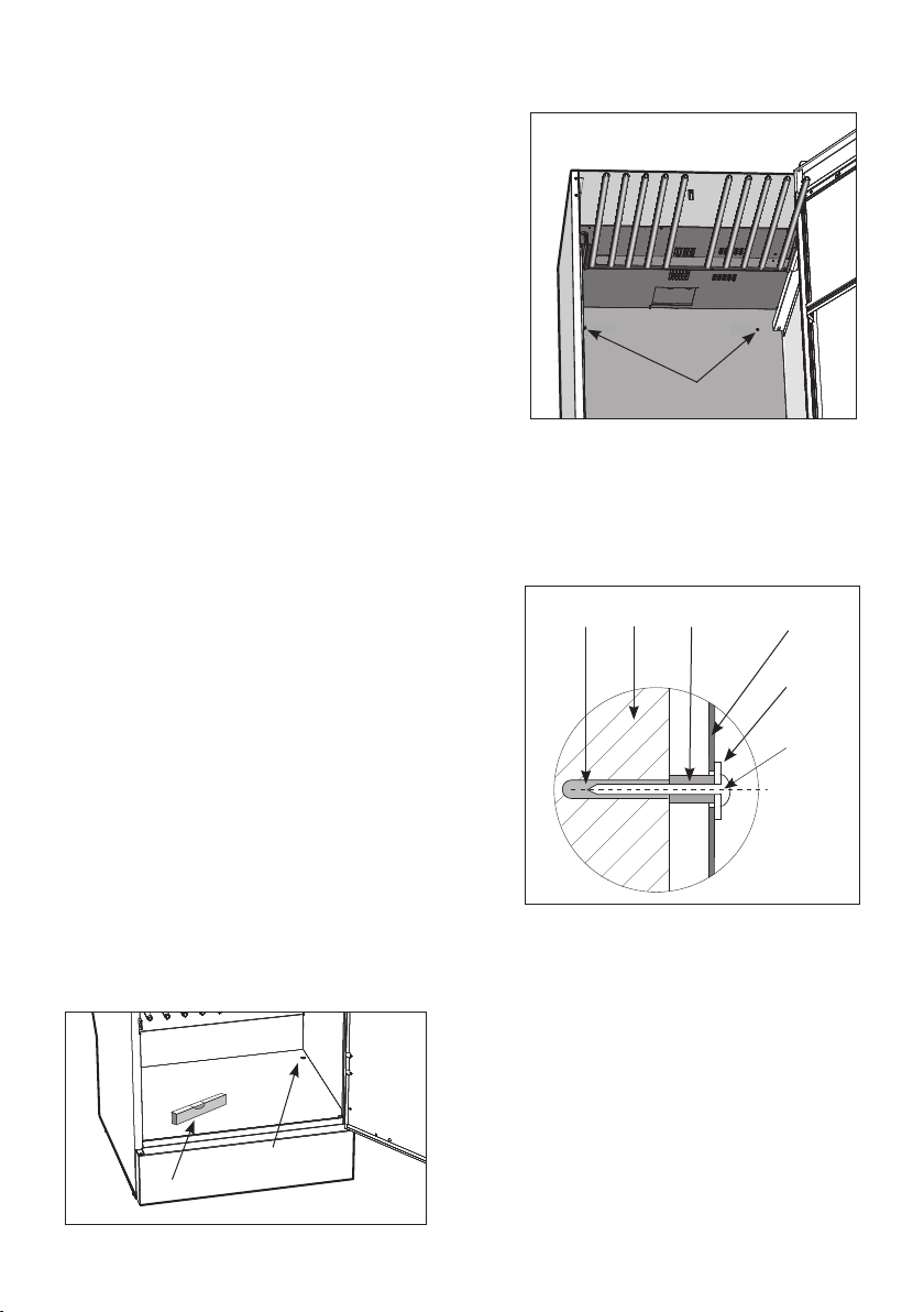
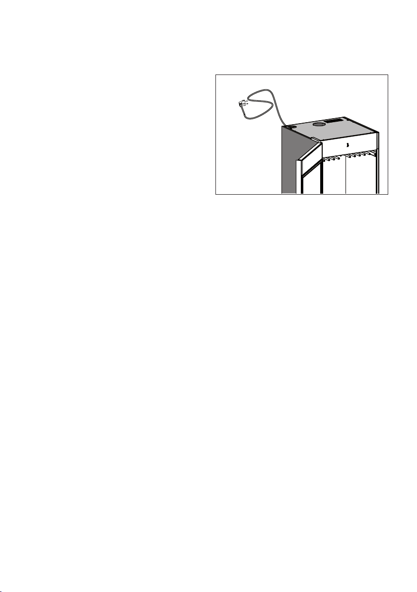
Check that all transport safety devices have been
removed before connecting the drying cabinet.
_______________________________________
Keep packaging materials such as plastics and
polystyrene foam away from children
______________________________________
________________________________________
Take care, as the drying cabinet is
top-heavy and can easily tip over.
Do not move the cabinet alone,
make sure you are at least two.
________________________________________
Complete delivery should include:
Cabinet with pre-installed fan unit
Installation kit
User manual
_______________________________________
Check that the goods have not been damaged
in transport. Any transport damage must be
reported to the retailer within 7 days
______________________________________
UNPACKING
Remove all packaging material; do not use sharp tools that could damage the product.
_______________________________________
After unpacking the product, check that it is free
from damage. Any damage, faults or missing parts
must be reported to the retailer immediately
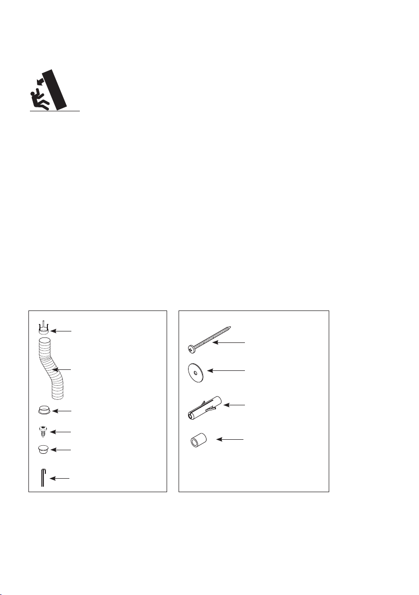
_______________________________________
Installation kit,
- for cabinet - for wall fixing
Draft stabilizer (1)
Hose (1)
Spigot (1)
Fixing screw for spigot (2)
Cover plug, white (4) for
adjustable feet
Allen key (1)
Screw TRX 5x70 zinc-
plated (2)
Washer NB 5x25 (2)
Wall plug (2)
Spacer 8.2x12x15 (2)
REVERSING THE DOOR
The cabinet is supplied from the factory with a right-hung or left-hung door. The door can be reversed
afterwards.
If this is required, contact Award Appliances.

3
25
4
7
1
6
7
1. Pre-drilled holes
2. Wall plug
3. Wall behind the cabinet
4. Spacer
5. Drying cabinet back wall
6. Washer
7. Attachment screw
8. Spirit level
9. Cover plug (4)
PLACEMENT
_________________________________________
The drying cabinet is only intended for use indoors
in a dry area.
_________________________________________
Do not place the drying cabinet in an area where
high-pressure water is used for cleaning.
______________________________________
LEVELLING
The drying cabinet must be installed upright on a at
surface and be supported by all four feet. It can be
levelled using the adjustable feet.
Use the supplied Allen key to adjust the feet from
inside the cabinet.
Press the four covering plugs rmly into the holes.
SECURING TO WALL
The cabinet must be secured to the wall to prevent it
from tipping over.
1Place the cabinet in the desired location, open the
door and slide out the upper set of hangers.
2Drill two 8 mm holes in the wall through the pre-
drilled holes (1) in the rear of the cabinet.
3Insert the wall plugs (2) into the wall. Slide a spa-
cer (4) on to each screw (7) and t them with the
washers as shown. The screws are found in the
installation kit.
_________________________________________
WARNING! The drying cabinet must not be used
unless it has been secured to the wall,
as it could tip forwards otherwise.
_________________________________________
8
9 (4)

8
CONNECTING TO VENTILATION
VENTILATION/AIR SUPPLY
When the cabinet is running it produces 45 m³ of damp air per hour. You should therefore ensure
that the room is well ventilated to replace the damp air that is extracted.
The drying cabinet should be connected to a ventilation system that meets the relevant standards.
The drying cabinet can be connected to a ventilation duct in two ways, either by using the draft sta-
bilizer or by connecting directly to a mechanical extractor.
If the drying cabinet is connected to an existing ventilation system the draft stabilizer must always be
used, to prevent interference with the general ventilation in the premises.
Direct connection should only be used when a dedicated extractor duct is provided for the drying cabinet.
The manufacturer recommends that the drying cabinet is connected using the draft stabilizer.
Place the supplied spigot over the hole in
the top of the cabinet, insert the screws and
secure the spigot.

3
2
1
1
2
3
9
DIRECT CONNECTION TO MECHANICAL EXTRACTOR
________________________________
The insert is not supplied.
________________________________
Make sure the cabinet air intake is not
blocked.
________________________________
______________________________
Make sure the air intake is not blocked
______________________________
Do not connect the drying cabinet to
an existing chimney.
______________________________
1. Humid air out
2. Ventilation from the room
3. Flexible hose
4. Spigot
5. Draft stabilizer
6. Air intake
WITH DRAFT STABILIZER
Connect the exible hose to the spigot. Connect the other end of the hose to the draft stabilizer and
then secure this over the exhaust vent in the room.
1. Draft stabilizer
2. Flexible hose
3. Spigot
1. Insert
2. Flexible hose
3. Spigot
Air intake
Humid air out
Air intake
Humid air out
When the cabinet is connected directly
to a ventilation duct the whole room is
ventilated through the drying cabinet.
Connect the exible hose to the insert
and to the spigot.

3.dxf
10
The drying cabinet must be connected to a 230 V,
single-phase supply at 50 - 60 Hz, via an earthed
wall socket.
Fuse 10 A.
The drying cabinet is supplied ready for connection
with a power cord and earthed plug.
ELECTRICAL SUPPLY
_______________________________________
The drying cabinet must be connected to an
earthed wall socket using the power cord supplied.
_______________________________________
The socket must be positioned so that the appli-
ance can be easily unplugged if necessary.
_______________________________________
Check that the electrical supply matches the data
on the rating plate and that the supply is earthed
correctly according to the relevant standard. We
recommend that the supply is tted with a residual
current device.
_______________________________________
The socket must have its own fused circuit.
_______________________________________
Do not connect the drying cabinet to the power
supply with an extension lead as the necessary
safety cannot be guaranteed (risk of overhea-
ting).
_______________________________________
The manufacturer will not accept any responsi-
bility if electrical connections are not made as
described in this user manual.
_______________________________________
If the power cord for any reason is damaged, it
must be replaced. A genuine part can obtained
from the cabinet dealer. A replacement cord may
only be installed by a qualied electrician/service
agent.
_______________________________________

11
BEFORE USING THE DRYING CABINET
______________________________________
Read this user manual before starting
to use the drying cabinet
______________________________________
_______________________________________
CAUTION! Read the safety instructions on page 3
before using the cabinet.
_______________________________________
1 Check that the cabinet is securely attached
to the wall. See page 7.
2Check that all packaging material has been
removed.
3Wash the inside and outside of the drying ca-
binet using warm water and a mild detergent.
Then dry it carefully. See also the section on
‘Care’later on in the manual.
There are three sets of hangers inside the cabinet.
Each set has a number of rails for hanging items
to dry, as described below. The most ecient
drying results are obtained by hanging the items
in this way.
Hang the items to suit the amount of space
they take up – not how much they weigh.
For best eciency – do not lay items at
across the hangers.
Hang long items closest to the walls of the
cabinet and shorter items near the middle.
Raise the two lower sets of hangers if you
need to dry long items.
Hang gloves, hats, scarves and the like on the
hangers on the inside of the door.
Do not overload the drying cabinet. This
causes laundry to crease and leads to uneven
drying. If possible leave space between items.
If there is a risk of discolouration from some
items, leave plenty of space around them.
Avoid drying heavy garments together with
lighter items as they take much longer to dry.
Lay knitted garments at to dry. If these are
hung they will stretch excessively due to their
weight when wet.
USER ADVICE
Always follow the advice on the care label, if
provided.
If softener or antistatic agents are used, fol-
low the manufacturer’s instructions for these
products.
AIR FLOW
The diagram shows the air flow through the
drying cabinet.
___________________
NOTE! When the ca-
binet is cold the door
seal may not close com-
pletely. But once the
cabinet is warm the seal
will expand and provide
a complete seal.
___________________
_______________________________________
NOTE! Do not block the air ow through the
middle of the cabinet (large arrows in diagram
above) as this will considerably reduce the drying
performance.
_______________________________________
ARRANGING ITEMS FOR DRYING

12
PROGRAMME
DRYING PROGRAMME
The cabinet has four drying programmes:
High automatic or high manual programmes,
Low automatic or low manual programmes.
The high and low automatic programmes switch
the cabinet o automatically when the laundry
is dry.
For the manual programmes you select the dry-
ing time yourself, between 1 and 3 hours.
PROGRAMME SELECTION
High automatic:
For normal laundry.
High manual:
For thick fabrics, such as lined overalls.
Low automatic:
For laundry that requires gentle drying.
Low manual:
For thick fabrics that require gentle drying, such as
lined overalls with a delicate outer layer.
Button for selecting High drying programme
Button for selecting Low drying programme
Stop button
Programme selection LEDs
CONTROL PANEL
The cabinet has two programme buttons for se-
lecting the drying programme and a stop button
to end the selected drying programme.
To the left of each programme button is an LED.
The operation of the LEDs is shown below.
The drying programme is divided into two phases:
Drying process: LED – steady glow
Cool-down phase: LED – ashing

13
CHILD LOCK
To prevent accidental operation the drying cabinet has a
child lock feature.
SWITCHING CHILD LOCK ON/OFF
Hold in the Stop button and press the Low button at the
same time. Both programme selection buttons will ash to
show that the child lock has been switched on or o.
The child lock is switched o by default.

14
DRYING WITHOUT CHILD LOCK
AUTOMATIC PROGRAMME
pThe drying phase starts immediately when you press the desired programme button.
The LED for the selected programme glows steadily.
_________________________________________________________________________________
Press the programme selection button once rmly; do not hold it in.
_________________________________________________________________________________
The drying process ends automatically when the items are dry, and the programme then switches
to the cool-down phase. The LED ashes during the cool-down phase.
_________________________________________________________________________________
If you happen to hold the button in for 5 seconds or more, the programme selection LED will ash instead,
indicating that you have selected the manual drying programme. Release the button, press the STOP
button and start again.
_________________________________________________________________________________
You can always cancel the current setting by pressing the STOP button
_________________________________________________________________________________
MANUAL PROGRAMME
pPress and hold the desired programme selection button.
pRelease the button when the LED starts ashing.
_________________________________________________________________________________
You can now set the programme drying time. The LED will continue to ash for 10 seconds, after which
the cabinet will be switched o if you have not set the drying time.
_________________________________________________________________________________
pTo set the drying time, press the same button again:
once to set the timer for 1 hour,
twice to set the timer for 2 hours or
three or more times to set the timer for 3 hours.
_________________________________________________
The maximum drying time is 3 hours.
_________________________________________________
After 10 seconds the LED will stop ashing and will glow steadily.
The drying programme switches to the cooldown phase when the set time has elapsed. The LED
ashes during the cool-down phase.
________________________________________________________
You can always cancel the current setting by pressing the STOP button.
________________________________________________________

15
PAUSING A PROGRAMME
If the door is opened during the drying phase the heater is turned o and the fan continues to run for
a further 5 minutes. The LED for the paused programme will ash during this 5-minute period.
If the door is closed within this 5-minute period the drying programme will restart from the begin-
ning.
If the door is left open the drying phase is cancelled after 5 minutes and must be restarted manually.
STOPPING THE DRYING PHASE
pPress the Stop button to end the drying phase immediately

16
DRYING WITH CHILD LOCK
The child lock must rst be activated as described on page 16.
AUTOMATIC PROGRAMME
pPress and hold the desired programme selection button.
pRelease the button when the fan starts.
The LED for the selected programme glows steadily.
_________________________________________________________________________________
If you happen to hold the button in for 10 seconds or more, the programme selection LED will ash
instead, indicating that you have selected the manual drying programme as described below. Release
the button, press the Stop button and start again.
_________________________________________________________________________________
The drying process ends automatically when the items are dry, and the programme then switches
to the cool-down phase. The LED ashes during the cool-down phase.
MANUAL PROGRAMME
pPress and hold the desired programme selection button.
pRelease the button when the LED start ashing.
_________________________________________________________________________________
You can now select the drying time for the programme. The LED will continue to ash for 10 seconds
after which the cabinet will be switched o if you have not set the drying time.
_________________________________________________________________________________
pTo set the drying time, press the same button again
- once to set the timer for 1 hour,
- twice to set the timer for 2 hours or
- three or more times to set the timer for 3 hours.
__________________________________________________
The maximum drying time is 3 hours
__________________________________________________
After 10 seconds the LED will stop ashing and will glow steadily.
The drying programme switches to the cooldown phase when the set time has elapsed.The LED
ashes during the cool-down phase

17
PAUSING A PROGRAMME
If the door is opened within the drying phase the heater is turned o and the fan continues to run for
a further 5 minutes. The LED for the paused programme will ash during this 5-minute period.
If you shut the door during this 5-minute period the drying programme will restart from the begin-
ning.
If the door is left open the drying phase is cancelled after 5 minutes and must be restarted manually.
STOPPING THE DRYING PHASE
pHold in the Stop button for at least 5 seconds.The current programme selection LED will ash
to show that the child lock is activated. After 5 seconds the drying phase will be cancelled
and the LED will go out.
_________________________________________________________________________________
If the Stop button is held in for less than 5 seconds the LED will continue to glow steadily or ash (de-
pending on whether the button is pressed during the drying or cool-down phase). The programme will
then continue.
_________________________________________________________________________________

18
THERMAL CUT-OUT
The cabinet is tted with a thermal cut-out that is reset auto-
matically when the temperature inside the cabinet has fallen to
an acceptable level. The reset delay varies between 10 and 15
minutes from the time when the thermal cut-out was tripped.
The cabinet cannot be restarted while the thermal cut-out
is tripped.
If this happens, always wait for 15 minutes and then try to
restart the cabinet before reporting a fault.
If there are repeated cut-outs, contact your supplier.

TS 560-E
19
CARE
CLEANING
_______________________________________
NOTE! Do not wash with a high-pressure washer!
_______________________________________
SERVICING
Before contacting the service department, make a
note of the model name, article number and serial
number of the drying cabinet.
This information can be found on the rating plate
inside the cabinet.
Rating plate (inside)
The exterior of the cabinet can be cleaned
with a damp cloth and mild detergent.
Dust tends to collect around the air intake,
beneath the cabinet and on top of the cabi-
net.
This can interfere with operation and cause
the dryer to stop working. To avoid such
problems you should vacuum- clean the air
intake and top of the cabinet at least once a
year, or more often depending on the area
the cabinet is installed in.
REPLACEMENT PARTS
If the power cord is damaged for any reason it must
be replaced. Genuine spare parts can be obtained
from the retailer.
_______________________________________
NOTE! A replacement power cord should only be
tted by a qualied electrician!
_______________________________________

20
TECHNICAL DATA
Capacity: 4 kg of dry laundry
Evaporation rate: 17 g/min
Electrical supply: Single phase 230V, 50-60 Hz
Motor: 35 W
Heating element: 1500 W
Thermal cut-out: Yes
Fan capacity: 180 m³/hour
Total hanger length: 16 metres
Dimensions: Height 1715 mm
Width 600 mm
Depth 625 mm
Weight: ~54 kg
Colour: White
Sound level: approx.48 dB(A)
ENERGY CONSUMPTION AND DRYING TIMES
Drying times for laundry after spin-drying *)
Setting Energy consumption
Drying time
Temperature
High ca. 0.4 kWh/kg of laundry
approx 140 min
approx. 45 °C
Low ca. 0.6 kWh/kg of laundry
approx. 120 min approx. 60 °C
____________________________________________________________
*) Specied values apply to drying cabinet connected by ventilation adapter.
Values may vary depending on spin speed
____________________________________________________________
Table of contents
Other Award Dryer manuals
Popular Dryer manuals by other brands

Samsung
Samsung DV456 Series technical information

Electrolux Professional
Electrolux Professional TD6-20LAC user manual

Alliance Laundry Systems
Alliance Laundry Systems D0582 installation instructions

Frigidaire
Frigidaire GLGQ2170KE0 installation instructions

Whirlpool
Whirlpool W10184585B installation instructions

AEC
AEC AD Series Operation and installation manual