AWELL LWRE2012 User manual
PLEASE READ THESE INSTRUCTIONS CAREFULLY BEFORE INSTALLATION.
PLEASE RETAIN INSTRUCTIONS FOR FUTURE REFERENCE.
LWRE2012
Universal LED Exit Light
Important:
It is illegal for anyone, except for a licensed electrician to install or maintain this product. Before installaon,
ensure that the electricity supply has been switched off and isolated. Installaon must be carried out in
accordance with the relevant Australian and Internaonal Standards.
Specificaon:
Operang Supply : 220-240V / 50-60Hz
Operang Mode : Maintained and Non-maintanined Switchable
Operang System : Self-Tesng
Baery : LiFePo4
Compliance : AS 2293
Viewing : 24m
Mounng : Ceiling /Wall Mount, Suspended from Ceiling
Installaon:
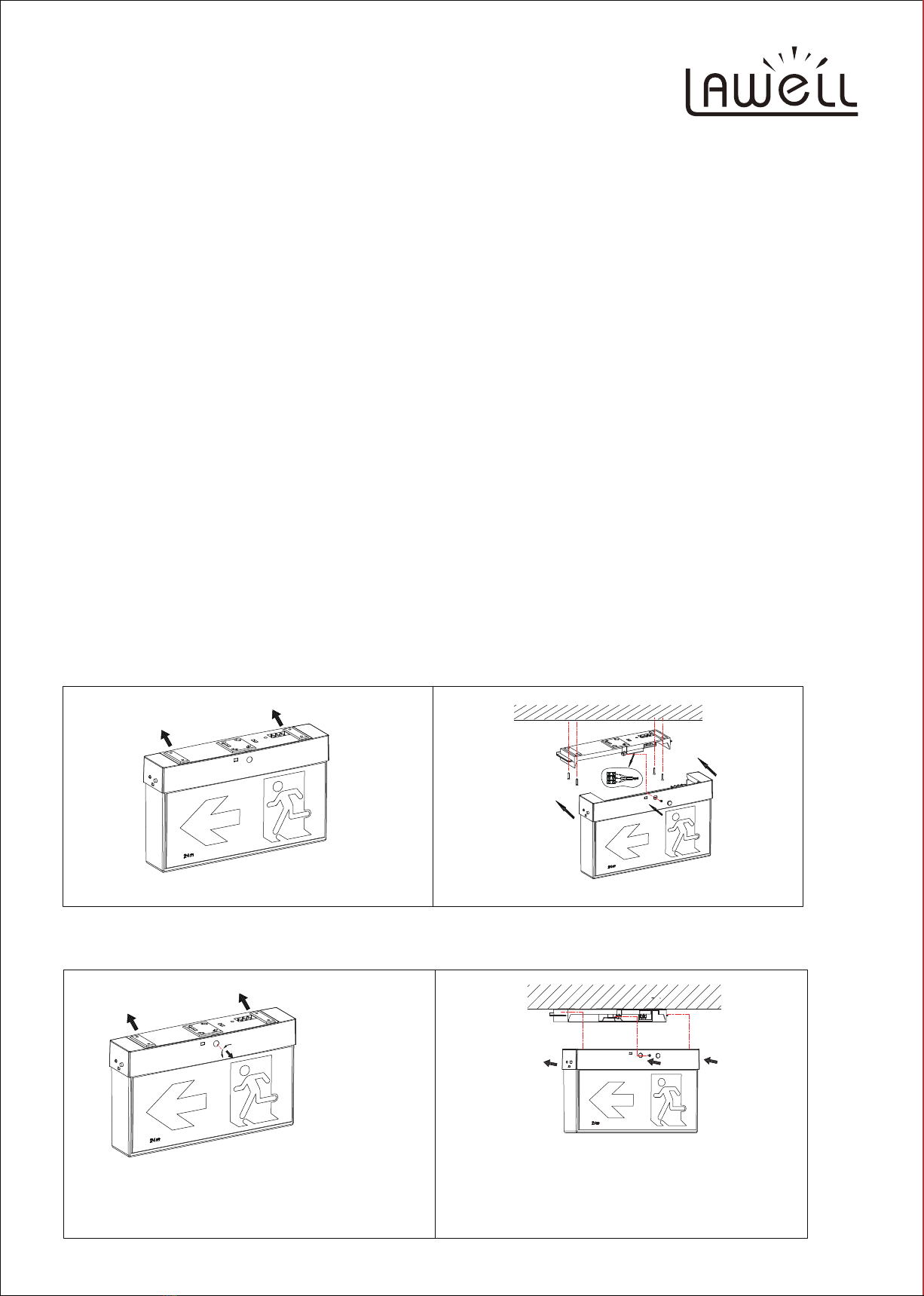
1. New Install with LWRE2012
Remove the cover using a flat blade screwdriver, release the clip by pushing in and down.
The top cover can then be removed by sliding it away from the screwdriver.
The cover must be mounted prior to aaching to the body (see Fig.2).
Mount cover and connect wiring to termials.
Assemble the product by sliding the body into place.
Fig.1 Fig.2
Use a tool to take off the Round locking tab from the base;
Remove the plate by sliding it away;
Asemble the body to the base, then push the round locking tabs
back in with supplied screw, to complete the process.
Fig.1 Fig.2
2. Replacement with exisng Clevertronic Base

Emergency Swap Funcon:
When permanent power off, the light switch to baery power supply.
Press and hold the Test buon for 1 seconds, the light exit emergency mode and goes to stanby mode.
Maintain and Non-maintain switchable: There is a SW2 switch on the internal PCB board.
Self-Tesng Funcon:
1. LED indicator light funcons:
Different lights under different system status (Only use one Red/Green LED, Yellow is shown when red and
green are both on.)
3. Replacement with exisng EKtor Base
Use a tool to take off the Round locking tab and Square locking
tab from the base
Terminal A: Fit Clevertronic and LWRE2012 Base
Terminal B: Fit Ektor Base
Fig.1
Fig.2
Terminal A
Terminal B
Unscrew the terminal A (keep the screw) (see Fig.2 and Fig.3);
unscrew the “L” wire and “N” wire from the terminal A and connect with terminal B;
then screw the terminal B to posion “E” (see Fig.2 and Fig.4)
L
N
Fig.3
Fig.4
C
L
N
Engage the exit body to the base, and push the round and squre locking
tabs back in, to complete the process.
Fig.5
install the terminal to posion “E”

1 Normal constant 240V Green is on when fully charged
2 Normal constant 240v Red is on when NOT fully charged
3 Waing for self-tesng Red is flashing slowly in 1Hz. (1 second)
4 Self-tesng is going on Green is flashing slowly in 1Hz. (1 second)
5 Quick start Self-tesng Green is flashing fast in 4Hz. (0.25 second)
6 Self-tesng Pass (90min) Red and Green flash slowly one aer the other in 0.5 Hz
(Each is on for 2 seconds)
7 Self-tesng Fail Yellow is always on
8 Baery Fault Yellow is flashing slowly in 1Hz
9 Light Source Fault Yellow is flashing quickly in 4Hz
2. Imitaon of Power-off status:
Press test buon to trigger off emergency mode.
Baery kicks in and start supplies power to the light. Release test buon and return to normal.
3. Manual Self-tesng funcons:
Press test buon 5 mes (Each within 4 seconds), the light goes into Self-tesng mode.
When the baery is Not fully charged, the Red indicator light flashes slowly.
When the baery is fully charged, the Green light flashes slowly and goes to baery discharge and emergency
mode.
Self-tesng goes on unl the baery is fully discharged, it then goes back to normal.
If the discharge period is less than 90 minutes, the Yellow indicator light is always on.
If the discharge period is more than 90 minutes, the Red and Green flash slowly one aer the other.
The Self-tesng result keeps showing for 5 days. Press test buon once and quickly to clear the
self-tesng result and goes back to normal.
If no one clears the result aer 5 days, it goes back to normal by itself.
Press the test buon again, it will show the last test result for 1mins.
Press the test buon for 2 seconds during the self-tesng period anyme to exit self-tesng, and it won’t
show any results because self-tesng is not completed.
4. Syncronising and Re-seng test date funcon:
Turn off and on the main power 4 mes (Each within 4 seconds). The annual inspecon me for all the lights
on the same circuit will be reset and go into Self-tesng mode at same No.182 days automacally. The red
indicator or green indicator (depends on the charging status) will flash quickly for 5mins.
5. Automac Self-tesng funcons:
The light goes into Self-tesng mode at No.182 days automacally. The light performs all the funcon and
displays as described in Point 3. When everything goes normal without any faults, it automacally goes back
to normal 240v status aer baery over-discharge protecon kicks-in.
6. Group Manual Self-tesng funcon:
Turn off and on the main power 6 mes (Each within 4 seconds). All the lights on the same circuit start
Self-tesng. It is the same methods and philosophies as point 3.
7. Special notes:
a). Under the automac self-tesng mode, the light will restart counng 182 days aer the baery is
fully discharged and goes back to normal 240v operaon. Manual self-tesng and Group self-tesng
do NOT affect recounng 182 days when manually exit during the tesng.
b). All self-tesng funcons needs the baery to be fully charged. When the baery is not full, the red
flashes to wait for self-tesng.

1 Under Normal 240v Press and hold to enter into emergency mode, release to return
normal. Manually press the buon to clear the self-tesng results.
Manually press the buon 5 mes to trigger off Self-tesng.
2 Under emergency mode Press and hold for 1 seconds to exit emergency discharge. (Easy to
test in factory, no need to unplug and plug baery on the PCB board)
3 Under Self-tesng Press and hold for 1 seconds to exit emergency discharge.
8. Test Buon Fucon:
Note:
For first usage, power ON the unit for 24 hours to fully charge the baery. Interrupng the mains supply will
discharge the baery.
Warranty:
Products have 2 years (from date of purchase) replacement warranty including baery.
Products have to be connected to permanent live power otherwise warranty will be void.
Must be installed by licensed electrician.
This warranty does not cover loss or damage by misuse, incorrect installaon, incorrect voltage or
non-authorized electrical connecons, adverse external condions (such as power surges and dips, exposure to
heat, corrosion etc).
Products that have been altered in any way or used other than in accordance with instrucon are not covered by
this warranty.
Table of contents
Popular Light Fixture manuals by other brands


Chauvet Professional
Chauvet Professional ROGUE R1 BEAM WASH user manual

Martin
Martin MAC 250 Krypton user manual

Cooper Lighting
Cooper Lighting Halo L3232E Specification sheet

Stageline
Stageline ODW-2410RGBW instruction manual

Lightolier
Lightolier Paralyte 2424 PLA2G9LS26U specification

Lightolier
Lightolier Lytespan 83ED17S specification