Awenta PRO AUROS 505 Specification sheet

________________________________________________________________
AWENTA Spółka Jawna, Warszawska 99, 05-300 Stojadła
AWP.VER.01.2024_EN
Operation and Installation Manual
Air handling unit with heat recovery
AUROS 305 / 405 / 505 / 605
Air handling unit equipped with Aero 4A ver.2 ventilation controller with NANO COLOR 2 ver.1 control panel
Applies to models: VER305L/02 VER305P/02 VER305LCF/02 VER305PCF/02
VER405L/02 VER405P/02 VER405LCF/02 VER405PCF/02
VER505L/02 VER505P/02 VER505LCF/02 VER505PCF/02
VER605L/02 VER605P/02 VER605LCF/02 VER605PCF/02

2

3
TABLE OF CONTENTS
1. OPERATOR’S MANUAL
1.1. IMPORTANT INFORMATION/SAFETY INSTRUCTIONS................................................................................................... 4
1.2. INTENDED USE ............................................................................................................................................................. 5
1.3. TRANSPORT AND STORAGE ......................................................................................................................................... 5
1.4. SAFETY MEASURES REGARDING OPERATING OF THE UNIT ......................................................................................... 5
1.5. TECHNICAL SPECIFICATION .......................................................................................................................................... 6
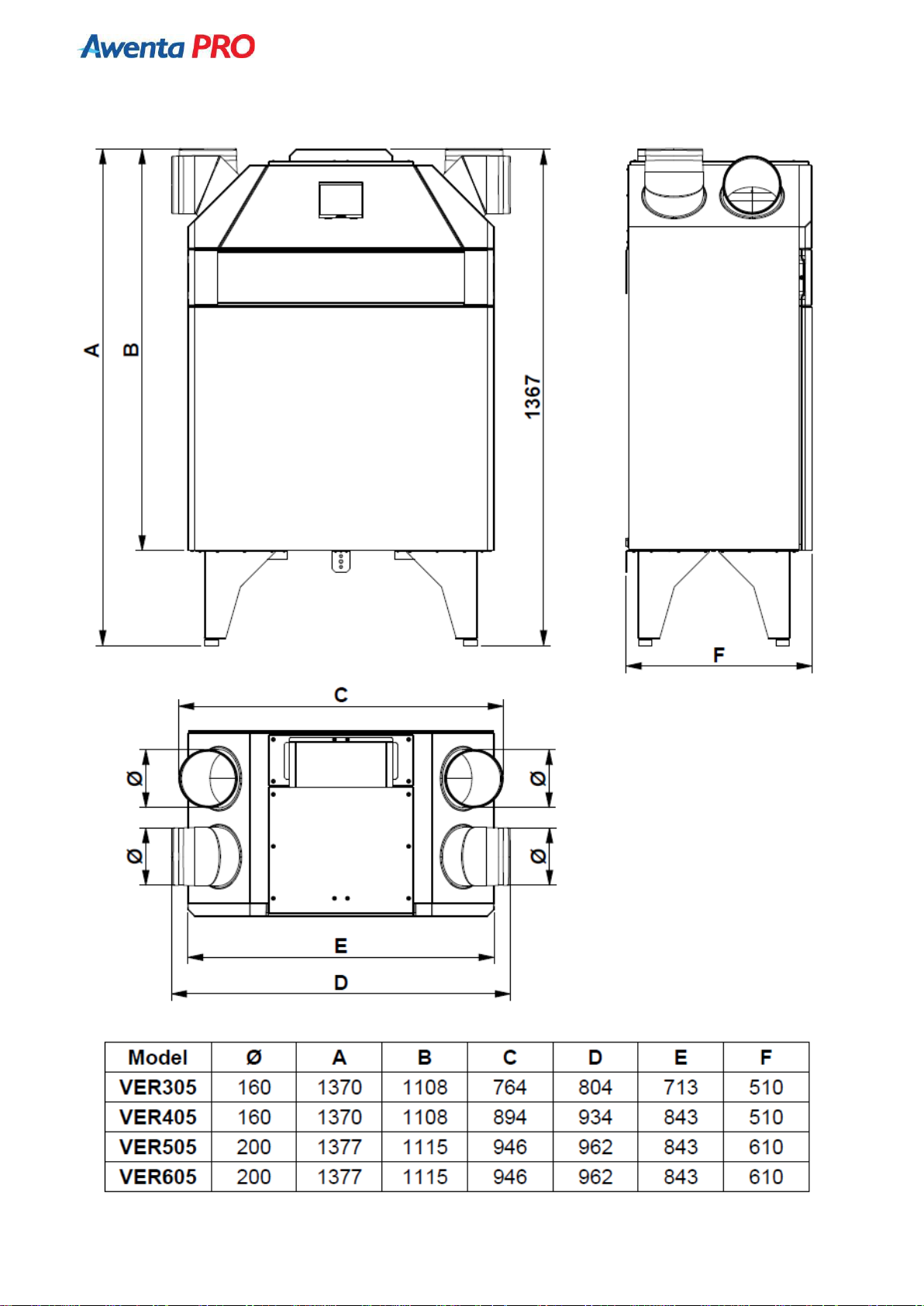
1.6. TECHNICAL DRAWINGS ................................................................................................................................................ 7
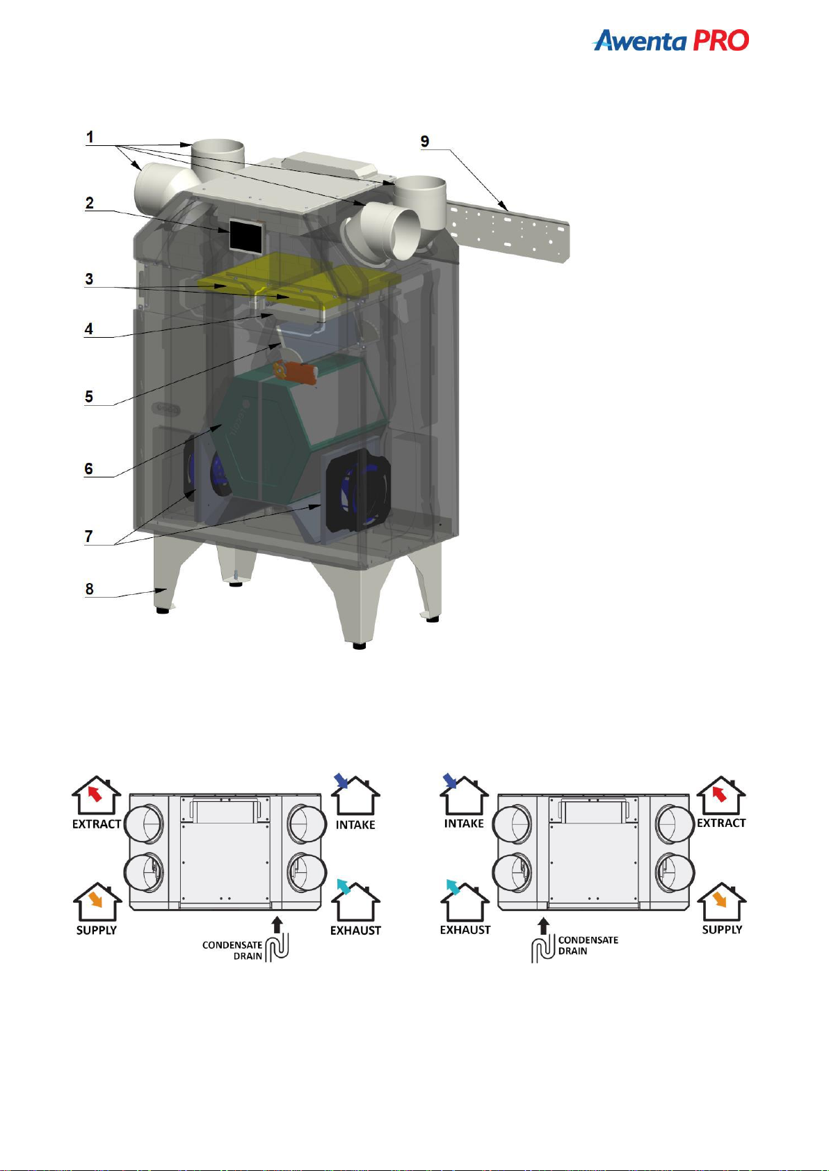
1.7. BASIC COMPONENTS OF THE UNIT.............................................................................................................................. 9
1.8. LAYOUT OF CONNECTIONS .......................................................................................................................................... 9
1.9. OPERATION PRINCIPLE............................................................................................................................................... 10
1.10. ITEMS OF EQUIPMENT............................................................................................................................................. 10
1.11. INSTALLING AND PREPARING THE UNIT FOR OPERATION ....................................................................................... 10
1.12. MAINTENANCE......................................................................................................................................................... 13
1.13. PRE-HEATER ............................................................................................................................................................. 15
1.14. WASTE MANAGEMENT NOTICE ............................................................................................................................... 15
2. NANO COLOR CONTROL PANEL
2.1. OPERATION PRINCIPLE............................................................................................................................................... 16
2.2. INSTALLATION ............................................................................................................................................................ 16
2.3. DESCRIPTION OF THE MAIN SCREEN ......................................................................................................................... 18
2.4. OPERATION MODE ..................................................................................................................................................... 20
2.5. SETTINGS.................................................................................................................................................................... 21
2.6. TEMPERATURE SETTINGS........................................................................................................................................... 21
2.7. THERMOSTAT INFO .................................................................................................................................................... 22
2.8. VENTILATION INFORMATION SCREEN........................................................................................................................ 22
2.9. FIREPLACE MODE ....................................................................................................................................................... 23
2.10. CHANGING THE SYSTEM OPERATION MODE ........................................................................................................... 23
2.11. SENSORS .................................................................................................................................................................. 24
2.12. VEX4 MODULE ......................................................................................................................................................... 26
2.13. SMART MODE .......................................................................................................................................................... 27
2.14. FOULED FILTER INDICATION..................................................................................................................................... 28
2.15. MAIN MENU............................................................................................................................................................. 28
2.16. SCHEDULE SETTINGS................................................................................................................................................ 29
2.17. SERVICE MENU......................................................................................................................................................... 29
2.17.1. IN-OUT .................................................................................................................................................................. 30
2.17.2. DISTRIBUTOR ........................................................................................................................................................ 30
2.17.3. NANO .................................................................................................................................................................... 31
2.17.4. VENTILATION......................................................................................................................................................... 32
2.17.5. SENSORS ............................................................................................................................................................... 34
3. NANO WIRELESS NETWORK ...................................................................................................................................36
4. MODBUS RTU PROTOCOL CONFIGURATION...........................................................................................................36
5. VLAN INEXT INTERNET MODULE ...........................................................................................................................36
6. WIRING DIAGRAMS
6.1. ELECTRICAL DIAGRAM OF THE AERO 4 CONTROLLER –version for operation diagram 1. Standard......................... 37
6.2. CONNECTING THE NANO COLOR CONTROL PANEL ................................................................................................... 38
6.3. CONNECTING THE NANO COLOR CONTROL PANEL WITH C14 - VRS NETWORK CONVERTERS ................................. 38
6.4. CONNECTING THE NANO COLOR CONTROL PANEL WITH THE iNEXT VLAN INTERNET MODULE .............................. 39
6.5. CONNECTING THE NANO COLOR CONTROL PANEL WITH VACS-1 or VSPM AIR QUALITY SENSOR............................ 38
6.6. CONNECTING THE NANO COLOR CONTROL PANEL WITH THE VSHC or VSHW SENSOR………………………………………… 39
6.7. CONNECTING THE NANO COLOR CONTROL PANEL WITH VSHC or VSHW and VACS-1 or VSPM SENSORS ............... 39
6.8. CONNECTING THE VGER405/605 PREHEATER ........................................................................................................... 40
7. ATTACHMENTS
7.1. PRODUCT DATA SHEETS/ENERGY LABELS .................................................................................................................. 41

________________________________________________________________
AUROS 305 / 405 / 505 / 605 Instruction Manual
4
1. OPERATOR’S MANUAL
1. 1. IMPORTANT INFORMATION
Read the Operator’s Manual carefully before installation or any other activity related to work with the unit! AWENTA
takes not responsibility for any damage resulting from incorrect operation, non-intended use or unauthorised repairs or
modifications of the product.
This installation manual is an essential part of the product and contains important technical information and instructions
regarding the occupational safety. Carefully read the operation and installation manual and keep it available in a readily
accessible place for future reference. The manual is also available at www.awentapro.pl
Safety precautions:
● This product can be used by children at least 8 years old, by people with impaired
physical and/or mental abilities, and by people without any experience in or
understanding of the operation of the product, if supervised or instructed by a
competent adult in the safe use of the product so that they understand the
relevant operating risks. This product is not a toy and children should not play with
it. Children should not be allowed to clean or maintain the product without
supervision of an adult.
● The unit is intended for indoor electrical installation provided with means or
devices having contact breaks at all poles, ensuring complete isolation under
category III overvoltage conditions in accordance with the regulations for such
installation. The device should be connected directly to an earthed 230 VAC mains
socket.
● When installing and using the unit, it is mandatory to observe the provisions
specified in this manual and all the applicable local and national building, electrical
and technical standards.
● It is imperative to read all warnings in this manual and become familiar with the
warning signs located on the air handling unit, as they contain information for your
safety.
● Failure to follow the instructions and warnings contained in this manual may result
in personal injury and damage to the unit.
● If the unit is handed over/sold etc. to another user, this manual must also be
handed over.
● Assembly and repairs of the unit may only be carried out after it has been
effectively disconnected from the power network.
● It is forbidden to operate the unit beyond the temperature range specified in the
user manual, as well as in aggressive and potentially explosive environments.
● Do not place heating or other devices near the power supply cable of the unit.
● It is forbidden to connect the device to the mains if the power cord is found
damaged.
● If the inseparable power cord is damaged it should be replaced by the
manufacturer, a serviceman or by a qualified person in order to avoid hazards.
● The OHS rules must be observed, when using electrical equipment during the
assembly of the unit.
● Exercise care, when unpacking/unloading of the unit.
● Do not bend the power cord, avoid damaging it.
● Use the air handling unit only for its intended purpose. PE ЕС

________________________________________________________________
AUROS 305 / 405 / 505 / 605 Instruction Manual
5
1.2. INTENDED USE
The unit is equipped with a cross-flow plate heat exchanger, electric heater (sold separately) and is designed to save
thermal energy by its recuperation, being one of the elements used in energy-saving technology systems. The unit is
considered a supplementary device and must not be used as a stand-alone, independent heating source.
The unit is intended for securing continuous air exchange by means of forced ventilation in houses, offices, hotels, cafés
and other residential and public premises, as well as for recuperation of heat energy from discharged air to heat up
clean air coming from the outside. External air is heated by transferring heat energy from the exhaust air stream via a
heat exchanger. The unit is not intended for industrial use.
Air flowing through the unit must not contain volatile flammable or explosive substances, chemically active vapours,
dust with large particles, soot, fats or media conducive to the formation of harmful substances (toxic substances, dust,
pathogenic microorganisms), sticky substances and fibrous materials.
The unit is designed for installation in a closed building, in the ambient air temperature from 0°C to +40°C, the relative
humidity of up to 90%.
WARNING! In the event of extremely unfavorable weather conditions (outside temperature below -10°C),
it is not recommended to use the air handling unit above 70% air flow. This may result in excessive cooling
of the room and incorrect operation of the device.
1.3. TRANSPORT AND STORAGE
Permissible storage and transport temperatures range from -20 to +50°C.
Transport and unpack the unit with care. Dispose of the packaging in an environmentally friendly manner.
1.4. SAFETY MEASURES REGARDING OPERATING OF THE UNIT
● Always and absolutely observe the safety regulations, warnings, comments, and cautions as recommended herein.
Failure to observe the safety regulations, warnings, and cautions and instructions in this document may result in
personal injury or damage.
● Do not touch the control panel or the electric feeder box with wet hands.
● It is forbidden to operate the unit with wet hands.
● The use of a high-pressure washer or water jet to clean the control panel is prohibited.
● Avoid any contact between the electric parts of the unit with water.
● It is not allowed to block the inlets and outlets of air conduits, when the unit is in operation.
● Maintenance of the unit may only be carried out, after it has been effectively disconnected from the power network.
● It is forbidden to place on the power supply cord any objects which could abrade, cut or damage it otherwise.
● It is forbidden to store explosive or flammable substances in the vicinity of the unit.
● It is forbidden to open the unit, when it is in operation.
● In case of unusual noise, odour and smoke, immediately turn the control panel off and contact the service centre or
the manufacturer.
● The installation of the unit should always be carried out in compliance with the general and local construction, safety
and installation regulations issued by the relevant official institutions and the energy and water supply companies.
● The unit should be connected to the ventilation system before commissioning. Ventilation ducts provide protection
from access to rotating fan blades. The ducts shall be secured against slipping off its connections in a manner requiring
the use of tools.

________________________________________________________________
AUROS 305 / 405 / 505 / 605 Instruction Manual
6
1.5. TECHNICAL SPECIFICATION
Specifications:
AUROS 305
AUROS 405
AUROS 505
AUROS 605
Supply voltage
230 VAC/50Hz
Maximum power consumption
(without the pre-heater)
195 W
280 W
295 W
340 W
Pre-heater power output
2000 W
Electrical protection class
I
IP protection class
IP33
Capacity (at 100 Pa)
313 m3/h
430 m3/h
508 m3/h
605 m3/h
Max motor speed
3600 rpm
4000 rpm
3500 rpm
4400 rpm
Noise level
(Acoustic pressure - 3m)
44.0 dB(A)
44.3 dB(A)
44.0 dB(A)
45.0 dB(A)
Type of heat exchanger
Cross-flow plate heat exchanger
Max. heat recovery efficiency
up to 95%
Heat exchanger material
Polystyrene
Housing material
EPP + powder coated steel
Filter –intake vent
VM5ER405 - M5 ISO ePM10
(optional VF7ER405 - F7 ISO ePM1)
VM5ER605 - M5 ISO ePM10
(optional VF7ER605 - F7 ISO ePM1)
Filter –exhaust
VM5ER405 - M5 ISO ePM10
VM5ER605 - M5 ISO ePM10
Pre-filter intake/exhaust
VFWER405 (optional)
VFWER605 (optional)
Connection pipes
Rotatable (vertical/horizontal)
Diameter of air connector
160 mm
200 mm
Diameter of condensate drain
connector
32 mm
Mounting position
Vertical (wall-mounted or standing)
Weight
43 kg
46 kg
52 kg
Controller type
AERO 4 + NANO COLOR 2
Dimensions
[height x width x depth]
1368 mm x 764
mm x 510 mm
1368 mm x 894
mm x 510 mm
1375 mm x 946 mm x 610 mm
By-pass
Automatic (100% by-pass)
Fans
2x radial fan with EC motor
Constant Flow system
YES
(VER305LCF,
VER305PCF
versions)
YES
(VER405LCF,
VER405PCF
versions)
YES
(VER605LCF,
VER605PCF
versions)
YES
(VER605LCF,
VER605PCF
versions)
Modbus RTU communication
YES
YES
YES
YES
Internet module
VLAN iNEXT (optional)
Air quality sensor
(CO2, PM2.5, PM10)
VACS-1 (optional)
Air quality sensor
(CO2, humidity, temp., PM1, PM2.5,
PM4, PM10)
VSPM (optional)
CO2concentration and humidity
sensor
VSHC (optional)
Humidity sensor
VSHW (optional)

________________________________________________________________
AUROS 305 / 405 / 505 / 605 Instruction Manual
7
1.6. TECHNICAL DRAWINGS
Wall-mounted version

________________________________________________________________
AUROS 305 / 405 / 505 / 605 Instruction Manual
8
Stand-alone version

________________________________________________________________
AUROS 305 / 405 / 505 / 605 Instruction Manual
9
1.7. STANDARD SYSTEM COMPONENTS
1.8. LAYOUT OF CONNECTIONS –LEFT / RIGHT VERSIONS
Left version Right version
(standard)
1.
Connection pipes
2.
Control panel
3.
Air filters
4.
Preheater*
5.
By-pass damper
6.
7.
Counter-flow heat exchanger
Fans
8.
Feet (optional)
9.
Wall bracket
*position of the heater for the LH version

________________________________________________________________
AUROS 305 / 405 / 505 / 605 Instruction Manual
10
Connection ports designation:
INTAKE –outdoor air intake duct
EXHAUST –used air exhaust duct
EXTRACT –duct removing used air from rooms
SUPPLY –duct supplying air to rooms
1.9. OPERATION PRINCIPLE
Fresh air is drawn in with the air intake located outside the building. Then, using ventilation ducts, the air is transported
to the air handling unit. After filtering, it flows to the heat exchanger where heat energy exchange from the exhaust
stream takes place. The air is heated in winter and cooled in the summer. Next, the supplied air flows to the so-called
“clean” areas such as a living room or bedroom.
Both, used and polluted air is extracted from the so-called “dirty” areas such as a toilet, bathroom, kitchen or laundry by
means of exhaust grilles or diffusers, and then directed to the air handling unit by means of exhaust ducts. After
filtering, it flows to the heat exchanger, where the heat or cold is “recovered” from the used air. The air is then moved to
an outlet located outside the building.
1.10. ITEMS OF EQUIPMENT
The standard accessories of the unit include the following:
● Cross-flow plate heat exchanger.
● M5 class supply and exhaust air filters.
● NANO COLOR control panel (as a standard, mounted in the front panel of the air handling unit, and can be moved to
any place in the room).
● Control panel cover.
● Wall bracket + securing angle bar.
● Flexible condensate drain pipe dia. 32 mm
1.11. INSTALLING AND PREPARING THE UNIT FOR OPERATION
Installation of the air handling unit
● The unit should be mounted in a vertical position with the connections facing upwards or sideways. The unit can be
fixed to the wall or placed on feet (optional).
● WALL MOUNTING
- The unit should be hanged at least 250 mm from the floor (distance required to provide space for the condensate drain
trap).
- Check whether the mounting structure can support the weight of the unit. Otherwise, the location intended for
installation must be reinforced with additional beams. The unit must be installed on a rigid and stable surface.
- The unit should be fixed to a vertical surface.
- The wall bracket should be fixed using dowels or other fasteners suitable for the type of material. After screwing on the
bracket, check its stability.

________________________________________________________________
AUROS 305 / 405 / 505 / 605 Instruction Manual
11
- After hanging the air handling unit on a wall bracket, the angle bar protecting it against accidental sliding off the wall
bracket must be attached.
● STANDING INSTALLATION
- For standing installation, feet appropriate to the model of appliance are required. Do not use other feet than those
provided by the manufacturer (feet sold separately).
- The feet are fixed with the Ø4.2 sheet metal screws included in the package.
- It is forbidden to use the control panel when not all the screws of the feet have been tightened.
- The unit should be installed on a level surface. If necessary, compensate for uneven floor surfaces with adjustable feet.
- The unit should stand firmly with all feet on the floor.
●The unit should be installed so as to enable its free opening for the replacement of filters, cleaning the exchanger and
other maintenance.
● Make sure the power supply system is suitable for the maximum power of the appliance. The permissible temperature
of the intake air is -20 to +50°C.
●The air handling unit should be installed in rooms where the temperature is above 0°C.
SECURING ANGLE BAR

________________________________________________________________
AUROS 305 / 405 / 505 / 605 Instruction Manual
12
Minimum lengths of ventilation ducts
To ensure the best efficiency of the air handling unit and to reduce aerodynamic losses due to turbulence, it is
recommended to install a straight section of air duct at the entry and exit of the unit.
The minimum recommended lengths of such straight sections:
- 25 cm of an air conduit at the inlet side;
- 60 cm at the outlet side.
In case of lack or short air ducts on one or several ports of the air handling unit it is necessary to protect the unit's
internal parts against entry of foreign objects, for example, install a protective grid or other device with mesh size not
larger than 12.5 mm, to prevent free access to the fans.
If the source of noise is where the spiral air duct is connected, replace the spiral air duct with a flexible duct to avoid
resonance. Flexible inserts can also be used to prevent resonating.
Draining of condensate
Connect the flexible condensate drain pipe to one of the ports of the drip tray, depending on the unit configuration
(LEFT/RIGHT). The dia. 32 mm pipe should be bent to form a trap (the height difference between the upper and lower
elbow of the trap should be at least 100 mm). The drain pipes have to be arranged with a slope of approximately 2%.
NOTE: Fill the drain system with water, before starting the unit for the first time! The drain
trap must be filled with water during operation at all times.
Make sure that water flows into the drain, otherwise condensate may accumulate inside the
unit when the recuperator operates, which in turn may damage the unit and cause water
leakage into the room.
The condensate drain system must be used in all rooms, in which air temperature is above
0°C! If the room temperature is below 0°C the condensate drainage system has to be
thermally protected and equipped with a heating device to prevent it from freezing.
ATTENTION! Condensate drainage is also recommended in air handling units with an
enthalpy exchanger, as in special cases a small amount of condensate may accumulate.
Connecting to the mains power supply
The unit must be connected to a 230V / 50Hz single-phase AC power supply network, using the original power cord
provided with the unit. Before connecting to the mains, check the cable for any mechanical damage caused by crushing,
cutting etc., which may result in an electric shock.
The unit must be connected to the power network, in compliance with the regulations and standards in force.
ATTENTION!
The control panel should be connected to a properly installed socket equipped with an earthing contact.
The power outlet should be located in an easily accessible place so that the plug can be pulled out easily
in case of danger. The panel ratings are given on the manufacturer's factory label. Any changes to the
internal connection are prohibited and will void the warranty.
Installation of air ducts
● The ventilation ducts should be secured against slipping from the connection stubs with cable ties.
● The distance between the air intake and the outlet should be at least 1.5 m.
● The air intake should be located on the shadiest building side as far as possible from sources of stale air (street,
chimney, etc.)
● Install the exhaust air duct with a slope to the unit.
● All ducts should be insulated to avoid inside condensation and excessive moisture accumulation.
● When installing the ducts, minimise the number of sharp bends, etc., to reduce resistance of the ducts.
● The ducting should be airtight. Use fittings with gaskets or seal the joints with e.g. adhesive aluminium tape.
● To reduce the transmission of vibrations and to make the unit run more quietly, connect it to the system with flexible
dampers on the intake and exhaust sides.
● The installation should follow a design prepared by an authorised designer.
● Make flow adjustments on the diffusers, based on measurements taken with an anemometer according to the air
balance obtained.
● Ceiling diffusers should be installed min. 30 cm from the walls.
● To ensure adequate flow between rooms:
- The gap under the internal door should have a minimum surface area of 7600 mm2
- At least 10 mm gap under a standard internal door with a width of 760 mm
- Do not cover the openings as this will disturb air circulation
min. 100 mm

________________________________________________________________
AUROS 305 / 405 / 505 / 605 Instruction Manual
13
● Recommended duct thickness depending on ambient temperature:
Air duct type:
Ventilation duct ambient temperature
from -20°C to 0°C
from 1°C to 14°C
from +15°C to 20°C
Insulation thickness for a given temperature range
Supply
20 mm + (200 mm)*
50 mm
20 mm
Exhaust:
20 mm + (200 mm)*
50 mm
20 mm
Intake
50 mm
50 mm
50 mm
Discharge
20 mm + (200 mm)*
20 mm
20 mm
*20 mm mineral wool insulation covered with aluminium foil on one side + a minimum of 200 mm of mineral wool as a
covering or casing for pipes laid in the attic without thermal insulation.
1.12. MAINTENANCE
ATTENTION!
It Is absolutely necessary to disconnect the control panel from power supply before performing any
maintenance operations.
ATTENTION!
Do not use corrosive chemicals and solvents during any maintenance work.
Filter replacement/cleaning
Fouled filters increase air flow resistance which reduces the amount of air supplied to the rooms, and increases power
consumption by the fans.
The filters should be cleaned as they become dirty, but at least 3-4 times per year. It is permitted to clean the filters with
a vacuum cleaner. After cleaning twice, the filters should be replaced with new ones.
Optionally the air handling unit can be equipped with a pre-filter to extend the life of the fine filters. The pre-filter
should be rinsed under running water and then dried before re-insertion, as it is reusable.
Filter change procedure:
●Remove the screws securing the filter flap (1);
●Remove the filter flap (2) mounted with magnetic holders;
●Remove the filter caps (3);
●Remove the pre-filters (4) –optional;
● Remove the M5/F7 filters (5);
● Install new or cleaned filters according to the above diagram in reverse order.
● Reset the filter fouling counter on the control panel
NOTE: Make sure if the arrow is pointing downwards when inserting the filters.

________________________________________________________________
AUROS 305 / 405 / 505 / 605 Instruction Manual
14
Fan maintenance (once a year)
Even with regular maintenance of the filters and
recuperator, dust deposits may accumulate in the fans,
which reduces the efficiency of the air handling unit
and the amount of air supplied to the rooms.
Use a soft cloth or brush to clean the fans. In order to
avoid possible damage to the rotor, do not use water,
chemically aggressive solvents, sharp objects etc.
Heat exchanger maintenance (once a year)
Even with regular filter maintenance, dust deposits can
form in the unit. In order to maintain high heat transfer
efficiency, the heat exchanger should be cleaned
regularly. Remove the heat exchanger from the air handling unit and wash it with warm water solution of neutral
detergent, then reinstall the dried heat exchanger.
Heat exchanger/fan cleaning procedure:
●Remove the filter flap (as per filter cleaning procedure);
●Remove the locking screws (1);
●Remove the front flap by pulling it upwards (2);
●Remove the press-fit plugs of the motor (3) or exchanger (4);
● Slide out the sealing inserts of the exchanger (5) –does not apply to the VER305 version;
● Remove the heat exchanger (6) completely and rinse with running water (reassemble after drying);
●Pull out the fan units (7) and then clean the fan blades with e.g. a soft cloth
(the power supply cable is long enough to allow free access to the motors –there is no need to disconnect the cables);
● After cleaning, assemble the unit according to the above diagram in a reverse order.
Maintenance of the condensate drain system (once a year)
The condensate drain system (drain pipe) may be contaminated by particles from the evacuated air. Check the function
of the drain pipe, by filling the drain tank with water and, if necessary, removing dirt from the drain trap and drain pipe.
Maintenance of air intake and exhaust ducts (twice a year)
Leaves and other impurities can clog ventilation grates and reduce both the efficiency of the unit and air flow. Check the
intake/exhaust grille twice a year and clean it, if necessary.
SEALING CARTRIDGE
*Does not apply to
the VER305 version

________________________________________________________________
AUROS 305 / 405 / 505 / 605 Instruction Manual
15
Maintenance of the air ducting (every 5 years)
Even if all the aforementioned maintenance activities of the air handling unit are performed properly, dust deposits may
build up inside the air ducts, which reduces the air handling unit's efficiency. Air ducts are maintained by periodic
cleaning or changing them.
1.13. PREHEATER
The device is equipped with a preheater, which can be used as one of the methods of protection against freezing of the
heat exchanger while the outside temperatures are below freezing. Other defrosting methods are the temporary
stopping of the supply fan or the opening of the By-pass damper.
Configuration of service settings for work with the preheater:
- defrosting temperature (default 5°C)
- defrosting method (set to HEATER)
- defrosting control range (default 1.5°C)
NOTE: A missing or damaged ejector sensor shuts down the heater.
1.14. WASTE MANAGEMENT NOTICE
. P
Do not dispose of waste electrical equipment with household waste.
The crossed-out wheelie bin symbol on this product that it is waste electrical an electronic
equipment (WEEE) at the end of its operating life and shall not be disposed with household waste.
The crossed-out wheelie bin symbol specifies that the product is subject to obligatory waste
segregation schedules for proper disposal. The product is made from recyclable materials and
components. The product user shall is required to return the product which has become WEEE to
a WEEE collection unit. The operators of WEEE collection units, including local WEEE locations,
product resellers and other WEEE collection locations managed by local authorities form a proper
waste disposal system. Proper WEEE disposal helps avoid harmful effects to humans and the
environment from the risk caused by hazardous components this product may contain. Your
household can make an important contribution to the recovery and recycling of WEEE. This
contribution fosters a behaviour which helps conserve the natural environment, which is a common asset for the
mankind. Households are among the leading consumers of small appliances and equipment. A rational management of
operation and disposal of small appliances and equipment will contribute to efficient recycling.

________________________________________________________________
AUROS 305 / 405 / 505 / 605 Instruction Manual
16
2. NANO COLOR CONTROL PANEL
2.1. OPERATION PRINCIPLE
The NANO COLOR determines the set room temperature and ventilation performance based on the
selected operating program.
Possible programs:
● By clock zones. You can set up two Comfort operation zones and one Out of Home zone (no is one in the apartment).
Outside of these zones the Economy zone applies.
● Holiday mode. As above, but according to a separate daily program.
● Manual mode. One manually set temperature and one ventilation rate apply all the time.
● Out of Home. The settings as for the Out of Home zone apply all the time. This mode can only be set with the
thermostat number 1. The other thermostats adopt this mode from the thermostat number 1. Cooling in the Out of
Home program is turned off.
The set and ventilation temperature can still be affected:
● Enabling the URLOP mode. The thermostat and ventilation work as in the Out of Home mode.
● The Out of Home EXT signal, e.g. the one coming from a control panel. The thermostat and ventilation work as in the
Out of Home mode.
The difference between the HOLIDAY and the Out of Home in NANO 1 and Out of Home in the EXT software lies in
different interpretation of these states by the remaining equipment, e.g. the HOLIDAY mode switches off the DHW
generation in boiler controllers and heat pumps, while solar collectors stop accumulating heat and switch to the
collector overheating protection mode.
All of the above modes can only be set to NANO number 1. NANO1 then transfers them to the other NANOs and other
devices.
NANO COLOR can work in one of the three system operation modes:
● WINTER - NANO COLOR functions as the heating thermostat. The related equipment tends to achieve the set
temperature in the room, e.g. switching on the heating. The ventilation heats up the supplied air to the appropriate
temperature. The particular reaction depends on the configuration of the related equipment
● SUMMER –heating and cooling functions are off
● COOLING –heating is off. NANO COLOR functions as the cooling thermostat. The related equipment tends to cool the
room to the set temperature, e.g. by switching on fan coils, supply air cooler, opening the recuperator BY-PASS if the
conditions so require. The HOLIDAY, Out of Home and Out of Home EXT modes block the cooling operation.
The system operation mode can be changed manually or can change automatically depending on the outside
temperature.
2.2. INSTALLATION
General
The work related to connecting and assembling should only be carried out by persons with the appropriate
qualifications and permissions, and in line with the valid standards and regulations.
NOTE: Any connection work must only be carried out when the supply voltage is isolated, make sure that the electrical
conductors are isolated.
Power supply
The NANO COLOR control panel should be powered directly from AERO 4 controller outputs marked with “U” and “G”
symbols (12 VDC)
Connecting
The NANO COLOR control panel should be wired with a conductor of the minimum cross-section of 0.5 mm2according
to the diagram in section CONNECTION DIAGRAMS. The minimum distance between conductors connecting the panel
with the module and other devices connected to the C14 network and parallel conductors supplied with 230 VAC is 30
cm. A shorter distance may cause communication interference or damage to the device.
The following figure shows an example of a C14 network connection.

________________________________________________________________
AUROS 305 / 405 / 505 / 605 Instruction Manual
17
NOTE: In order to ensure smooth data transmission it is
necessary to install a ferrite filter on the power and
communication wires between the AERO module and the NANO
COLOR thermostat. When leading the conductors through the
filter loop them around the ring as shown in the photo at the
side.
Installation site
The NANO COLOR control panel is installed in the front panel of the air handling unit as a standard. It is possible to
relocate or install an additional panel in the desired location in the house. The panel should be installed at the height of
about 150 cm from the floor, away from sources of heat (e.g. radiators, TV set) and cold (e.g. external doors).
Relocating the NANO COLOR panel:
● Place a 4 x 0.5 mm2cable between the air handling unit and the control panel installation location
(the control cable should be led through one of the grommets located in the upper cover of the unit);
● Unscrew and remove the electrical compartment cover of the control panel;
● Disconnect the connection wires from the AERO 4 controller marked A,B,G,U;
● Loosen the securing screws and then remove the filter flap;
● Loosen the fixing screws and then remove the front panel;
● Remove the control panel (after lifting the catches with a flat tool);
● Unscrew the control panel bracket from the front panel of the control panel;
● Insert and screw the display cap in place of the removed control panel;
● Apply and then screw on the front panel of the panel;
● Screw the control panel bracket to the wall at a prepared location;
● Make the electrical connections in accordance with the diagram shown in the CONNECTIONS DIAGRAMS section;
● Clip the control panel into the holder;
● Install the filter flap and the electrical compartment cover.
ATTENTION!
Only one NANO COLOR panel can be connected to the air handling unit.

________________________________________________________________
AUROS 305 / 405 / 505 / 605 Instruction Manual
18
2.3. DESCRIPTION OF THE MAIN SCREEN
1
Digital communication indicating via C14 protocol, flashing orange dot indicates that
communication is in progress.
2
Menu button.
3
Operating mode button. Depending on the configuration, one of the following symbols will appear:
Operation without a thermostat and ventilation.
Operation with a thermostat.
Operation with ventilation.
Operation with a thermostat and ventilation.
4
Installation mode button. Depending on the selected mode one of the icons shown below is displayed:
Winter (heating).
Summer (without heating and cooling)
Cooling.
5
EX4 module (displayed when the option is enabled).
6
Screen button for detected devices (support for additional devices).
7
Fireplace mode. Activation of the FIREPLACE function in the ventilation service menu is required.
Fireplace operation mode enabled.
Fireplace operation mode disabled.
8
The symbols appear for the enabled thermostat operation with heating and/or cooling. In the INTAKE TEMPERATURE
CONTROL MODE, the ROOM option should be set in the ventilation service menu.
Signal to other devices that the room is not heated enough and the heating needs to be
turned on.

________________________________________________________________
AUROS 305 / 405 / 505 / 605 Instruction Manual
19
Signal to other devices that the room is at the correct temperature (grey).
Signal to other devices that the room is overheated and cooling needs to be turned on.
Signal to other devices that the room is at the correct temperature (grey).
9
Ventilation on/off button.
It has to be turned on in the service parameter NANO / ON-OFF VENTILATION ON THE FIRST SCREEN.
Ventilation is switched on (green).
Ventilation is off (red). In addition to that, “OFF” will be displayed in field 14.
10
Current room temperature setpoint. Activation of the thermostat operation in service parameter
VENTILATION/THERMOSTAT FUNCTION (Heating, Cooling, Heating+Cooling) is required.
11
The current reading of the information configured in the service parameter NANO/GENERAL INFORMATION.
12
Measurement of humidity in the room where NANO COLOR is installed.
13
Air quality and humidity. When pressed, a screen appears where detailed air parameters can
be viewed. They are visible when sensors are connected.
See section 2.11. for a detailed description.
14
Press to display a chart of the outside temperature variations over the last 24 hours, including
the minimum and maximum temperatures recorded during that time. This information is not
displayed if there is no outside temperature sensor.
15
Current ventilation operation status.
16
Current ventilation run. Displaying “OFF” means that the ventilation is switched off with
the button 9.
17
Current ventilation operation mode (scheduled, holiday, manual).
18
Current work zone (comfort, eco, out of home, holiday).
19
Current operating status of the thermostat.
20
Current operating status of the thermostat (schedule, holiday, manual).
21
Current work zone (comfort, eco, out of home, holiday).
21
Clock. Press to display the date and time setting screen

________________________________________________________________
AUROS 305 / 405 / 505 / 605 Instruction Manual
20
2.4. OPERATION MODE
When the mode selection button (button 3 of the main screen) is pressed the mode screen appears, depending on the
configuration.
1
Moves to the thermostat and ventilation settings. See the SETTINGS section for a
detailed description.
2
Returns to the main screen.
3
Moves to the thermostat information screen.
4
Scheduled mode.
5
Holiday mode.
6
Manual mode.
7
Activation of the GHE in automatic operation mode or deactivation. The GHE
operation is possible after enabling the option.
8
Click to set the scheduled mode for the thermostat and ventilation simultaneously.
9
Click to set the holiday mode for the thermostat and ventilation simultaneously.
10
Moves to ventilation information screen.
11
Scheduled mode.
12
Holiday mode.
13
Manual selection of the ventilation operation mode.
This manual suits for next models
19
Table of contents
Other Awenta Air Handler manuals
Popular Air Handler manuals by other brands

Stealth
Stealth SC-24CD-UM owner's manual

ClimateMaster
ClimateMaster Tranquility TAH Series Installation, operation & maintenance instructions

RDZ
RDZ RNW 411 CoRe Installation and technical manual

Bryant
Bryant Preferred 581J04-14 Service and maintenance instructions

Dantherm
Dantherm CDT 90 Service manual

LG
LG LV181HV4 installation manual

ForestAir
ForestAir E-Tech Series installation manual

Amron
Amron 8211 instruction manual

IV Produkt
IV Produkt Envistar Top Series Operation and maintenance

Lennox
Lennox Merit CBX25UHV installation instructions

emmeti
emmeti UTO-EC-AP Installation and use manual

REC
REC Temovex RT 400S-EC Operation & maintenance instructions