AWG EVO Series Installation instructions

ORIGINAL OPERATING MANUAL
TURBO NOZZLES EVO EN 15182-1 /EN 15182-2
TURBO NOZZLES EVO
Shut-off, flow-adjustable hollow nozzle
for the discharge of extinguishing water
in the form of a full jet and a spray jet
with variable angle.
Can be used in electrical installations
up to a nominal voltage of 380
kV.

AWG I Operating manual I Nozzles I Turbo nozzles EVO
FOREWORD
2 / 24
M1129B10 I Rev. 01-10/21
FOREWORD
Applicable standards and regulations
The design and construction of the AWG turbo nozzles EVO was
carried out in accordance with the relevant provisions laid down by
these directives and the harmonised standards:
DIN EN 15182-1:2019-11 | DIN EN 15182-2:2019-11
Portable equipment for projecting extinguishing agents supplied by
fire fighting pumps – Part 2: Combination branchpipes PN 16
Conversions and modifications
Unauthorised conversions or modifications to the turbo nozzles EVO
are prohibited without written consent from the manufacturer.
AWG Fittings GmbH accepts no liability for damage caused by conver-
sions or modifications, improper handling by the customer or by third
parties commissioned by the customer, or caused by non-compliance
with these instructions.
Other relevant documents
Apart from this manual, no other applicable documents are required for
the safe handling of the AWG turbo nozzles EVO.
The data sheet for these devices can be downloaded for information
purposes from the Internet: www.awg-fittings.com
Copyright
This operating manual is valid for all AWG EVO series turbo nozzles.
© AWG Fittings GmbH .Revision: 01 – 05.
09.
2021
All rights to this document are reserved by AWG Fittings GmbH.
This document may not be copied or reproduced in whole or in part
without the written permission of AWG Fittings GmbH. The document
is intended for persons using the device described and must not be
passed on to third parties.
Subject to technical changes and errors.
These instructions and the other applicable documents are not subject
to any automatic change service. The latest version can be obtained
from the manufacturer.

AWG I Operating manual I Nozzles I Turbo nozzles EVO CONTENT
M1129B10 I Rev. 01-10/21 3 / 24
CONTENTS
FOREWORD......................................................................................... 2
CONTENTS .......................................................................................... 3
1Introduction ................................................................................. 4
1.1 Key to the symbols............................................................... 4
1.2 Figures ................................................................................. 5
2Safety Information....................................................................... 6
2.1 General safety instructions .................................................. 6
2.2 Safety during operation........................................................ 6
2.3 Qualifications of the operators ............................................. 7
2.4 Personal protective equipment ............................................ 7
3Description................................................................................... 8
3.1 Function ............................................................................... 8
3.2 Intended use ........................................................................ 8
3.3 Foreseeable misuse ............................................................ 9
3.4 Characteristic values ........................................................... 9
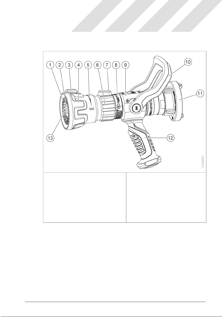
3.5 Overview ............................................................................ 10
4Delivery, transport, storage ..................................................... 11
4.1 Delivery .............................................................................. 11
4.2 Transport in a vehicle, storage .......................................... 11
5Use.............................................................................................. 12
5.1 Notes.................................................................................. 12
5.2 Handling............................................................................. 14
5.3 Visual inspection after each use ........................................ 17
6Functional test........................................................................... 18
6.1 Prerequisites ...................................................................... 18
6.2 Performing the inspection .................................................. 19
7Maintenance............................................................................... 20
7.1 Inspection and maintenance.............................................. 20
7.2 Repair ................................................................................ 20
7.3 Disposal ............................................................................. 22
8Accessories / spare parts......................................................... 23

AWG I Operating manual I Nozzles I Turbo nozzles EVO
INTRODUCTION
4 / 24
M1129B10 I Rev. 01-10/21
1 INTRODUCTION
This manual contains important information regarding your personal
safety. This manual must be read and understood by all persons who
handle or use the device during any phase of its life cycle.
The manual must be close at hand at the place of use throughout the
device's life cycle. All persons handling the device must be able to
consult the manual at any time. The manual must be handed over
along with the device when the device is sold.
1.1 Key to the symbols
This check mark indicates a prerequisite that must be fulfilled be-
fore a task can be carried out.
1. These numbered items list all the steps making up a task.
1.1.1 Safety Information
DANGER
Red signal bar and the signal word DANGER
Hazard with a high degree of risk, resulting in death or serious injury
if not avoided.
WARNING
Orange signal bar and the signal word WARNING
Hazard with a high degree of risk that may result in death or serious
injury if not avoided.
CAUTION
Yellow signal bar and the signal word CAUTION
Hazard with a low degree of risk that may result in minor injuries if
not avoided.

AWG I Operating manual I Nozzles I Turbo nozzles EVO INTRODUCTION
M1129B10 I Rev. 01-10/21 5 / 24
1.1.2 General information
IMPORTANT
Blue signal bar and the signal word IMPORTANT
Instructions on how to avoid damage to property. These instructions
are not related to potential physical injuries.
INFORMATION
This info box contains general information and tips for using
the device.
1.2 Figures
The illustrations in this manual are given by way of example. Differ-
ences between a technical illustration and the actual state of affairs are
therefore possible.
The text contains a reference to an illustration with the item number in
brackets: (Fig. 2/4) refers to Item 4in Figure 2.
Representation
The devices are shown in the illustrations with a Storz
adapter. Devices without adapters or with other adapters
will deviate from the illustrations.

AWG I Operating manual I Nozzles I Turbo nozzles EVO
SAFETY INFORMATION
6 / 24
M1129B10 I Rev. 01-10/21
2 SAFETY INFORMATION
The AWG turbo nozzles EVO described here are in line with the state
of the art as well as the recognised safety regulations. The safety and
health protection requirements have been met. Nevertheless, its use
may give rise to hazards for the user or third parties or cause damage
to the device itself or other material assets.
2.1 General safety instructions
The device may only be operated in accordance with these instruc-
tions and in perfect condition.
The operators must have received the necessary training to be able
to handle the device properly.
Unauthorized modifications or the installation of additional compo-
nents not approved by the manufacturer endanger the proper func-
tioning of the device.
– Modifications to the device are prohibited
– Only use accessories approved by the manufacturer
The operator is responsible for safety in the vicinity of the device, in
particular for compliance with the general safety regulations. This
includes ensuring, before using the device, that all protective devic-
es are fully in place and functional.
2.2 Safety during operation
Observe all safety rules and protective measures applicable for use
at the place of use.
Make sure the device does not get damaged during transport, in-
stallation, commissioning, operation or maintenance.
The safety regulations laid down in the country-specific service reg-
ulations for fire-fighters (for example in Germany the Feuerwehr-
dienstvorschrift FwDV) or the corresponding internal company regu-
lations must be observed.

AWG I Operating manual I Nozzles I Turbo nozzles EVO SAFETY INFORMATION
M1129B10 I Rev. 01-10/21 7 / 24
2.3 Qualifications of the operators
Persons handling or using the turbo nozzle EVO must be technically
qualified and trained. They must be aware of all risks involved in han-
dling the device.
The turbo nozzle EVO may only be used by persons who have been
trained and instructed in the operation of the device in accordance with
the country-specific fire service regulation (in Germany: FwDV) or cor-
responding internal company regulations.
Different qualifications are required for personnel performing the differ-
ent types of activity.
Instructed personnel:
Transport / use / cleaning as well as "Basic" functional testing
Technical personnel:
Maintenance as well as "Standard" and "Advanced" functional testing
2.4 Personal protective equipment
When using the AWG turbo nozzle EVOs, personal protective equip-
ment must be worn, in accordance with the country-specific fire service
regulation (e.g. in Germany: FwDV) or with internal company regula-
tions.

AWG I Operating manual I Nozzles I Turbo nozzles EVO
DESCRIPTION
8 / 24
M1129B10 I Rev. 01-10/21
3 DESCRIPTION
3.1 Function
With the AWG turbo nozzles EVO, a full jet or a spray jet from 0° to
120° can be generated at a selectable flow rate.
The extinguishing agent discharge is started and stopped with the
hand lever.
By turning the nozzle head (jet form sleeve) the spraying angle is
changed between full jet and the different settings for the spray jet.
Full jet If the jet pipe head is in the full jet position, a focused jet
with a long throwing distance and corresponding mechan-
ical penetration force of the water flow is achieved.
Spray jet In the other positions of the nozzle head, an atomised spray
jet covering an area is generated. The spectrum ranges
from a concentrated spray pattern to a wide filled spray
cone.
Rinsing In this position, dirt particles can be removed from the
nozzle in the direction of flow.
For models with a fixed sprocket in the jet form sleeve, the sprocket
ensures a filled spray cone by reflecting the water droplets. With mod-
els without a fixed sprocket, no water droplets are reflected, a hollow
conical spray is created (hollow jet).
The turbo wheel (optional), which rotates quickly in the spray jet, is
used for fine atomisation of the spray jet.
Extinguishing foam can be produced with an optional foam attachment.
With the optional FIRE-EX Turbo 1000 wetting agent cartridge, wetting
agent is generated directly in the hollow nozzle and applied with the
turbo nozzle EVO.
3.2 Intended use
Fire-fighting with both full jet and spray jet
When used with foam agent (with foam attachment accessory):
fighting fires involving non-polar liquids (petrol, oil)
Only use the device in technically sound condition and in accordance
with the intended purpose and with safety and potential dangers in
mind.

AWG I Operating manual I Nozzles I Turbo nozzles EVO
DESCRIPTION
M1129B10 I Rev. 01-10/21
9 / 24
3.3 Foreseeable misuse
Conversion or modification
Operation in technically unsound condition
Operation outside the approved characteristic values
Fitting of spare parts or accessories that are not approved or not
suitable for the operating conditions
Placing the nozzle in direct fire, embers or on hot surfaces
3.4 Characteristic values
Designation
Reference /
nominal
pressure
Flow rate grid
*
at reference pres-
sure
Spray angle
Turbo nozzle EVO 130
6/16bar
40/80/130
0° – 120°
Turbo nozzle EVO 235
6/16bar
60/130/235
0° – 120°
Turbo nozzle EVO 400
6/16bar
130/235/400
0° – 120°
Turbo nozzle EVO 750
6/16bar
360/550/750
0° – 120°
Turbo nozzle EVO 950
6/16bar
550/750/950
0° – 120°
* The flow rate grid designates the flow rate in [l/min] at the reference pressure in the
specified grid steps of the turbo nozzle EVO.
Test certificates
Certificates of conformity for the turbo nozzle EVO are
available from an independent testing institute.

AWG I Operating manual I Nozzles I Turbo nozzles EVO DESCRIPTION
10 / 24 M1129B10 I Rev. 01-10/21
3.5 Overview
Fig. 1 Overview of turbo nozzle EVO (example)
1
2
3
4
5
6
7
Fixed toothed ring (optional)
Valve plate
Protection ring pointer
Protection ring
Jet form sleeve scale
Flow rate of adjusting sleeve
Flow rate pointer
8
9
10
11
12
13
Flow rate scale
Housing
Hand lever
Fixed coupling
Hand grip
Turbo wheel (optional)

AWG I Operating manual I Nozzles I Turbo nozzles EVO
DELIVERY, TRANSPORT, STORAGE
M1129B10 I Rev. 01-10/21
11 / 24
4 DELIVERY, TRANSPORT, STORAGE
4.1 Delivery
The turbo nozzle EVO has been carefully packaged at AWG Fittings
GmbH.
After unpacking, check the delivery for damage and verify complete-
ness.
Any damage must be immediately reported to the carrier.
If parts are missing, immediately inform the responsible specialist
dealer or AWG Fittings GmbH.
The packaging material is recyclable, please dispose of it in an environ-
mentally-friendly manner.
Turbo nozzles EVO with a mounted coupling are ready for connection
and immediate use. For turbo nozzle EVO with a threaded connection,
a suitable coupling must be fitted by the dealer or customer before
commissioning.
4.2 Transport in a vehicle, storage
Turbo nozzle has run dry.
The turbo nozzle EVO can be transported and stored in any position.
Especially during transport in a vehicle, the turbo nozzle EVO must not
move around. If necessary, secure the turbo nozzle EVO using a belt.
During transport, the turbo nozzle EVO must not be damaged by other
heavy equipment.
To ensure proper functioning, the turbo nozzle EVO may only be
stored in a clean condition. The turbo nozzle EVO must not be stored
constantly pressurised with water.
We recommend open storage so that any residual water can drain off
and the seal of the shut-off unit is relieved.

AWG I Operating manual I Nozzles I Turbo nozzles EVO
USE
12 / 24
M1129B10 I Rev. 01-10/21
5 USE
5.1 Notes
WARNING
Hazards during use
The handling of foam agents can be hazardous to health.
The strength of the water jet can be dangerous.
– Wear personal protective equipment in accordance with country-
specific fire service regulations.
– Always wear eye protection.
– Do not point it at people or animals.
CAUTION
Attach adapters correctly
Danger of injury due to loosening of adapter connections.
– Always insert the adapters up to the stop and couple them fully.
CAUTION
Reaction forces
Depending on the inlet pressure, reaction forces may occur during
operation.
– Safe handling must be ensured. If necessary, the nozzle must be
held by several persons (see country-specific fire service regula-
tions).
– Increased recoil forces can occur especially when switching to the
flushing position.

AWG I Operating manual I Nozzles I Turbo nozzles EVO USE
M1129B10 I Rev. 01-10/21 13 / 24
IMPORTANT
Product information for foam concentrates
Observe the information on health hazards and potential environ-
mental hazards (e.g. water hazard class) provided in the safety data
sheet and other product information for the foam concentrates used.
Use of different foam concentrates
Note the compatibility of different foam concentrates.
Hand grip
The turbo nozzle EVO can be operated without a handle (de-
scription of assembly/disassembly in Chapter 7.2). The func-
tion of the nozzle is not affected.
With turbo nozzles EVO from Qmin = 500 l/min, the continuous
M6 threaded hole must be closed with a M6x6 threaded pin
and glued in tightly. If the threaded holes are not drilled
through, screw in a threaded pin as protection against con-
tamination.
Extinguishing in electrical installations /rated voltage up to 380 kV *
If the control distances according to DIN VDE 0132, Table 3: guideline
values H-5-10, are adhered to, a full jet of water from the turbo nozzle
EVO in the highest flow position has sufficient resistance according to
DIN VDE 0132 to prevent a voltage flash-over at high voltages of up to
380 kV.
For low voltage up to 1 kV, the guide values N-1-5 must be observed.
* Test report of an accredited test laboratory according to DIN EN ISO/IEC 17025 is
available

AWG I Operating manual I Nozzles I Turbo nozzles EVO
USE
14 / 24
M1129B10 I Rev. 01-10/21
Distances according to DIN VDE 0132, Table 3
Nozzle
DIN 14365-CM
Low voltage (N)
≤AC 1
kV or ≤DC 1.5
kV
High voltage (H)
> AC 1
kV or > DC 1.5
kV
Spray jet 1 m 5 m
Full jet 5 m 10 m
Letter symbol N-1-5 H-5-10
WARNING
Danger from electric shock
The use on live electrical installations can result in life-threatening
electric shock.
– When extinguishing in electrical installations, observe the pre-
scribed control distances and guideline values as well as the flow
position.
– Only use foam agents when electrical systems are disconnected.
5.2 Handling
Required inlet pressure
At an inlet pressure below the reference pressure of 6 bar,
the flow rates indicated on the nozzle are not achieved
Ensure a sufficient flow rate and inlet pressure for the re-
spective extinguishing situation.
The water hose for connection to the fixed coupling of the turbo
nozzle EVO is ready at hand.
The hand lever is closed (Fig. 2/A).
When used with foam agent: The inductor and foam attachment are
mounted.

AWG I Operating manual I Nozzles I Turbo nozzles EVO USE
M1129B10 I Rev. 01-10/21 15 / 24
1
2
3
4
Protection ring
Jet form sleeve scale
Flow rate of adjusting sleeve
Flow rate scale
5
6
7
Hand lever
Turbo nozzle EVO fixed coupling
Water hose adapter
Fig. 2 Handling
Coupling the turbo nozzle EVO and adjusting the flow rate
1. By hand or with the use of a suitable coupling spanner, attach the
coupling of the water hose (Fig. 2/7) to the coupling on the turbo
nozzle EVO (Fig. 2/6).
2. Set the adjusting sleeve (Fig. 2/3) to the desired flow rate (Fig. 2/4).
The pointer is in the middle position at the top, on the right
(2 o'clock position) for the small flow rate and on the left (10 o'clock
position) for the large flow rate.
Attention: Turn the adjusting sleeve anti-clockwise beyond the
maximum position to set the flushing position. The pointer is at the
bottom (7 o'clock position). Do not use the flushing position in the
extinguishing insert unintentionally. The flushing position is clearly
visible through several detent points.
3. Open the water supply.
The turbo nozzle EVO is ready for use.

AWG I Operating manual I Nozzles I Turbo nozzles EVO USE
16 / 24 M1129B10 I Rev. 01-10/21
Opening the turbo nozzle EVO and starting the extinguishing
agent discharge
1. Point the turbo nozzle EVO at the source of the fire.
2. Pull the hand lever (Fig. 2/5) back towards yourself in the OPEN
(Fig. 2/B) position.
The extinguishing agent discharge is started. As soon as the hand
lever is moved forward again to the CLOSED (Fig. 2/A) position,
the extinguishing agent discharge stops.
Varying the spray angle
1. By turning the protection ring (Fig. 2/1) you can switch between full
and spray jet during use:
Full jet Narrow spray jet Wide spray jet
The three positions are audibly and clearly noticeably fixed by locking
in place.
Close the turbo nozzle EVO
1. Push the hand lever (Fig. 2/5) forward to the CLOSED (Fig. 2/A)
position away from the body.
Flushing out the turbo nozzle EVO
1. Close the turbo nozzle EVO (CLOSED position).
2. When using foam concentrates, interrupt their supply.
3. Turn the adjusting sleeve (Fig. 2/3) into the flushing position (turn
the adjusting sleeve beyond the maximum position to the 7 o'clock
position).
4. Open the turbo nozzle EVO (OPEN position).
The flushing position can be noticed when the turbo nozzle EVO
rattles. Dirt particles up to 5 mm diameter are rinsed out.

AWG I Operating manual I Nozzles I Turbo nozzles EVO USE
M1129B10 I Rev. 01-10/21 17 / 24
Perform multiple flushes if necessary.
Flushing process during use
A flushing process may also be necessary during use if dirt
particles get into the turbo nozzle EVO. This can be recog-
nised by an uneven, disturbed spray pattern.
In this case you can switch directly to the flushing position:
– Turn the adjusting sleeve into the flushing position and
flush it out for as long as necessary.
Attention: Only rinse if the situation in use allows it (observe
self-protection).
Uncouple the turbo nozzle EVO
1. When using foam concentrates, interrupt their supply.
2. Close the hand lever and the water supply.
3. Open the turbo nozzle EVO to reduce the pressure.
Attention When you open the turbo nozzle EVO, water comes out.
4. By hand or with the use of a coupling spanner, release the coupling
of the water hose (Fig. 2/7) to the fixed coupling on the turbo nozzle
EVO (Fig. 2/6).
Attention Water may emerge when the couplings are released.
5.3 Visual inspection after each use
The turbo nozzle EVO is separated from the water supply.
The turbo nozzle EVO must not be contaminated with foam agent.
If necessary, flush the turbo nozzle EVO again as described in the
previous section.
1. Check the turbo nozzle EVO and, in particular, the toothed ring and
the valve plate on the nozzle head for visible damage.
Attention If you discover any damage, this must be reported to
the person or department responsible.
2. Check that the hand lever as well as the adjusting sleeve and the
nozzle head of the turbo nozzle EVO can be operated (unpressur-
ised).

AWG I Operating manual I Nozzles I Turbo nozzles EVO FUNCTIONAL TEST
18 / 24 M1129B10 I Rev. 01-10/21
6 FUNCTIONAL TEST
6.1 Prerequisites
All testing of the AWG turbo nozzle EVO must be carried out in ac-
cordance with the manufacturer's technical documentation and must
be documented if necessary.
The following inspections are defined for the turbo nozzle EVO:
– Mandatory BASIC Inspection after each use
– Mandatory STANDARD Inspection every 12 months
– Optional ADVANCED Inspection every 12 months
The STANDARD and ADVANCED inspections may only be carried out
by qualified personnel who have been trained for these inspections:
– Fire-fighters who have received training as fire-fighting equip-
ment maintenance technicians or persons with equivalent quali-
fications
– or, if desired, directly by the manufacturer
Inspection by the manufacturer
AWG Fittings GmbH offers an inspection as part of its service offering.
Send us the turbo nozzle EVO, and you will receive the inspected de-
vice back at the agreed date. You will find a return delivery form on our
website www.awg-fittings.com. If required, a rental device can also be
provided.
Documenting the inspection result
To meet the requirements for occupational safety and acci-
dent prevention, the test results for each test must be doc-
umented. Please observe the country-specific regulations.
For Germany you will find a test chart in accordance with the
DGUV (German statutory accident insurance) requirements
as download from www.awg-fittings.com
– Keep the documented test result as proof.

AWG I Operating manual I Fittings I Turbo nozzles EVO
FUNCTIONAL TEST
M1129B10 I Rev. 01-10/21
19 / 24
6.2 Performing the inspection
CAUTION
Performing the inspection safely
Some inspection steps are performed with pressurised systems.
– Observe the safety regulations.
– Put on personal protective equipment.
– Do not put other persons in danger.
6.2.1 BASIC Inspection after each use
1. Check the turbo nozzle EVO for visible damage.
2. Check the toothed ring and valve plate on the nozzle head for con-
tamination and damage.
3. Check that the hand lever can be operated (unpressurised).
4. Check that the nozzle head and the adjusting sleeve can be oper-
ated.
5. Check whether the nozzle inlet can be freely rotated through 360°.
6.2.2 STANDARD Inspection every 12 months
1. Functional test of the hand lever under dynamic load at 10 bar inlet
pressure.
2. Leak test at 10 bar inlet pressure (hand lever in closed position).
3. Check the toothed ring and valve plate on the nozzle head for damage.
6.2.3 ADVANCED Inspection every 12 months
Check the coupling torque of the Storz adapter:
Threshold valueStorz 25 (D): 1.5 Nm
Storz 52 (C): 1.5 Nm
Storz 75 (B): 2.5 Nm
If the coupling torque is below the applicable threshold value,
the adapter must be replaced.
Threaded version: Check the thread for heavy wear and tear.
Replace device if worn.

AWG I Operating manual I Nozzles I Turbo nozzles EVO MAINTENANCE
20 / 24 M1129B10 I Rev. 01-10/21
7 MAINTENANCE
7.1 Inspection and maintenance
Apart from the visual inspection and cleaning of the AWG turbo nozzle
EVO, no regular maintenance work is required.
If the shut-off device is hard to operate, lubricate the ball valve with a
fully synthetic grease for food technology (e.g. OKS 479).
7.2 Repair
1
2
3
4
5
6
Threaded holes
Hand grip
Cylinder screws
Lid
Screw caps
Cylinder screws
7
8
9
10
11
12
Hand lever
Threaded pin
Protection ring
Turbo wheel
Toothed ring
Cylinder screws
Fig. 3 Replacing the handle and hand lever
This manual suits for next models
5
Table of contents
Popular Paint Sprayer manuals by other brands

EUROPRO
EUROPRO JETPRO 80 user manual

AirPlus
AirPlus Air Plus Spray Schulz instruction manual

Earth Way
Earth Way SPRAY-PRO S15 Assembly and operating instructions

Central Pneumatic
Central Pneumatic 90985 Assembly and operating instructions

Metrix
Metrix HI-913 installation manual

Hudson
Hudson Bak-Pak 13194 Product instructions

Central Pneumatic
Central Pneumatic 66871 Set up and operating instructions

OneTech
OneTech NT10-R-77Z-20 Manual instruction

Emist
Emist EPIX360 user manual

Powr-Flite
Powr-Flite PP200-Q02-U Operation and maintenance manual

Worx Nitro
Worx Nitro HYDROSHOT WG633E instructions

R+M Suttner
R+M Suttner ST-3100 operating instructions