Axcera 605C User manual


September 4, 2009
INTRODUCTION
A. REFERENCE MATERIAL
SYSTEM....................................................................... 1587-1001(2.3-2.4GHz),
1587-1002(2.076-2.11GHz),
1587-1003(2.1-2.3GHz),
or 1587-1004(2.5-2.7GHz)
A. SYSTEM DESCRIPTION
B. SPECIFICATIONS
C. UNPACKING AND INSTALLATION
D. SYSTEM CHECK-OUT AND OPERATION PROCEDURES
E. FRONT PANEL
F. LED INDICATORS
G. DRAWINGS
1. SYSTEM BLOCK DIAGRAM...............................................1576-3000
2. SYSTEM INTERCONNECT ................................................1576-8000
3. SYSTEM REPLACEMENT PART LIST............... 1587-1001(2.3-2.4GHz),
1587-1002(2.076-2.11GHz),
1587-1003(2.1-2.3GHz),
or 1587-1004(2.5-2.7GHz)
4. BOOSTER BLOCK DIAGRAM ............................................1576-3100
5. BOOSTER ASSEMBLY DRAWING ......................................1576-5100
6. BOOSTER INTERCONNECT..............................................1576-8100
7. BOOSTER REPLACEMENT PART LIST ............ 1587-1100(2.3-2.4GHz),
1587-1101(2.076-2.11GHz),
1587-1102(2.1-2.3GHz),
or 1587-1103(2.5-2.7GHz)
MAINTENANCE AND TROUBLESHOOTING
605C BOOSTER
TABLE OF CONTENTS

REFERENCE 605C BROADBAND BOOSTER
EMERGENCY FIRST AID INSTRUCTIONS
Personnel engaged in the installation, operation, or maintenance of this equipment are urged to become familiar with the following
rules both in theory and practice. It is the duty of all operating personnel to be prepared to give adequate Emergency First Aid and
thereby prevent avoidable loss of life.
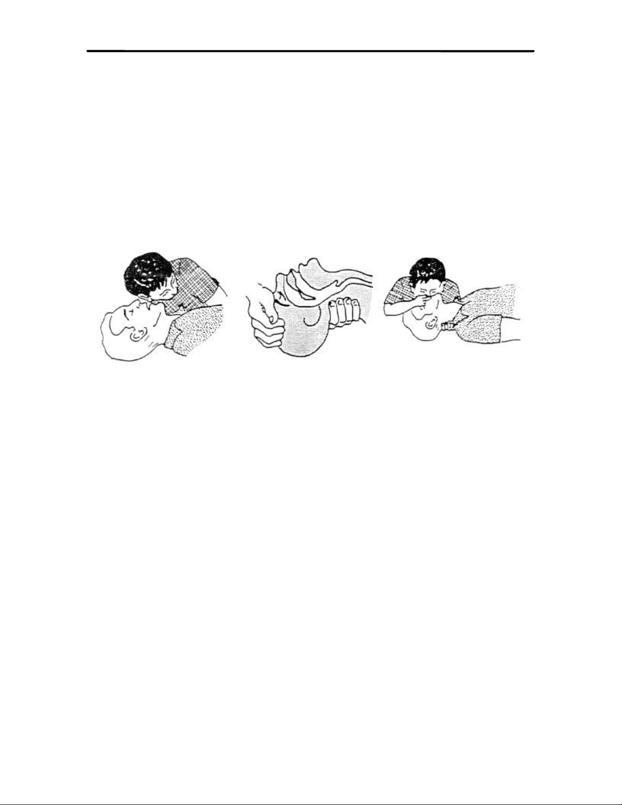
RESCUE BREATHING
1. Find out if the person is breathing.
You must find out if the person has
stopped breathing. If you think he is not
breathing , place him flat on his back. Put
your ear close to his mouth and look at his
chest. If he is breathing you can feel the
air on your cheek. You can see his chest
move up and down. If you do not feel the
air or see the chest move, he is not
breathing.
2. If he is not, open the airway by tilting
his head backwards.
Lift up his neck with one hand and push
down on his forehead with the other. This
opens the airway. Sometimes doing this
will let the person breathe again by
himself. If is does not, begin rescue
breathing.
3. If he is still not breathing, begin rescue
breathing.
-Keep his head tilted backward. Pinch
nose shut.
-Put your mouth tightly over his mouth.
-Blow into his mouth once every five
seconds
-DO NOT stop rescue breathing
breathing until help comes.
LOOSEN CLOTHING - KEEP WARM
Do this when the victim is breathing by
himself or help is available. Keep him as
quiet as possible and from becoming
chilled. Otherwise treat him for shock.
BURNS
SKIN REDDENED: Apply ice cold water to burned area to
prevent burn from going deeper into skin tissue. Cover area with
clean sheet or cloth to keep away air. Consult a physician.
SKIN BLISTERED OR FLESH CHARRED: Apply ice cold
water to burned area to prevent burn from going deeper into skin
tissue. Cover area with clean sheet or cloth to keep away air.
Treat victim for shock and take to hospital.
EXTENSIVE BURN - SKIN BROKEN: Cover area with clean
sheet or cloth to keep away air. Treat victim for shock and take
to hospital.
WARNING!!!
DO NOT ATTEMPT TO REPAIR OR TROUBLESHOOT THIS EQUIPMENT UNLESS YOU
ARE FAMILIAR WITH ITS OPERATION AND EXPERIENCED IN SERVICING HIGH
VOLTAGE EQUIPMENT. LETHAL VOLTAGES ARE PRESENT WHEN POWER IS APPLIED
TO THIS SYSTEM. IF POSSIBLE, TURN OFF POWER BEFORE MAKING ADJUSTMENTS
TO THE SYSTEM.

REFERENCE 605C BROADBAND BOOSTER
LIMITED WARRANTY
ONE YEAR
Seller warrants each new product manufactured and sold by Seller against defects in material and
workmanship under normal use and service, for a period of one (1) year from the date of shipment from
Seller's plant, when operated in accordance with Seller's operating instructions. This warranty shall not
apply to tubes, fuses, batteries, or bulbs.
Warranties are valid only when and if (a) Seller receives prompt written notice of breach within the
period of warranty, (b) the defective product is properly packed and returned by the Buyer (transportation
and insurance prepaid), and (c) Seller determines, in its sole judgment, that the product is defective and
not subject to any misuse, neglect, improper installation, negligence, accident, or (unless authorized in
writing by Seller) repair or alteration. Seller's exclusive liability for any personal and/or property damage
(including direct, consequential or incidental) caused by the breach of any or all warranties, shall be
limited to the following: (a) repairing or replacing (in Seller's sole discretion) any defective parts free of
charge (F.O.B. Seller's plant), and/or (b) crediting (in Seller's sole discretion) all or a portion of the
purchase price to the Buyer.
Equipment furnished by Seller, but not bearing its trade name, shall bear no warranties other than the
special hours-of-use or other warranties extended by or enforceable against the manufacturer at the time
of delivery to the buyer. NO WARRANTIES, WHETHER STATUTORY, EXPRESSED OR
IMPLIED, AND NO WARRANTIES OF MERCHANTABILITY, FITNESS FOR ANY
PARTICULAR PURPOSE, OR FREEDOM FROM INFRINGEMENT, OR THE LIKE, OTHER
THAN AS SPECIFIED IN PATENT LIABILITY ARTICLES, AND IN THIS ARTICLE, SHALL
APPLY TO THE EQUIPMENT FURNISHED HEREUNDER.
• 103 Freedom Drive P.O. Box 525, Lawrence, PA 15055-0525 USA • 724-873-8100 • FAX 724-873-8105

REFERENCE 605C BROADBAND BOOSTER
)MATERIAL RETURN PROCEDURE
In order to efficiently handle equipment or components returned for repair or sent out on
loan, Axcera requests that each returned item be accompanied by a Material Return
Authorization Number (MRA#).
To obtain an MRA follow the procedures below:
pCall Axcera Customer Service at (724)-873-8100
or FAX (724) 873-8105
pA Service Engineer will provide you with an MRA#
pWrite the MRA# on the packing list or in the case of repairs, a
note describing the reason for return. Also, be sure to include contact
information.
pSend ALL MRA items to the following address
Axcera, LLC
103 Freedom Drive, P.O. Box 525
Lawrence, PA 15055-0525
%TELEPHONE TECHNICAL SUPPORT
Axcera currently provides free telephone technical support. When calling, be prepared to
provide the following information:
pTransmitter model # AND Serial #
pStatus of front panel LED’s (are any red LED’s on ?)
pHave a copy of your operation manual ready prior to calling
From 8:00 AM - 5:00 PM EST call (724) 873-8100 for technical support

REFERENCE 605C BROADBAND BOOSTER
PROPER PACKING OF MATERIALS
When returning materials to Axcera, it is extremely important to pack them properly. Due
to the delicate nature of components contained within the equipment, major damage can
occur without proper packing. Please adhere to the following guidelines when returning
materials.
oSave the boxes that the transmitter is shipped in. Each tray is sent
double boxed and enclosed in foam padding. Use the same packing
method when returning materials.
Failure to properly pack any returned materials may result in damage to the
equipment. Axcera is not responsible for damaged equipment under these
circumstances. Many freight companies will not compensate for damages when
items are not packed properly. Please pack items properly!

REFERENCE 605C BROADBAND BOOSTER
dBm, dBw, dBmV, dBµV, AND VOLTAGE EXPRESSED IN WATTS
50 ohm system
WATTS PREFIX dBm dBw dBmV dBµVVOLTAGE
1,000,000,000,000 1 TERAWATT +150 +120
100,000,000,000 100 GIGAWATTS +140 +110
10,000,000,000 10 GIGAWATTS +130 +100
1,000,000,000 1 GIGAWATT +120 + 99
100,000,000 100 MEGAWATTS +110 + 80
10,000,000 10 MEGAWATTS +100 + 70
1,000,000 1 MEGAWATT + 90 + 60
100,000 100 KILOWATTS + 80 + 50
10,000 10 KILOWATTS + 70 + 40
1,000 1 KILOWATT + 60 + 30
100 1 HECTROWATT + 50 + 20
50 + 47 + 17
20 + 43 + 13
10 1 DECAWATT + 40 + 10
1 1 WATT + 30 0+ 77 +137 7.07V
0.1 1 DECIWATT + 20 - 10 + 67 +127 2.24V
0.01 1 CENTIWATT + 10 - 20 + 57 +117 0.707V
0.001 1 MILLIWATT 0- 30 + 47 +107 224mV
0.0001 100 MICROWATTS - 10 - 40
0.00001 10 MICROWATTS - 20 - 50
0.000001 1 MICROWATT - 30 - 60
0.0000001 100 NANOWATTS - 40 - 70
0.00000001 10 NANOWATTS - 50 - 80
0.000000001 1 NANOWATT - 60 - 90
0.0000000001 100 PICOWATTS - 70 -100
0.00000000001 10 PICOWATTS - 80 -110
0.000000000001 1 PICOWATT - 90 -120
TEMPERATURE CONVERSION
°F = 32 + [(9/5) °C]
°C = [(5/9) (°F - 32)]

REFERENCE 605C BROADBAND BOOSTER
USEFUL CONVERSION FACTORS
TO CONVERT FROM TO MULTIPLY BY
mile (US statute) kilometer (km) 1.609347
inch (in) millimeter (mm) 25.4
inch (in) centimeter (cm) 2.54
inch (in) meter (m) 0.0254
foot (ft) meter (m) 0.3048
yard (yd) meter (m) 0.9144
mile per hour (mph) kilometer per hour(km/hr) 1.60934
mile per hour (mph) meter per second (m/s) 0.44704
pound (lb) kilogram (kg) 0.4535924
gallon (gal) liter 3.7854118
U.S. liquid
(One U.S. gallon equals 0.8327 Canadian gallon)
fluid ounce (fl oz) milliliters (ml) 29.57353
British Thermal Unit watt (W) 0.2930711
per hour (Btu/hr)
horsepower (hp) watt (W) 746
NOMENCLATURE OF FREQUENCY BANDS
FREQUENCY RANGE DESIGNATION
3 to 30 kHz VLF - Very Low Frequency
30 to 300 kHz LF - Low Frequency
300 to 3000 kHz MF - Medium Frequency
3 to 30 MHz HF - High Frequency
30 to 300 MHz VHF - Very High Frequency
300 to 3000 MHz UHF - Ultrahigh Frequency
3 to 30 GHz SHF - Superhigh Frequency
30 to 300 GHz EHF - Extremely High Frequency
LETTER DESIGNATIONS FOR UPPER FREQUENCY BANDS
LETTER FREQ. BAND
L 1000 - 2000 MHz
S 2000 - 4000 MHz
C 4000 - 8000 MHz
X 8000 - 12000 MHz
Ku 12 - 18 GHz
K 18 - 27 GHz
Ka 27 - 40 GHz
V 40 - 75 GHz
W 75 - 110 GHz

REFERENCE 605C BROADBAND BOOSTER
ABBREVIATIONS/ACRONYMS
AC Alternating Current
AFC Automatic Frequency Control
ALC Automatic Level Control
AM Amplitude modulation
AGC Automatic Gain Control
AWG American wire gauge
BER Bit Error Rate
BW Bandwidth
DC Direct Current
D/A Digital to analog
dB Decibel
dBm Decibel referenced to 1 milliwatt
dBmV Decibel referenced to 1 millivolt
dBw Decibel referenced to 1 watt
FEC Forward Error Correction
FM Frequency modulation
Hz Hertz
ICPM Incidental Carrier Phase Modulation
I/P Input
IF Intermediate Frequency
LED Light emitting diode
LSB Lower Sideband
MPEG Motion Pictures Expert Group
O/P Output
PLL Phase Locked Loop
PCB Printed circuit board
QAM Quadrature Amplitude Modulation

REFERENCE 605C BROADBAND BOOSTER
RETURN LOSS VS. VSWR
1.001 1.01 1.1 2.0
0
-10
-20
-30
-40
-50
-60
-70
R
E
T
U
R
N
L
O
SS
dB

SYSTEM 605C BROADBAND BOOSTER
BROADBAND BOOSTER 605C
DESCRIPTION
The 605C Broadband Booster repeats multiple RF Channels in the 2076-2686 MHz frequency range. It is
characterized for both analog NTSC/PAL and digital performance. An automatic level control circuit
maintains constant output over a 30 dB input range. Input filters eliminate out-of-band retransmission. An
output circulator provides VSWR protection.


SYSTEM 605C BROADBAND BOOSTER
INSTALLATION PROCEDURE 605C
UNPACKING
Please inspect all material thoroughly upon arrival. Axcera certifies that upon leaving our facility the
equipment was undamaged and in proper working order. The shipping container should be inspected for
obvious damage indicative of rough handling.
Remove the booster from the shipping container and inspect for damage. Check for dents, and scratches, or any
broken connectors. Extract all packing material from inside and around the unit. Check for loose hardware and
connectors, retighten if needed. Any claims against in-transit damage should be directed to the carrier. Save all
packing material in case it is needed in the future.
INSTALLATION OF BOOSTER
íThe 605C is designed as a pole mount device, however, it may also be mounted on the side of a building
or most any other desired location. For pole mount applications, an Installation Material Kit including a
mounting bracket, U-bolts, and other necessary hardware is provided. Refer to the "Pole Mounting
Details Drawing" which follows, for complete instructions.
íLocation of the receive antenna in respect to the transmit antenna is critical. Every situation is unique,
therefore it is necessary for system design to be considered. If the system is configured such that both
antennas are on the same tower, then vertical separation is necessary. The distance will depend on the
antennas being used and their location, transmit on top receive on bottom or vise versa. For other
configurations, typically some type of shielding is used. Consult with your system designer for specific
details pertaining to your site.
íAfter the unit is physically in place, the process of interfacing them into the system begins by making
connections to the bottom of the booster.
POLE MOUNTING DETAILS DRAWING

SYSTEM 605C BROADBAND BOOSTER
CONNECTIONS
Cable selection is a very critical part of the installation. Several optional power kits are available from Axcera.
In the event cables are purchased from another supplier, please consult with your system designer prior to
purchase. Use of incorrect cables may result in substantial signal loss or cause interference to other devices.
Consider all of the following connections when selecting cable.
CONNECTION
(cable type will vary based on site specifications)
RF INPUT (J1)
RF OUTPUT (J2)
POWER IN (J3)
POWER LOOP THRU (J4)
PRE AMP POWER (J6)
EXTERNAL CONTROL (J7)
REMOTE DIAGNOSTICS (J8)
Also, pay close attention to loss on cables that are substantial in length. This could have a major impact on
circuit behavior.

OPERATION 605C BROADBAND BOOSTER
INITIAL TURN ON
Prior to turning on the system, be sure all connections are in the correct place Next, follow the steps below:
íTurn the external power supply on.
íVerify green LED’s DS1-DS4 on the ±12V/-5V Power Supply Board are lit..
íIf the optional remote operate/standby feature is not used, move J11 on the
Booster Control Board to the OPR LOCK position. If the feature is used, the
jumper should be in the RMT OPR position.
íMove switch S1 on the Booster Control Board to the operate position.
íCheck the position of switch SW2 on the Booster Control Board to verify it is in
the ALC position.
íThe output power of the booster can be adjusted with R42 on the Booster Control
Board.

OPERATION 605C BROADBAND BOOSTER
BOTTOM VIEW 605C
RF I/P (J1) Provides an RF input to the unit
RF O/P (J2) Provides an RF output from the unit
PWR IN (J3) Power in to the unit
PWR LOOP THRU (J4) Power outlet used to supply secondary units
RF SAMPLE (J5) Provides an RF sample from the unit
PRE AMP PWR (J6) Provides DC voltage to the preamp
EXT CONTROL (J7) For external switching from operate to standby
REMOTE DIAGNOSTICS (J8) Provides remote monitoring ability

BOOSTER 605C BROADBAND BOOSTER
INTERNAL LED INDICATORS 605C
ASSEMBLY NAME LED INDICATES
BIAS PROTECTION
BOARD DS1-GREEN BIAS CURRENT
BOOSTER CONTROL
BOARD DS1-GREEN THERMAL INTERLOCK
BOOSTER CONTROL
BOARD DS3-GREEN OPERATE
BOOSTER CONTROL
BOARD DS2-RED OVERDRIVE
BOOSTER CONTROL
BOARD DS4-RED LOW OUTPUT
±12V/±5V POWER
SUPPLY BOARD DS1-GREEN PROPER VOLTAGE FROM REGULATOR
±12V/±5V POWER
SUPPLY DS2-GREEN PROPER VOLTAGE FROM REGULATOR
±12V/±5V POWER
SUPPLY DS3-GREEN PROPER VOLTAGE FROM REGULATOR
±12V/±5V POWER
SUPPLY DS4-GREEN PROPER VOLTAGE FROM REGULATOR
* NOTE - ALL GREEN LED'S SHOULD BE ILLUMINATED WHEN THE BOOSTER IS OPERATING.
RED LED'S SHOULD NOT BE ON AT ANY TIME.


Table of contents