Axia iQ Operation manual

iQ Console System
Installation & User’s Guide
Manual Rev 1.3.1 — June, 2014
for iQ v1.00 and higher
p/n 1490-00067-001

USA Class A Computing Device
Information To User. Warning:
This equipment generates, uses, and can radiate ra-
dio-frequency energy. If it is not installed and used
as directed by this manual, it may cause interference
to radio communication. This equipment complies
with the limits for a Class A computing device, as
specied by FCC Rules, Part 15, Subpart J, which
are designed to provide reasonable protection against
such interference when this type of equipment is op-
erated in a commercial environment. Operation of
this equipment in a residential area is likely to cause
interference. If it does, the user will be required to
eliminate the interference at the user’s expense.
NOTE: Objectionable interference to TV or radio re-
ception can occur if other devices are connected to
this device without the use of shielded interconnect
cables. FCC rules require the use of only shielded
cables.
Canada Warning:
“This digital apparatus does not exceed the Class A
limits for radio noise emissions set out in the Radio
Interference Regulations of the Canadian Depart-
ment of Communications.” “Le present appareil
numeriQue n’emet pas de bruits radioelectriQues
depassant les limites applicables aux appareils nu-
meriQues (de les Class A) prescrites dans le Regle-
ment sur le brouillage radioelectriQue edicte par le
ministere des Communications du Canada.”
CE Conformance Information:
This device complies with the requirements of the
EEC Council Directives: 93/68/EEC (CE Marking);
73/23/EEC (Safety – low voltage directive); 89/336/
EEC (electromagnetic compatibility). Conformity is
declared to those standards: EN50081-1, EN50082-1.
Important Safety Information
To prevent risk of electric shock: Disconnect power
cord before servicing. If fuse replacement is required,
please note: For continued protection against re, re-
place fuse only with same type and value.
Caution
The installation and servicing instructions in the
manual are for use by qualied personnel only. To
avoid Electric Shock, do not perform any servicing
other than that contained in the operating instruc-
tions unless you are qualied to do so. Refer all ser-
vicing to qualied personnel.
Electrical Warning
To reduce the risk of electrical shock, do not expose
this product to rain or moisture. Keep liquids away
from the ventilation openings in the top and rear of
the unit. Do not shower or bathe with the unit.
This equipment is designed to be operated from a
power source that includes a third “grounding” con-
nection in addition to the power leads. Do not defeat
this safety feature. In addition to creating a potential-
ly hazardous situation, defeating this safety ground
will prevent the internal line noise lter from func-
tioning.
Ventilation Warning
The Axia QOR.32 requires the free ow of air for
adequate cooling. Do not block the ventilation open-
ings in the top and rear of the unit. QOR.32 must be
mounted with a blank rack space above or damage
may occur.
Failure to allow proper ventilation could damage the
unit or create a re hazard. Do not place the units on
a carpet, bedding, or other materials that could inter-
fere with any panel ventilation openings.

Introduction • iii
© 2014 Axia Audio - Rev 1.3.1
Customer Service
We support you...
By Phone/Fax.
• You may reach our 24/7 Support Team anytime around the clock by calling +1 216-622-0247. For billing
questions or other non-emergency technical questions, call +1 216-241-7225 between 9:30 AM to 6:00 PM
USA Eastern Time, Monday through Friday.
By E-Mail.
• Non-emergency technical support is available at Support@AxiaAudio.com.
Via World Wide Web.
• The Axia Web site has a variety of information which may be useful for product selection and support. The
URL is http://www.AxiaAudio.com.
Feedback
We welcome feedback on any aspect of the Livewire products or this manual. In the past, many good ideas from
users have made their way into software revisions or new products. Please contact us with your comments.
Updates
The operations of iQ and QOR.32 are determined largely by software. Periodic updates may become available -
to determine if this is the case, visit our web site periodically, or contact us for advice concerning whether a newer
release is more suitable to your needs.
We recommend joining the Axia Tech mailing list to ensure that you receive immediate updates regarding
new software or documentation releases. You can do so by clicking the “Sign Up Here” links at the top of the
Axia Download and Manuals pages at AxiaAudio.com/manuals/ and AxiaAudio.com/downloads/.
Trademarks
Livewire is a trademark of TLS Corporation. All other trademarks are the property of their respective holders.
Axia Audio
1241 Superior Ave. Cleveland, OH 44114 USA
+1 (216) 241-7225
Inquiry@AxiaAudio.com
Copyright © 2014 by TLS Corporation. Published by Axia Audio. We reserve the right to make improvements or changes in the prod-
ucts described in this manual, which may affect the product specications, or to revise the manual without notice. All rights reserved.

Introduction • iv
© 2014 Axia Audio - Rev 1.3.1
Notice
All versions, claims of compatibility, trademarks, etc.
of hardware and software products not made by Axia
mentioned in this manual or accompanying material
are informational only. Axia makes no endorsement
of any particular product for any purpose, nor claims
any responsibility for operation or accuracy.
Warranty
This product is covered by a Two Year limited war-
ranty, the full text of which is included in the rear
section of this manual.
Service
You must contact Axia before returning any equip-
ment for factory service. Axia will issue a Return
Authorization number, which must be written on the
exterior of your shipping container. Please do not
include cables or accessories unless specically re-
quested by the Technical Support Engineer at Axia.
Be sure to adequately insure your shipment for its
replacement value. Packages without proper authori-
zation may be refused. US customers please contact
Axia technical support at +1 (216) 241-7225. All oth-
er customers should contact their local representative
to arrange for service.
We strongly recommend being near the unit when
you call, so our Support Engineers can verify infor-
mation about your conguration and the conditions
under which the problem occurs. If the unit must
return to Axia, we will need your serial number, lo-
cated on the rear panel.
Credit Where Credit’s Due
Thanks to the great folks on the Axia team who
produced a great product and helped to compile this
manual - Denny, Gints, Maciej, Marc, Maris, Marty,
Milos, Oleg — we are honored to work with all of
you. cn and bw.
Feedback is welcome
At Axia, we love to hear your feedback. If you nd
anything in this manual that you feel needs clarica-
tion or correction, please let us know by sending an
e-mail to cnovak@AxiaAudio.com .
About This Manual
This manual covers the details of the iQ Frames
and QOR.32. Axia’s iQ is designed to operate as a
standalone console however it also has network ca-
pabilities. To learn more about these concepts, you
may wish to read Introduction to Livewire: System
Design Reference and Primer and Audio Over IP:
Building Pro AoIP Systems with Livewire by Steve
Church and Skip Pizzi, available from Elsevier Press.
In these publications we explain the ideas that mo-
tivated Livewire and how you can use and benet
from it, as well as nitty-gritty details about wiring,
connectors, and the like. Since Livewire is built on
standard networks, we also help you to understand
general network engineering so that you have the full
background for Livewire’s fundamentals. After read-
ing this reference material, you will know what’s up
when you are speaking with the network guys that
are often hanging around radio stations these days.
Although we strive for accuracy, some features and
operational characteristics may differ in actual use
from their descriptions herein. We invite feedback
and corrections from our clients.
Axia Audio
1241 Superior Avenue
Cleveland Ohio 44114 USA
Phone: +1.216.241.7225
Web: www.AxiaAudio.com
E-Mail: Inquiry@AxiaAudio.com

Introduction • v
© 2014 Axia Audio - Rev 1.3.1
Table of Contents
Customer Service . . . . . . . . . . . . . . . . . .iii
Warranty . . . . . . . . . . . . . . . . . . . . . . iv
Service . . . . . . . . . . . . . . . . . . . . . . . iv
Credit Where Credit’s Due . . . . . . . . . . . . .iv
About This Manual . . . . . . . . . . . . . . . . . iv
A Note From The CEO of Telos. . . . . . . . . . .vii
Getting Started . . . . . . . . . . . . . . . . . . . . . . 1
Chapter One: Setup And Connections . . . . . . . . . 3
Introduction . . . . . . . . . . . . . . . . . . . . . . 3
The Basics . . . . . . . . . . . . . . . . . . . .3
Assigning an IP Address. . . . . . . . . . . . .3
Notes on Physical Installation . . . . . . . . . 3
QOR.32: Front Panel . . . . . . . . . . . . . . . . .4
Front Panel Indicators . . . . . . . . . . . . . . . 4
QOR.32: Rear Panel. . . . . . . . . . . . . . . . . .5
Power. . . . . . . . . . . . . . . . . . . . . . . .5
Audio Connections . . . . . . . . . . . . . . . . . 6
GPIO Connections . . . . . . . . . . . . . . . . . 7
Ethernet Connections. . . . . . . . . . . . . . . .7
iQ Frame and CANBus Connections. . . . . . . .7
IP Address Conguration. . . . . . . . . . . . . .8
Console Conguration . . . . . . . . . . . . . . . 9
Chapter Two: Inputs and Outputs . . . . . . . . . . . 11
Inputs . . . . . . . . . . . . . . . . . . . . . . . . . 11
What’s a Prole? . . . . . . . . . . . . . . . . . . . 12
Show Proles . . . . . . . . . . . . . . . . . . . .12
Source Proles . . . . . . . . . . . . . . . . . . . 12
Source Conguration . . . . . . . . . . . . . . . 12
Creating a New Source . . . . . . . . . . . . . 13
Source Type . . . . . . . . . . . . . . . . . . . 13
Source Input . . . . . . . . . . . . . . . . . . .14
Primary Source . . . . . . . . . . . . . . . . . 14
Signal Mode (Non-Microphone Sources) . . . . 14
Signal Phase (Non-Microphone Sources). . . .14
Record Mode . . . . . . . . . . . . . . . . . . 14
Fader Trim Gain . . . . . . . . . . . . . . . . 14
Equalizer . . . . . . . . . . . . . . . . . . . . 14
Panorama Position . . . . . . . . . . . . . . . 15
Source Availability . . . . . . . . . . . . . . . 15
Fader Mode . . . . . . . . . . . . . . . . . . . 15
Preview Mode . . . . . . . . . . . . . . . . . . 15
Preview Switching. . . . . . . . . . . . . . . .15
Auto-Start Timer. . . . . . . . . . . . . . . . .15
Logic Port . . . . . . . . . . . . . . . . . . . 16
Feed to Source. . . . . . . . . . . . . . . . . .16
Feed to Source Dim Gain . . . . . . . . . . . . 16
Live Controls . . . . . . . . . . . . . . . . . . 17
iQ Outputs . . . . . . . . . . . . . . . . . . . . . . .17
V-Mixer and V-Mode . . . . . . . . . . . . . . . . . 18
Adding Backfeeds and GPIO . . . . . . . . . . . . .19
Chapter Three: Console Operation. . . . . . . . . . .21
Overview . . . . . . . . . . . . . . . . . . . . . . . 21
Displays . . . . . . . . . . . . . . . . . . . . . 21
Show Proles . . . . . . . . . . . . . . . . . . 21
Sources, Channels and Faders . . . . . . . . . 21
Mix-Minus . . . . . . . . . . . . . . . . . . . .21
GPIO . . . . . . . . . . . . . . . . . . . . . . 22
Software . . . . . . . . . . . . . . . . . . . . .22
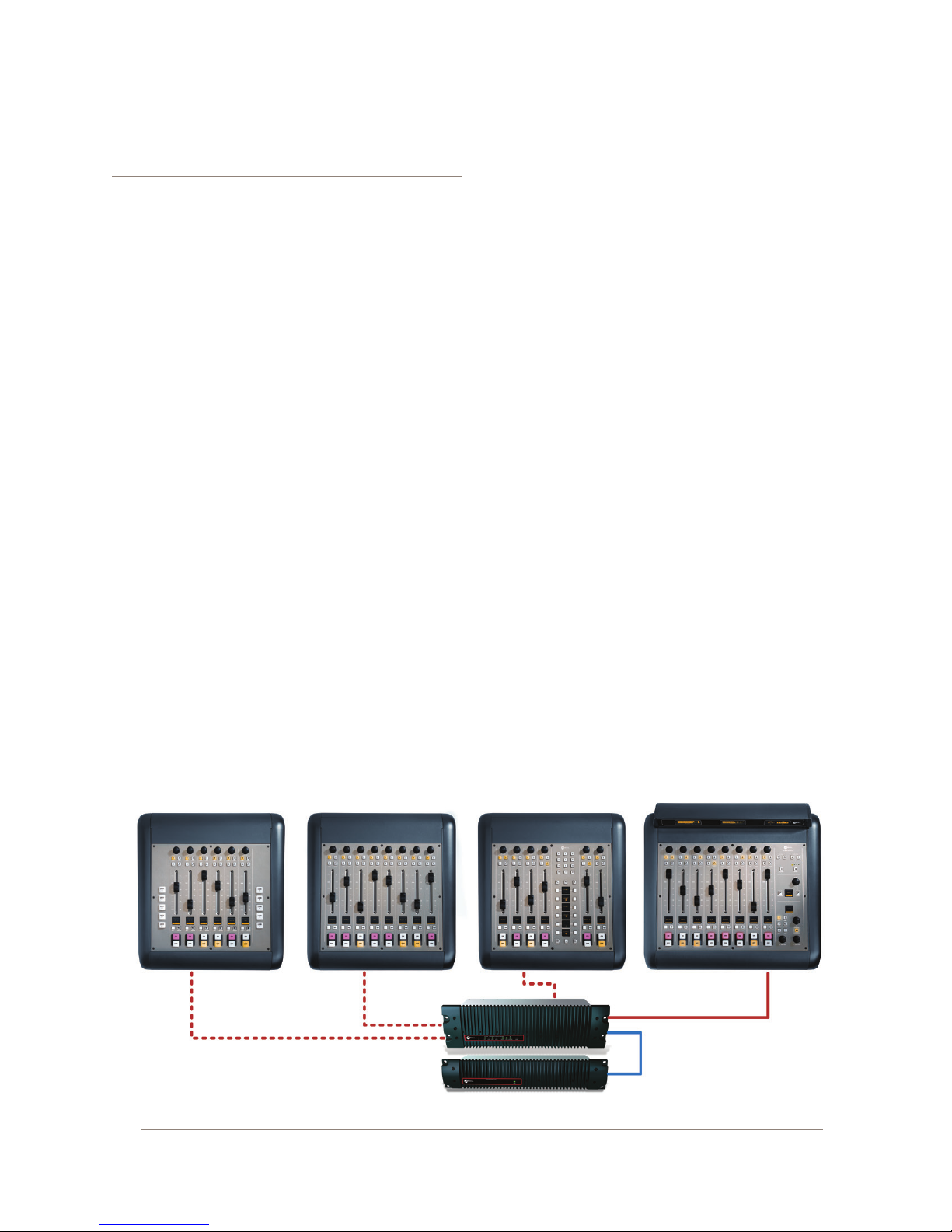
iQ Main Frame - Callouts and Operation . . . . . 22
System Settings . . . . . . . . . . . . . . . . . 27
iQ 8-Fader Expansion Frame . . . . . . . . . . . 27
iQ 6-Fader+Telco Expansion Frame . . . . . . . 27
iQ 6-Fader+User Keys Expansion Frame . . . . .29
Source-Specic Channel Controls. . . . . . . . . . .29
Control Room Operator Mic Channel . . . . . 29
Producer Microphone Channel . . . . . . . . . 29
Control Room Guest Microphone Channel . . . 29
Studio Microphone Channel . . . . . . . . . . 30
External Microphone Channel . . . . . . . . . 30
Phone Channel . . . . . . . . . . . . . . . . . 30
Codec Channel . . . . . . . . . . . . . . . . . 30
Remote Control . . . . . . . . . . . . . . . . . 31
Chapter Four: Show Proles . . . . . . . . . . . . . . 33
Creating A Show Prole. . . . . . . . . . . . . . . .33
Show Prole Options . . . . . . . . . . . . . . . . . 34
Chapter Five: Conguring GPIO . . . . . . . . . . . .39
GPIO Port Denitions . . . . . . . . . . . . . . . . .39
GPIO Operator’s Microphone Logic. . . . . . . .40
GPIO Control Room Guest Microphone Logic . . 41
GPIO Studio (Monitor 2) Guest Microphone Logic42
GPIO Producer’s Microphone Logic. . . . . . . .43
GPIO Line Input Logic . . . . . . . . . . . . . . .44

Introduction • vi
© 2014 Axia Audio - Rev 1.3.1
GPIO Codec Logic . . . . . . . . . . . . . . . . . 45
GPIO Telephone Hybrid Logic . . . . . . . . . . .46
GPIO Control Room Monitor Logic . . . . . . . . 47
GPIO Studio Monitor Logic . . . . . . . . . . . . 48
GPIO Computer Playback Device Logic. . . . . .49
GPIO Film Legendable User Button Module / Acces-
sory Panel / Rack Panel . . . . . . . . . . . . . . 50
GPIO Recording Device Logic . . . . . . . . . . .51
Assigning GPIO to a Source. . . . . . . . . . . . . .52
Connections to GPIO Ports . . . . . . . . . . . . . . 53
Input Connections . . . . . . . . . . . . . . . . . 53
Output Connections . . . . . . . . . . . . . . . . 54
Virtual GPIO . . . . . . . . . . . . . . . . . . . . 54
Conguring and using iQ User Keys . . . . . . . . . 55
Chapter Six: Advanced Controls . . . . . . . . . . . . 57
iQ Conguration Screens . . . . . . . . . . . . . . . 57
The iQ Control Center . . . . . . . . . . . . . . . 57
The Status Screen . . . . . . . . . . . . . . . . 57
The Setup Menu . . . . . . . . . . . . . . . . . 57
The Customize Menu . . . . . . . . . . . . . . 58
Log, Log History and Log Setup Menus . . . . 59
Brightness Control Menu . . . . . . . . . . . . 60
User Modules Menu. . . . . . . . . . . . . . .60
GPIO Conguration Menu . . . . . . . . . . . 60
Remote. . . . . . . . . . . . . . . . . . . . . .60
Prole Manager Menu . . . . . . . . . . . . . 61
IO Manager Menu. . . . . . . . . . . . . . . .61
Ethernet Switch settings (Precongured) . . . . 61
Chapter Seven: Networking with iQ . . . . . . . . . . 63
Inputs . . . . . . . . . . . . . . . . . . . . . . . . . 63
Outputs . . . . . . . . . . . . . . . . . . . . . . . . 64
GPIO. . . . . . . . . . . . . . . . . . . . . . . . . .65
Networking . . . . . . . . . . . . . . . . . . . . . . 65
Appendix A: iQ Specications . . . . . . . . . . . . . 67
Table of Inputs and Outputs . . . . . . . . . . . . . 68
Appendix B: iQ Block Diagrams . . . . . . . . . . . . 73
Appendix C: Channel / IP Worksheets . . . . . . . . . 81
Warranty . . . . . . . . . . . . . . . . . . . . . . . . . 85

Introduction • vii
© 2014 Axia Audio - Rev 1.3.1
A Note From The Vice President of Axia
2013 marks a banner year for Axia — this year
marks the rst decade of the Connected Studio.
In retrospect, it’s hard to believe it’s been 10 years
since a start-up division of Telos grabbed everyone’s
attention with a radical idea about building radio stu-
dios using Ethernet. At a time when “state of the art”
meant discrete digital audio, and a routing switcher
was something only the richest stations could af-
ford, Axia shocked everyone with the idea that studio
peripherals from the console to the audio processor
could be networked, and that everyone could have the
benets of a routing switcher — for about a third of
the cost of traditional technology.
When we launched Axia, Telos founder Steve
Church made a prediction. “Three things will hap-
pen,” Steve told us. “First, people will say that ‘it will
never work.’ When they’re proven wrong, they’ll say
‘It works, but you don’t need that.’ And nally, as they
see Axia becoming successful, they’ll say ‘IP-Audio?
We do that too!’”
Steve, as always, was right on the money. In 10
years, Axia Livewire has become the world’s most
popular IP-Audio networking technology, and our
mixing consoles are the world’s best-selling — they’re
on-air in over 4,000 studios, and counting. You’ll nd
Axia equipment everywhere: at privately-owned sta-
tions, and large clusters run by big conglomerates. At
established public broadcasters, and at newly-licensed
International stations. At government broadcast facili-
ties, and podcast studios. Needless to say, we’re hum-
bled by the trust broadcasters place in us — and by
your enthusiasm!
Being rst with new technology is nice, but we’ve
never been content to rest on our laurels. So the Telos
R&D team continues to innovate and expand the scope
of IP-Audio. Axia consoles are the rst and only IP-
Audio consoles with a pre-congured network switch
built in, to save broadcasters the effort and expense
of procuring and programming third-party switches.
Our compact xNode AoIP interfaces feature one-but-
ton setup, and can run on mains power or Power over
Ethernet (PoE) for exibility and redundancy. We’ve
even developed our own zero-conguration Ethernet
switch for Livewire – xSwitch – to make deploying
IP-Audio easier than ever.
More than 45 Livewire partners believe in the vi-
sion of the Connected Studio too. Collectively, they
make dozens of hardware and software products
(ranging from telephone systems to audio processors
to program automation) that interoperate directly with
Axia networks via Ethernet – making the connec-
tions “smart”, and eliminating the need to purchase
audio conversion devices. We’ve also partnered with
the high-performance audio standard RAVENNA to
expand broadcasters’ networking options even further.
And there are a lot more great new ideas in the cooker
— so watch this space!
In the nal analysis, Axia’s success isn’t due to
our efforts. It’s you, the broadcast professional, who
has embraced our vision, used our technology in ways
we never dreamed of, and raved about Axia products
to everyone who’d listen. We owe you a huge debt of
thanks. And we promise to never stop trying to amaze
and delight you.
So here’s to the next 10 years.
Onward and upward!
Marty Sacks
Vice President, Axia Audio

Introduction • viii
© 2014 Axia Audio - Rev 1.3.1
CAT.6, m n ig
n n dt r rt.
Wh ag s ts?.

Getting Started • 1
© 2014 Axia Audio - Rev 1.3.1
Getting Started
The following chapters of this manual will give you
an in-depth understanding of the capabilities of your
new iQ fader frames and QOR.32, from installation to
advanced functions. This section will help you get ev-
erything connected quickly, and point you to the parts
of the manual you’ll need to get up and running with a
minimum of fuss.
The Axia iQ family consists of these components:
• iQ Main Frame: 8-fader frame with master con-
trols and meters.
• iQ 8-Fader Frame: 8-fader expansion frame
• iQ 6-Fader+User Keys: Optional expansion
frame includes 6 faders and two banks of pro-
grammable user keys.
• iQ 6-Fader+Telco: Optional expansion frame
includes 6 faders and a Telos-style dual channel
hybrid controller.
• QOR.32: Rack-mounted CPU chassis with au-
dio I/O and GPIO connectors.
• QOR Backup Power Supply: Optional rack-
mounted backup power supply.
Making Connections
You’ve probably unpacked your boxes and are sitting
next to a pile of Axia gear, wondering what to do rst.
Here’s what you need to know in order to get started:
1. Packed with each of your iQ Frames is a cable
with 6-pin Molex™ connectors on each end. This is
the power/communications cable. Connect the end of
the cable without the strain relief to the correspond-
ing port on the iQ Frame connection panel. Connect
the other end of the cable to one of the connectors
labeled CONSOLE on the back of your QOR.32 unit.
You can use a maximum of three iQ Frames with
each QOR.32. One must be an iQ Main Frame.
2. Connect all iQ audio sources (microphones,
CD players, etc) to inputs of your QOR.32.
3. Connect monitor ampliers, headphone ampli-
ers, etc to outputs of your QOR.32. Be sure to set all
ampliers to their minimum volume setting.
4. Follow the instructions found in Chapter 1 to
congure IP address settings for the QOR.32.
5. Refer to the User’s Manuals packed with any
other Axia Audio Nodes for information on how to
congure IP addresses for these units.
What’s Next?
When you’ve completed physically connecting your
Axia hardware, jump to Chapter 2 for a quick tutorial
on conguring audio sources. With that done, you’ll be
a hop, skip, jump away from being on-air! After that,
you’ll likely want to do some in-depth reading about all
The iQ Family: (top L-R) iQ 6-Fader, iQ 8-Fader, iQ Phone, iQ Main Frame, (bottom) QOR.32 and QOR Backup PSU

Getting Started • 2
© 2014 Axia Audio - Rev 1.3.1
your new iQ can do. Here’s a brief description of the con-
tents of the following chapters:
• Chapter 1: iQ Frames and QOR.32 explains con-
nections and basic iQ setup.
• Chapter 2: iQ Inputs and Outputs explains how to
generate Source Proles and construct backfeeds for
selected sources.
• Chapter 3: iQ Operations takes you behind the
scenes to explore operator controls and options.
• Chapter 4:Show Proles illustrates how to set and
save unique “snapshots” tailored for specic shows.
These Show Proles can be instantly recalled when-
ever needed.
• Chapter 5: GPIO tells how to associate routable
logic commands with any audio source.
• Chapter 6: Advanced iQ Controls discusses ad-
vanced features that are congured in the iQ con-
guration web pages.
• Chapter 7: Livewire Networking and iQ will tell
you how to connect your iQ to a network and reap the
benets of networked studio systems.
• Appendices provide additional technical specica-
tions and a complete set of block diagrams for your
reference.
Read on. Enjoy your iQ.
Stay up to date! We recommend joining the
Axia Tech mailing list to ensure that you receive
immediate updates regarding new software or
documentation releases. You can do this by
clicking the “Sign Up Here” link at the top of
AxiaAudio.com/manuals/ & AxiaAudio.com/downloads/.

1: Setup and Connections • 3
© 2014 Axia Audio - Rev 1.3.1
Chapter One:
Setup and Connections
Introduction
If you are reading this manual, you are probably the
proud owner of a new iQ console. You’ve read the Get-
ting Started section, are probably already passing audio,
and are hungry for more knowledge. Here we go!
The Basics
iQ was designed to get you on the air as quickly as
possible with the least amount of effort. It’s the perfect
standalone radio console (and it even networks, too - see
Chapter 7: Livewire Networking and iQ for details on
how to do that).
This chapter covers connecting iQ to your other stu-
dio gear, such as microphones, CD players and other au-
dio playback devices. The audio outputs of the QOR.32
connect to control room monitors, preview (cue) speak-
er, headphones ampliers and audio recording devices.
These external audio devices may be analog or AES de-
vices.
The GPIO (General Purpose Input Output) ports pro-
vide logic control interfaces to devices such as air lights,
recorders and CD players.
The 100 Mbps Ethernet ports may be used to con-
nect PCs running Axia’s IP-Audio driver, to expand your
system by adding other Livewire devices such as Axia
Audio Nodes, or equipment from Axia Partners (see
AxiaAudio.com/partners/ for the latest list of companies
whose equipment connects directly to Axia networks).
1000 Mbps (Gigabit) Ethernet ports are used to con-
nect to other QOR.32 units or an Ethernet core switch
— another topic covered in Chapter 7.
6-pin Molex connectors are used to connect your iQ
Main, iQ Frames (max of 3 including Main) and CAN-
Bus accessory panels. A single cable from each Frame
will be used to connect it to the QOR.32. Each iQ Frame
must have a dedicated Console port. Accessory modules
can be daisy-chained from the CANBus Accessory port.
The D-sub combo connector connects ONLY to your
optional QOR Backup power supply. The IEC receptacle
is for your A.C. mains power connection.
Assigning an IP Address
Before you can congure your iQ hardware, you’ll
need to assign it an IP address. Press-and-hold the Meter
and Clock keys for three seconds. The Studio display
now shows the options and the Studio Monitor control is
used to navigate, select IP Address options and change
parameter values. Consult your network administrator if
you are unsure about what address to use.
Each iQ system requires a single, xed IP address.
The iQ Frames are controllers for the QOR.32 engine
and they share the same IP addresses. If the iQ is stand-
alone, the default IP address will probably be ne. See
Chapter 7 for more details when multiple iQ’s are used
or when your iQ is a part of a larger network.
Notes on Physical Installation
The QOR.32 is fan-free, so it can be located in any
studio without fear of unwanted noise. Those vents and
heat sinks serve a very important purpose! Be sure to
mount the QOR in an equipment rack with free air ow.
We recommend using a ventilated 1RU rack spacer
above and below the QOR.32 to ensure adequate ven-
tilation.
To install the iQ Frames in your studio, all you need
is a desk — no console cutout required. You may also
rack-mount your iQ Main Frame using the included
rack-mount hardware. This same hardware serves dou-
ble duty to join your iQ Frames together if you prefer
one, continuous console rather than individual units.
To join iQ console sections:
Remove the adjacent side bezels of the iQ Frames
that you wish to join and attach both rack-mount anges
to one of the frames as illustrated on the next page.

1: Setup and Connections • 4
© 2014 Axia Audio - Rev 1.3.1
Flip the iQ frames over and use the rack-mount
screws to securely attach the rack-mount anges to the
underside of the iQ Frames.
The physical arrangement of the frames is complete-
ly arbitrary. The channel assignments are determined by
the iQ Main port to which you connect each iQ frame.
QOR.32: Front Panel
The indicator panel of the QOR.32, shown on the
following page, is very simple. There are no controls
for you to push or turn. Conguration and setup is per-
formed from the console itself or through the iQ web
browser interface.
Front Panel Indicators
Even though there are no knobs or dials, the front
panel has some very useful indicators that tell you about
the health and status of your QOR.32. In all cases, solid
GREEN indicates normal operating conditions.
CHECK
This is a general health indicator for the QOR.32. If
this indicator is RED, immediately check the web pages
for abnormal operating conditions such as excessive
CPU temperature. Do not ignore this indicator. Note that
it is normal for this indicator to ash during boot-up.
LIVEWIRE
When lit, indicates that Livewire channels are being
taken from the network. If no network sources are being
received, this indicator is not illuminated.
SYNC
If your iQ is part of a larger network, a solid GREEN
indicates the QOR.32 is synchronized as a slave to the
Livewire network and that its internal clock is locked.
Flashing GREEN indicates that sync packets are being
received, but that iQ is not yet locked. It is normal for the
SYNC indicator to ash for several seconds at startup. If
it does not “lock” with a solid, non-ashing LED, this
may indicate an incorrectly congured network switch.
Check your Ethernet switch conguration or call Axia
24/7 Support for assistance.
MASTER
Solid GREEN indicates the QOR.32 is synchronized
as a Master clock to the Livewire network. This indi-
cator will always be green for a standalone console. If
you have any other Livewire devices, they should be re-
porting Sync or Slave. There should be only one Master
clock device in a Livewire network at any given time.

1: Setup and Connections • 5
© 2014 Axia Audio - Rev 1.3.1
Figure 1-1 shows both Master and Sync illuminated for
illustration purposes only.
Note: The MASTER and SYNC indicators are not
normally ON at the same time since the QOR.32
will be either a Master or Slave. This principle
applies to all Axia Livewire devices. Any Livewire
network will have only a single Master.
NET 1 and NET 2
These indicators provide the status of the two 1000
Mbsec (Gigabit) NICs in the QOR.32. Note that the unit
can be used with either or both ports connected to prop-
erly congured Ethernet switches or other QOR.32 units.
When the Gig1 or Gig2 ports have active connec-
tions, the NET1 or NET2 lamps (respectively) will illu-
minate. If a network cable is connected to a Gig port and
the corresponding NET lamp is unlit, a problem with the
network connection is indicated.
When a disconnected Ethernet link has been re-estab-
lished, the NET LED will blink with a 50% duty cycle
for about 5 seconds as the network activity is resumed.
Please consult Axia’s Ethernet switch conguration
guides for details when using Core switches in a larger
network. Ethernet Switch guides may be found on our
web site at AxiaAudio.com/manuals/.
PSU
There are two PSU indicators providing assurance
that the QOR.32 power supply rails are normal. Solid
GREEN indicates normal power supply status.
The PSU2 indicator is active only when am QOR
Backup is present and when the iQ console is congured
to incorporate the QOR Backup.
IP
This indicator will illuminate upon detection of an
external Ethernet core switch connected to the QOR.
QOR.32: Rear Panel
Power
• AC Mains: There is one standard IEC receptacle for
your mains power for voltages in the range from 100
to 240 VAC at either 50 or 60 Hz.
• PSU2 (Backup): This is a D-sub combo connector
for use only with the QOR Backup 48 VDC power
supply. Connect your optional backup power supply
with the provided cable.
Figure 1-1: QOR.32 - Front Panel

1: Setup and Connections • 6
© 2014 Axia Audio - Rev 1.3.1
Audio Connections
The QOR.32’s rear panel contains all of the connec-
tors used for audio I/O, Ethernet, GPIO, power supply
and the connections to your iQ frames. Note that we use
RJ-45 connectors for three purposes:
• Analog audio inputs and outputs
• AES audio inputs and outputs
• Ethernet (some with PoE - Power over Ethernet)
It is important to follow the proper conventions for
wiring these connectors and ensure that the connector
functions are not confused as damage may result if you
plug a network cable into an audio input.
Analog and AES Audio
The connector pin functions shown in Figure 1-3 are
the same for both the AES and Analog inputs and out-
puts.
The nominal audio level for analog line inputs and
outputs is +4 dBm. This audio level will provide you
with 20 dB of headroom.
Note: The well-labelled RJ-45 connectors on
the QOR.32 rear panel are used for different
functions. Be sure to use them only for their in-
tended purpose as described in this section.
Microphone Inputs
There are four XLR-F connectors on the rear panel
for connection of microphone inputs. These connectors
use the standard wiring convention for 3-pin XLR audio
connectors. These connectors may have 48-volt Phan-
tom power enabled via the QOR.32’s web page congu-
ration. Please take appropriate precautions if you con-
nect anything other than a microphone to these inputs
when Phantom power is enabled.
Figure 1-2: QOR.32 - Rear Panel Connections
Figure 1-3: RJ-45 Audio Connector Pinouts

1: Setup and Connections • 7
© 2014 Axia Audio - Rev 1.3.1
GPIO Connections
The QOR.32 includes eight GPIO ports, with pinouts
in the same conguration as the GPIO ports on other
Axia products. Please refer to Chapter 5: Conguring
GPIO for the functions of these ports and wiring dia-
grams for their DB-15 connectors.
Figure 1-4: GPIO Connector Pin-Outs
In most cases, a GPIO port will be associated with
a single source such as a CD player, studio microphone,
profanity delay, et cetera.
Optional PathnderPC software may also be used to
monitor and control GPIO for advanced applications.
The interconnections to GPIO ports will vary de-
pending on the type external equipment being used and
whether or not voltage is supplied by an external device.
Chapter 5: Conguring GPIO provides these details.
Ethernet Connections
The QOR.32 has three types of Ethernet connections
and it is important to use them as intended since the in-
ternal Ethernet switch is congured in a specic manner.
The types of connectors available are:
• 100 Mbps PoE (Power-over-Ethernet) ports designed
to be used with future Livewire accessories that will
obtain their power directly from their Ethernet con-
nections. These ports may also be safely used with
standard, non-PoE devices.
• 100 Mbps Ethernet standard ports are used to con-
nect PCs or other Livewire devices to your Livewire
network. These devices might include additional
Livewire nodes or PCs running the Axia IP-Audio
driver.
• Two 1000 Mbps (Gigabit) ports are used for connec-
tions to other QOR.32 units, or, in larger networks,
for connections to an Ethernet Core switch. Note
that these two ports are used as trunks and are not
intended for connection to Livewire source devices
such as Audio Nodes.
iQ Frame and CANBus Connections
iQ frames need only a single data / power connection
to operate. The QOR.32 includes four power/CANBus
connections for use in conjunction with your iQ control
surface. The accessory CANBus port is an additional
port that is available for future use.
Important: Like any electronic device, iQ can
be affected by static electricity. Use of a per-
sonal grounding device is strongly recommend-
ed while handling the unit during installation.
Your iQ surface must be connected to a grounded
metal permanent wiring system or other equipment
grounding conductor using the grounding lug located on
the console chassis. For ground sources, we recommend,
in order of preference:
• “Station Ground,” the heavy copper strap found in the
walls and oors of many radio studios.
• AC Safety Ground — the “3rd prong” of a nearby
outlet.
• A bonded electrical conduit.
#12 AWG GREEN stranded wire is the minimum
wire gauge acceptable for grounding the iQ mixer.
Important: Grounding reduces the risk of elec-
tric shock by providing a “path of least resis-
tance” for electric current. Improper grounding
can result in a risk of electric shock.
Check with a qualied electrician if you are in
doubt about how to properly ground this equip-
ment. If your local electrical code prohibits the
use of a Station Ground for this purpose, as de-
scribed above, use the specic “Safety Ground”
your local regulations mandate.
Console 1, 2, 3
There are three 6-pin Molex connector that are used
to provide DC power (48 vdc) plus CANBus data to your
iQ control surfaces.

1: Setup and Connections • 8
© 2014 Axia Audio - Rev 1.3.1
iQ frames must each be connected to a CONSOLE
port on the QOR.32 using only the supplied 6-conduc-
tor cables. Each frame has a discrete connection to the
QOR.32 A maximum of three fader frames (one Main
plus two others of any type) can be connected to a
QOR.32.
Note: Does it matter what Core port I connect
a console frame to? Fader channel numbers
are dependent on the QOR.32 console port to
which you connect the fader frames. The Con-
sole 1 port will assign the lowest channel num-
bers. Console 2 and Console 3 will assign higher
fader channel numbers. This scheme permits
you to arrange your fader frames in any desired
conguration and automatically assign channel
numbers to your faders.
One end of each iQ power/communication cable is
tted with a strain relief. Connect this end to the Molex
connector on the back of the QOR.32. Connect the other
smaller connector to the
Molex socket on each iQ Frame.
Each Frame must have a dedicated power/communica-
tion cable.
Since the CANBus connection cables include power
as well as data, there is a length restriction of approxi-
mately 50 feet. If you require longer cables than those
supplied with your iQ Frames, please contact your Axia
representative.
Accessory
The fourth 6-pin Molex connector on the rear panel
of the QOR.32 is labelled ACCESSORY. This is the
CANBus port that can be used to distribute data and 48
VDC to CANBus switch modules and accessory panels.
Several accessory modules can be connected in a daisy-
chain conguration with a termination on the last ac-
cessory panel. An Axia CANBus adaptor is available to
convert the Molex CANBus connector to the RJ-45 type
connector used on the Axia Accessory panels. This adap-
tor will simplify wiring of your CANBus accessories.
What is CANBus? Controller Area Network
(CAN) is a multicast shared serial bus standard,
originally developed in the 1980s by Robert
Bosch GmbH, for connecting electronic control
units (ECUs). Although initially created for auto-
motive purposes, nowadays it is used in many
embedded control applications.
The CAN data link layer protocol is standardized
in ISO 11898-1 (2003).
IP Address Conguration
To access System Settings from the iQ console,
press-and-hold the Meter and Clock key for three sec-
onds. The Studio display now shows the options and the
Studio Monitor control is used to navigate, select options
and change parameter values. Options available are:
• IP Address
• Subnet Mask
• Gateway
• Save and Reboot
To exit, select EXIT and press the Studio Monitor
control.
Note: After making changes to any QOR.32 IP
address settings, you must reboot the unit for
these changes to take effect.
“Gateway” settings on a QOR.32 are not usually re-
quired; however, a valid gateway enables access to the
iQ conguration remotely, from outside your network. A
gateway also facilitates the use of an external NTP serv-
er. Enter the IP address of your master router (the one
with external network connections) whenever you’re
given the option to enter a gateway address.
Note: If your system employs an Ethernet core
switch, the Ethernet core switch must have an
IP address that is lower than any of your iQ units
or Ethernet edge switches. This function of the
IGMP standard ensures that the multicast que-
rier is handled by the core switch if one exists.
The querier will be passed off transparently to
another switch should the core switch fail or be
disconnected.
Figure 1-5: Detail of data/communication cable ends.

1: Setup and Connections • 9
© 2014 Axia Audio - Rev 1.3.1
Console Conguration
Now that your iQ has an IP address and you have
a fader frame or two connected, you will need to tell
the QOR.32 what is plugged to its CANBus slots so that
fader numbers can be assigned. You will need to provide
your computer with a static IP address that is in the same
network as the iQ. For example, if you gave the iQ an
IP address of 192.168.2.40, a good IP address for your
computer could be 192.168.2.45.
Once your computer is congured, enter your iQ’s IP
address into your PC’s browser, and when the iQ Con-
trol Center appears, choose Console Cong from the
iQ main menu. When you connect to the iQ, you will be
prompted for a user name and password. By default, the
user name is “user” and there is no password.
In the example shown in Figure 1-6, we have a Main
Frame connected to Console Port 1 and a Phone Frame
connected to Console Port 3. In this conguration, the
faders on the Main Frame will be assigned channels 1
through 8 and the faders on the Phone Frame will be as-
signed channels 9 through 14.
What’s Next?
Take a break! You’re done with initial set-up. When
you’re ready, continue to Chapter 2: iQ Inputs and Out-
puts to walk through the software conguration of the
Inputs and Outputs on your iQ.
Figure 1-6: QOR Control Center

1: Setup and Connections • 10
© 2014 Axia Audio - Rev 1.3.1
Cng t pad us,
t m ldng —
t’ e. (N uc.)

2: Inputs and Outputs • 11
© 2014 Axia Audio - Rev 1.3.1
Chapter Two:
Inputs and Outputs
In this chapter we’ll discuss how to congure the in-
puts and outputs for your iQ system by using your com-
puter’s web browser. While browsing this chapter you
may nd useful the iQ block diagrams in Appendix B.
iQ has a built-in Ethernet switch and Web server for
options conguration. To access it, all you need is a com-
puter connected to its Ethernet switch. Since Livewire IP
addresses are managed without DHCP, you will need to
ensure that your PC has a manually-assigned IP address
in the same subnet as the QOR.32. Contact your network
administrator if you are not sure how to set up a xed IP
address for your PC (but if you’re reading this, we think
you’ve probably got it covered yourself).
Note: Axia web interfaces have been tested with
Microsoft(TM) Internet Explorer, version 6 or lat-
er, but also work with other browsers.
Adobe(TM) Flash Player is used for some real-
time monitoring features but is not essential for
setup and conguration. If installed, your pop-
up blocker must be disabled. You may download
Adobe Flash Player at http://get.adobe.com/
a s h p l ay e r/.
Once your PC is properly connected to the Axia
Livewire network, direct your web browser to the IP ad-
dress of your iQ. When you connect to the iQ, you will
be prompted for a user name and password. By default,
the user name is “user” and there is no password.
First, we’ll walk through the Audio IO Manager to
congure your Inputs and Outputs. Then, we will illus-
trate how Source Proles and Show Proles are used
with your iQ system.
Inputs
Your QOR.32 has several connectors on the rear
panel that accommodate microphones, analog stereo
line and AES inputs. Chapter 1 discussed the details of
these physical connectors. Now, let’s look at the software
conguration of these inputs.
Figure 2-1: Audio IO Manager - Inputs
v
Figure 2-1 shows the web page conguration for In-
puts for your QOR.32. There are three types of inputs.
Microphone Inputs
The four XLR-type connectors on the rear panel are
intended to be used for mono microphone signals. Each
of those inputs has the following parameters:
• Phantom Power (48 vdc) is individually enabled
for each of the four microphone inputs by selecting
this check box.
• PreAmp Gain is adjustable to a maximum of 65 dB.
This setting will adjust the microphone level prior to
all other signal processing.
• Input Gain is adjustable from -64 to +24 dB. If you
are conservative with your PreAmp gain, you may
wish to apply a few dB of additional gain at this stage.
Analog Line Inputs
These sixteen inputs are for line-level stereo signals
connected to the analog line RJ-45 connectors on the
rear panel. They have only one adjustment.

2: Inputs and Outputs • 12
© 2014 Axia Audio - Rev 1.3.1
• Input gain allows you to specify a gain from -64 to
+24 dB.
AES/EBU Inputs
There are two AES/EBU digital inputs on RJ-45 con-
nectors. These digital inputs are equipped with sample
rate converters so a specic incoming sample rate or
AES clock is not required.
• Input gain allows you to specify a gain from -127.5
to 0 dB.
Be sure to click Apply after making changes in each
input section.
Now that the inputs have been tweaked for proper
system audio levels, we can manage that audio and auto-
matically associate logic with the different sources you
have connected to your iQ. We use a concept that we call
Proles to do this.
What’s a Profile?
A Prole is a group of parameters that are stored in
memory for instant recall. The use of Proles makes
the operation of your iQ quick and intuitive. In the iQ
console’s design, there are two types of proles: Source
Proles and Show Proles. Show Proles (discussed in
detail in Chapter 3) contain all of the “snapshot” settings
that would be associated with a console scene or preset.
This terminology is commonly used in the sound rein-
forcement or recording studio industries.
Show Proles
Our Show Proles keep track of monitor bus set-
tings, fader channel assignments, jock preferences, lock-
outs and many other parameters.
Source Proles allow you to control access and con-
gurations of the individual sources as they are used on
each iQ console in your facility. Source Prole param-
eters may include name, source type, backfeed prefer-
ences, associated logic and much more.
Source Proles
One of the most repetitive and tedious parts of studio
building has always been tying “data” to audio sources.
Consider the wiring of analog line selector modules: you
needed a cable for the remote audio source, a set of wires
for a “start” closure, another set for “stop” — even with
TDM routers, an operation as seemingly simple as logic-
follows-audio often turns out to be not so simple.
Mix-minus and IFB generation has also been a prob-
lem in the past. Too often it’s a complicated process that
requires air talent to correctly determine source and bus
assignments at a moment’s notice. How many times has
unwanted audio been aired thanks to this error-prone
procedure?
Your iQ eliminates these headaches by automatical-
ly merging audio, logic and program data into a single,
routable information stream. Since audio in a Livewire
network is transported as packetized data, it’s easy for
us to “piggyback” other data along with the audio. This
association is accomplished through the use of Source
Proles.
A Source Prole contains all of the parameters that
are unique to a specic audio input (source) as it applies
to a specic iQ console. Source Proles can assign mod-
iers to an audio input. Characteristics like Pan, Trim
and even Mix-Minus source selections can be set in the
Source Prole and automatically loaded whenever that
source is assigned to an iQ fader.
The result of all this is that iQ is always presented
with complete, consistent information about how you
want a given audio input (source) to be handled. Your
board operator will never have to worry about Mix-Mi-
nus again!
Source Conguration
The iQ web browser interface is used to congure
Sources. To get started:
• Open the web browser on your computer and point it
to the IP address you previously assigned to your iQ.
• You’ll be prompted to enter a user name and pass-
word. The default user name is “user”. Leave the
Other manuals for iQ
1
This manual suits for next models
2
Table of contents
Other Axia Music Mixer manuals