axing SAT-Navi User manual

SAT-Navi
SZU 21-00
EN – Read and keep
OPERATION INSTRUCTIONS

Operation Instructions
SZU 21-00
2
© AXING AG• Reserving change in design and type-We cannot be heldliable for printing errors 14.04.11
Safety Notes
Turn off the receiver or any used power supply before installing, to avoid short-
circuit.
Installation and repairs to the equipment may only be carried out by technicians
observing the current VDE guidelines. No liability will be assumed in the case of
faulty installation and commissioning.
Before opening the device, pull the mains cable or remove the power supply,
otherwise there is a danger to life. The same is true when you clean the device or
perform work on the connections.
Power feeding cables as well as feeder lines may not be damaged or clamped by
objects of any kind.
Avoid exposure of the equipment to direct sunlight and to other heat sources (e. g.
radiators. other electricaldevices, chimney, etc.). Absolutely avoid that cables come
near any source of heat (e.g. radioators,other electrical devices, chimney, etc.)..

Operation Instructions
SZU 21-00
14.04.11 © AXING AG • Reserving change in design and type - We cannot be held liable for printing errors
3
Content
1 Common 4
1.1 Delivery 4
1.2 Description 5
2 Power supply 7
2.1.1 External power supply 7
2.1.2 Satellite receiver 7
2.1.3 Internal batteries 7
3 Operation 8
3.1 Main menu 8
3.1.1 Short Circuit Protection 10
3.2 Light menu 10
3.3 Update menu 11
4 Technical specifications 14
4.1 List of tables 15
4.2 List of illustrations 15

Operation Instructions SZU 21-00
Chapter 1: Common
4
© AXING AG• Reserving change in design andtype -We cannot be held liable for printing errors 14.04.11
1Common
1.1 Delivery
Fig. 1: Delivery
SAT-Navi SZU 21-00
Transparent weather-protection
RS-232 Adapter
Note
Batteries (12xAA) are not included in delivery!
Separately available:
Programming-Set SZU 22-00, consisting of:
1 x AdapterRS-232 to USB
1 x USB connecting cable
1 x Null-Modemcable
1 x Driver CD ROM
Switching mode power supply SZU 99-22

Operation Instructions SZU 21-00
Chapter 1: Common
14.04.11 © AXING AG • Reserving change in design and type - We cannot be held liable for printing errors
5
1.2 Description
This product is simple and convenient for setting and aligning a satellite dish. Using the
satellite parameters the user can set and align a satellite dish quickly, accurately and
easily.
Fig. 2: Inputs, display, buttons
Inputs, display, buttons
1. DC-power supply socket
If the SAT-Navishould be operated with an external power supply (which is not
included) please connect it here.
2. Slideswitch
In the upper position, the SAT-Navi will acquire power from the external power
supply or from tuner power supply input (by a connected receiver). In the lower
position, the SAT-Navi will acquire the power supply from the AA cells in the battery
compartment.
3. Low Voltage LED
The red LED is glowing, when the input voltage is too low (< 13,3 V) or when the
batteries are empty.
4. Power LED
The LED is glowing, when the device is in operation.
LNB
Multiswitch
SAT-Receiver
ext. power
supply
DC-power
supply
socket

Operation Instructions SZU 21-00
Chapter 1: Common
6
© AXING AG• Reserving change in design andtype -We cannot be held liable for printing errors 14.04.11
5. Buttons (,, OK)
To navigate in the software menu
6. LC- Display
Shows menu and additional information.
7. LNB input
Satellite signal input port - connect directly to the LNB.
8. DC power supply input
The SAT-Navi can be supplied by a connected power supply (SZU 99-22) or
satellite receiver using this F-socket.
At the bottom side
Fig. 3: Battery compartment
9. Battery compartment
Here, you can insert 12 AA (Mignon) batteries or rechargeable batteries to power
the device independently of any power supply.
10. RS232 - serial port
Interface used for software updates. (Please see in “Update menu”)
You will find the port behind the battery flap.
9
10 7
8

Operation Instructions SZU 21-00
Chapter 2: Power supply
14.04.11 © AXING AG • Reserving change in design and type - We cannot be held liable for printing errors
7
2Power supply
There are three ways to establish the power supply of the device:
2.1.1 External power supply
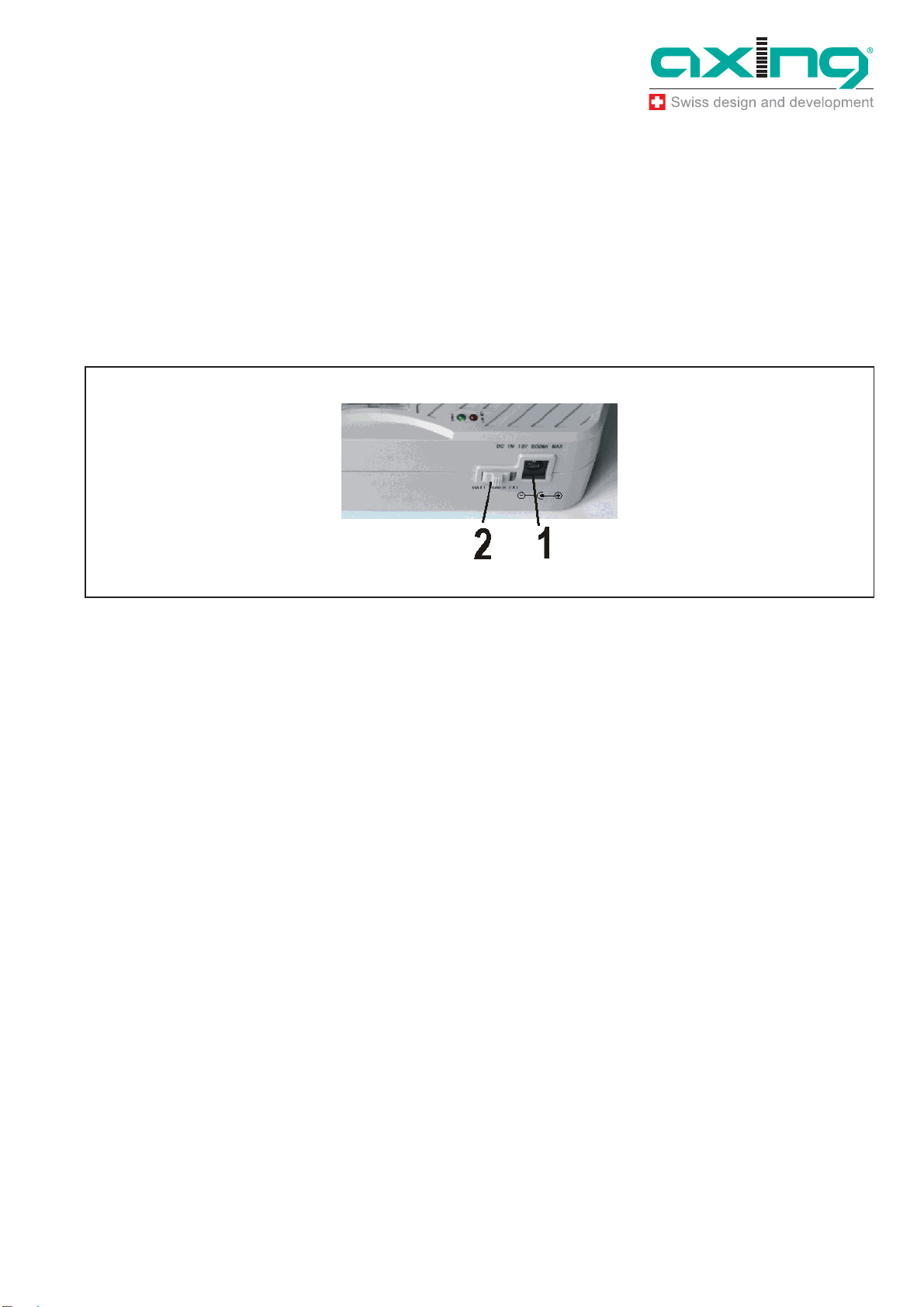
Connect the external power supply to the DC-power supply socket (1).
Make sure the slide switch (2) is in the position (“EXT”).
Fig. 4: DC-power supply socket (1),slide switch (2)
2.1.2 Satellite receiver
The SAT-Navi can be operated by delivering the power remotely from a satellite
receiver or multiswitch (which may be supposed to be connected to the LNB after
searching the Satellite).
The receiver/multiswitch should be able to deliver 600mA of current to the LNB!
Make sure the power supply selector is in the position (“EXT”).
Connect the LNB/IF input of the satellite receiver to the DC power supply input (8)
of theSAT-Navi
If the SAT-Navi does not power up or switches off when trying to search satellites,
the current delivered by the receiver may be insufficient. Please use another
receiver or another way of supply.
2.1.3 Internal batteries
Make sure, you have inserted fitting batteries into the compartment in the right
direction.
Put the Power Supply Selector in the lower position (“BATT”) to activate battery
operation.
You can use non-rechargeable and rechargeable batteries in AA size.

Operation Instructions SZU 21-00
Chapter 3: Operation
8
© AXING AG• Reserving change in design andtype -We cannot be held liable for printing errors 14.04.11
Low Voltage
If the voltage of any power source is lower than 13.3V, the red low voltage LED
lights up
Take care, thatthe inputvoltage is always higher than13.3V.
If you are using rechargeable batteries, switch off (to “EXT”) the device when the
red LED lights up to prevent the cells from total discharge.
3Operation
3.1 Main menu
At power on, the display shows version information of the software, and then appears
the main menu.
Fig. 5: Main menu
With the buttons /, you canchoose thefollowingoptions:
SAT-Navi(to align the satellite dish to a desired satellite)
Light (toggle the LCD background light)
Update (to initiate the software update by the USB Adapter)

Operation Instructions SZU 21-00
Chapter 3: Operation
14.04.11 © AXING AG • Reserving change in design and type - We cannot be held liable for printing errors
9
SAT-Navi menu
To align a satellite dish, please take the following steps:
1. Select asatellite fromthe list
Fig. 6: SAT-Nav menu
2. Choose if you want to search the satellite with the default transponder (FREQ.
DEFAULT) or with other transponders (FREQ. LIST). Please prefer (FREQ.
DEFAULT), because the identification of the satellite is more precise for this option.
Fig. 7: Transponder
ÎIf you choose (FREQ. LIST), you can select the transponder in the following menu .
Now, the Satellite and Transponder is chosen and the device tries to lock on a signal
from the desired satellite.
Fig. 8: Searching of a signal

Operation Instructions SZU 21-00
Chapter 3: Operation
10
© AXING AG• Reserving change in design andtype -We cannot be held liable for printing errors 14.04.11
3. Please move now the Satellite dish antenna slowly until you clearly hear the buzzer
noise. The SAT Navi has logged-in and reckognized the wanted Satellite. The
following other informations are displayed now too:
P: Signal Strength (in dBµV)
BER: Bit Error Rate
Q: Signal Quality (Bar Graph)
Fig. 9: Signal
With this Information and the acoustic signal, you can fine-tune the antenna to the
optimal position.
The frequency of the acoustic signal is linked tothe signal quality. So you can search
the satelliteand fine-tune the position also without seeing the display of the Sat
Navigator.
ÎTo exit the Satellite Navigator function, just press OK.
3.1.1 Short Circuit Protection
If there is a short circuit on the LNB input, the LNB powerwill be cut off and there will be
the message “Short c. detected” in the display.
After you have removed the cause for the short circuit, it appears the message “Short c.
restored”and the LNB Power isswitchedon again.
3.2 Light menu
In the Light Menu, you can switch the background light of the LCD on or off.

Operation Instructions SZU 21-00
Chapter 3: Operation
14.04.11 © AXING AG • Reserving change in design and type - We cannot be held liable for printing errors
11
3.3 Update menu
For always being up to date, there is a possibility to update the software of the Satellite
Navigator by aserial (RS-232) interface. Since most modern PCs don’t have a RS-232
port any more,an adapter to USBhas tobe used.
To update the software, please do the following steps:
1. Connect the update adapter to the Satellite Navigator at the connector found in the
battery compartment (see picture)..
Fig. 10: RS-232-Adapter
2. Connect the update adapter to the USB adapter with the connection cable.
RS-232-
A
dapter

Operation Instructions SZU 21-00
Chapter 3: Operation
12
© AXING AG• Reserving change in design andtype -We cannot be held liable for printing errors 14.04.11
Fig. 11: Null modem cable and USB adapter
3. Connect the USB adapter to your PC.
4. Start the software update application on your PC and choose the right COM-Port.
If you are not sure, which COM-Port to choose, under Windows you can findout the
right port in the device manager.
5. Press “Send” on the update tool.
6. Power on the Satellite Navigator and choose “Update” from the main menu.
The Satellite Navigator begins to download, this willtakes some minutes. After the
update, the software is burned into the internal flash memory.
DO NOT SWITCH OFF WHILE THE SOFTWARE IS BURNING!
If the update was not successful, there might bethe following reasons:
1. The communication between the Satellite Navigator and the update application
failed.
Fig. 12: Time out
Îplease check the connections and make sure you have selected the right COM port.
2. You try to update with the same version, which is already on the device.

Operation Instructions SZU 21-00
Chapter 3: Operation
14.04.11 © AXING AG • Reserving change in design and type - We cannot be held liable for printing errors
13
Fig. 13: Update cancelled
There will also be the message “The STB is up to date!” in that case.

Operation Instructions SZU 21-00
Chapter 4: Technical specifications
14
© AXING AG• Reserving change in design andtype -We cannot be held liable for printing errors 14.04.11
4Technical specifications
Frequency range 950…2150MHz
RF connecters F female
Operating voltage 13...19 VDC
Current consumption 300mA
Tab. 1: Data sheet

Operation Instructions SZU 21-00
Chapter 4: Technical specifications
14.04.11 © AXING AG • Reserving change in design and type - We cannot be held liable for printing errors
15
4.1 List of tables
Tab. 1: Data sheet 14
4.2 List of illustrations
Fig. 1: Delivery 4
Fig. 2: Inputs, display, buttons 5
Fig. 3: Battery compartment 6
Fig. 4: DC-power supply socket (1),slide switch (2) 7
Fig. 5: Main menu 8
Fig. 6: SAT-Nav menu 9
Fig. 7: Transponder 9
Fig. 8: Searching of a signal 9
Fig. 9: Signal 10
Fig. 10: RS-232-Adapter 11
Fig. 11: Null modem cable and USB adapter 12
Fig. 12: Time out 12
Fig. 13: Update cancelled 13

Operation Instructions SZU 21-00
Chapter 4: Technical specifications
16
© AXING AG• Reserving change in design andtype -We cannot be held liable for printing errors 14.04.11
This manual suits for next models
1
Table of contents