axing MIE 3-02 User manual

Hersteller
AXING AG
Gewerbehaus Moskau
8262 Ramsen
EWR-Kontaktadresse
Bechler GmbH
Am Rebberg 44
78239 Rielasingen
Stand 2019-12-15
Technische Verbesserungen, Änderungen im Design, Druckfehler und Irrtümer
vorbehalten.
MIE 3-02 | MIE 6-02
MIE 3-02/48 | MIE 6-02/48
premium-line
IP zu DVB-T2
8Kext | 49,8 Mbps
Quickstart-Anleitung
Technische Daten:
Sicherheitshinweise:
Die Installation des Gerätes und Reparaturen am Gerät sind auss-
chließlich vom Fachmann unter Beachtung der geltenden VDE-Richtlinien
durchzuführen. Bei nicht fachgerechter Installation und Inbetriebnahme wird
keine Haftung übernommen.
Das Gerät niemals öffnen. Es befinden sich keine vom Benutzer zu wartende
Teile im Geräteinnern, jedoch tödliche Spannungen. Dies gilt auch, wenn Sie
das Gerät reinigen oder an den Anschlüssen arbeiten.
Verwenden Sie ausschließlich das dem Gerät beiliegende Netzkabel. Es
dürfen am Netzkabel auf keinen Fall Teile ausgetauscht oder Veränderungen
vorgenommen werden. Es besteht sonst Lebensgefahr.
Wenn Sie beabsichtigen das Gerät für längere Zeit nicht zu verwenden, emp-
fehlen wir Ihnen aus Sicherheitsgründen sowie zur Energieeinsparung das
Gerät vollständig vom Netz zu trennen, indem Sie den Netzstecker ziehen.
Lassen Sie das Gerät vor der Inbetriebnahme der Raumtemperatur an-
gleichen, insbesondere wenn das Gerät betaut oder starken Temperatur-
schwankungen ausgesetzt war.
Das Gerät darf nur in gemäßigtem Klima betrieben werden.
Das Gerät darf nur in trockenen Räumen betrieben werden. In feuchten
Räumen oder im Freien besteht die Gefahr von Kurzschlüssen (Achtung:
Brandgefahr) oder elektrischen Schlägen (Achtung: Lebensgefahr).
Das Gerät darf keinem Tropf- oder Spritzwasser ausgesetzt werden. Es dürfen
keine mit Flüssigkeiten gefüllten Gegenstände wie Vasen auf das Gerät
gestellt werden
Planen Sie den Montage- bzw. Aufstellort so, dass Sie in Gefahrensituationen
den Netzstecker leicht erreichen und den Stromkreis unterbrechen können.
Wählen Sie den Montage- bzw.Aufstellort so, dass Kinder nicht unbeauf-
sichtigt am Gerät und dessen Anschlüssen spielen können. Der Montage-
bzw. Aufstellort muss eine sichere Verlegung aller angeschlossenen Kabel
ermöglichen. Stromversorgungskabel sowie Zuführungskabel dürfen nicht
durch irgendwelche Gegenstände beschädigt oder gequetscht werden.
Das Gerät nur auf ebenem, festen Untergrund betreiben und gegen unbeab-
sichtigte Bewegungen entsprechend sichern.
Setzen Sie das Gerät niemals direkter Sonneneinstrahlung aus und ver-
meiden Sie die direkte Nähe von Wärmequellen (z. B. Heizkörper, andere
Elektrogeräte, Kamin etc.) Bei Geräten, die Kühlkörper oder Lüftungsschlitze
haben, muss daher unbedingt darauf geachtet werden, dass diese keinesfalls
abgedeckt oder verbaut werden.
Sorgen Sie für eine großzügig bemessene Luftzirkulation um das Gerät.
Damit verhindern Sie mögliche Schäden am Gerät sowie Brandgefahr durch
Überhitzung. Bei 19-Zoll-Rack-Montage muss mindestens ein Freiraum von 5
cm vor und hinter dem Gerät gegeben sein.
Achten Sie unbedingt darauf, dass Kabel nicht in die Nähe von Wärmequellen
(z.B. Heizkörper, andere Elektrogeräte, Kamin etc.) kommen.
Insbesondere ist die Gewährleistung und Haftung ausgeschlossen für die Fol-
gen fehlerhafter Benutzung, bei unsachgemäß vorgenommenen Änderungen
oder Instandsetzungsarbeiten durch den Kunden. Benutzen Sie das Gerät
ausschließlich wie in der Betriebsanleitung vorgegeben und insbesondere
nach dem Stande der Technik.
Das DVB-C/T-Verteilnetz muss gemäß EN 60728-11 aufgebaut und entsprech-
end geerdet werden.
Hinweis: Sie finden die vollständigen technischen Daten indem Sie auf www.axing.com
im Suchfeld den Artikel eingeben.
Hiermit erklärt die AXING AG, dass die gekennzeichneten Produkte den
geltetenden Richtlinien entsprechen.
WEEE Nr. DE26869279 | Elektrische und elektronische Komponenten nicht
mit dem Restmüll, sondern separat entsorgen.
Typ MIE 3-02 MIE 6-02
IPTV-Eingang
Unterstützte Transport-
streams SPTS, MPTS (CBR/VBR)
Max. Anzahl
(ausMPTSoderSPTS) 512 2×512
Unterstützte Protokolle IP V4; UDP; RTP; IGMP v2, v3
Gesamtnettodatenrate 1 × 900 Mbps 2 × 900 Mbps
Ausgang
Anzahl Kanäle 1 × 3 × DVB-T2 2 × 3 × DVB-T2
Frequenzbereich 109…862 MHz
Kanalbandbreite 7 MHz, 8 MHz
Mögliche Frequenzänderung -4…+4 MHz (0.5 MHz steps)
Anschluss 1 × F-Buchse 2 × F-Buchse
Messbuchse 1 × F-Buchse (–30 dB) 2 × F-Buchse (–30 dB)
Ausgangsmodulation
Konformität
EN 50083-9 | ETSI TS 101 154 | ETSI EN300 429 |
ETSIEN300 744
DVB-T2 acc. to EN 302 755, mode A (single PLP)
Typ QPSK, QAM16, QAM64, QAM256
Unterstützte Ausgangsformate MPEG-2/H.262, MPEG-4/H.264 and HEVC/H.265
MER ≥ 43 dB
BER ≥9x10⁻⁹
Schulterdämpfung ≥ 56 dB
C/N ≥45 dB
Reflexion >14 dB
Bitrate, max. 49,8 Mbps
FFT 1K, 2K, 4K, 8K, 8Kext mode
FEC 1/2, 3/5, 2/3, 3/4, 4/5, 5/6
Schutzintervall 1/4, 19/128, 1/8, 19/256, 1/16, 1/32, 1/128
Schnittstellen
IPTV-Eingang 1 x RJ45 2 x RJ45
CAS/IPTV (redundant) 1 x RJ45 2 x RJ45
Konformität IEEE 802.3, 1000 Base-T (GigE)
Konfiguration/CAS 1 × RJ-45 2 × RJ-45
Konformität IEEE 802.3, 10/100 Base-T
Allgemein
Betriebsspannung 100…240 VAC/50…60 Hz
48 VDC
Leistungsaufnahme 30 W 60 W
Betriebstemperaturbereich
(gemäßEN60065) –10°C…+50°C
Produktbeschreibung
MIE 3-02 Beinhaltet 1 Modul, unterstützt SPTS und MPTS (auch gemischt),
wandelt maximal 512 Eingangs-Streams in 3 x DVB-T2
Ausgangskanäle.
MIE 3-02 Beinhaltet 2 Module, unterstützt SPTS und MPTS (auch gemischt),
wandelt maximal 2×512 Eingangs-Streams in 2 x 3 DVB-T2-
Ausgangskanäle.
9MIE 3-02 und MIE 6-02 enthalten zwei Spannungsversorgungen
für100…240VAC.
9MIE 3-02/48 und MIE 6-02/48 enthalten zwei Spannungsversorgungen für
36…60 VDC.
Lieferumfang
1 × IP to DVB-T2
2 × Netzkabel
1 × Quickstart-Anleitung
Hinweis
Sie finden die vollständige Betriebsanleitung zum Download indem Sie auf
www.axing.com im Suchfeld den Artikel eingeben.
Montage und Anschluss
Vor Montage und Anschluss Netzstecker ziehen!
Montage im 19“-Rack
Es muss mindestens 5 cm Freiraum vor und hinter dem Gerät gegeben sein.
Schieben Sie das Gerät in das 19“ Rack.
Schrauben Sie das Gerät mit vier Schrauben fest.
Potentialausgleich
Gerät gemäß EN 60728-11 am Potentialausgleich anschließen.
Verwenden Sie den Potentialausgleichsanschluss am Gerät.
Um den Außenleiter der Koaxialkabel am Potentialausgleich anzuschließen,
verwenden Sie z. B.QEW Erdungswinkel oder CFA 7-01 Erdungsblöcke.
Spannungsversorgung 100…240VAC
Schließen sie beide Netzteile mit den beiliegenden Kabeln an
100…240VAC an.
Spannungsversorgung 36…60 VDCC
Die Anschlüsse für die Spannungsversorgung bestehen aus 2 × M4-Schrau-
ben.
Verbinden Sie die DC-Anschlüsse mit 36… 60 VDC.
Wichtig: Achten Sie auf die richtige Polung. Verwenden Sie ausreichende
Leiterquerschnitte.
IPTV-Eingang
Schließen Sie den IPTV-Eingang an einem Ethernet-Switch an, der mit der
IPTV-Quelle verbunden ist. Verwenden Sie dazu Class 5/6 Ethernet-Kabel
mit RJ-45-Steckern.
HF-Ausgang
Verbinden Sie den Ausgang (RF OUT) mit dem vorhandenen Verteilnetz.
Verwenden Sie hierfür ein hochgeschirmtes Koaxialkabel mit einem F
Anschlussstecker.
Konfiguration
Die Konfiguration der Geräte erfolgt über eine grafische Benutzeroberfläche.
Für den Zugriff auf die Benutzeroberfläche benötigen sie einen handelsübli-
chen PC/Laptop inklusive Netzwerkschnittstelle, handelsüblichem Netzwerk-
kabel und die aktuelle Version eines Webbrowsers.
Das MIE 3-02 enthält ein Modul A
Werks-IP-Adresse des Moduls A: 192.168.0.145
Subnetz-Maske: 255.255.255.0
Das MIE 6-02 enthält zwei Module A und B. Jedes Modul hat eine eigene
Konfigurationsschnittstelle und eine eigene IP-Adresse.
Werks-IP-Adresse des Moduls A: 192.168.0.145
Werks-IP-Adresse des Moduls B: 192.168.0.148
Subnetz-Maske: 255.255.255.0
Zugriff auf die Konfigurationsoberfläche:
Ändern Sie die IP-Adresse Ihres PC/Laptop z.B. auf 192.168.0.1, Sub-
netz-Maske 255.255.255.0.
Schließen Sie den PC am RJ-45-Ethernet-Anschluss Control an
Geben Sie jetzt die IP-Adresse des Moduls in den Web Browser ein.
Die Konfigurationsoberfläche ist mit einem Kennwort geschützt.
Geben Sie das werkseitig eingestellte Passwort Ramsen8262 ein (ändern
Sie das Passwort nach der ersten Inbetriebnahme).
Klicken Sie auf die Schaltfläche ENTER PASSWORD.
Die Startseite öffnet sich.
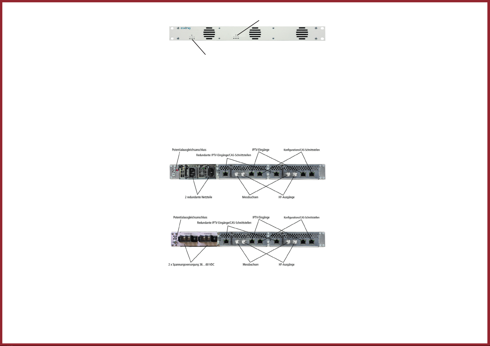
Anzeigeelemente
LEDs 1…3
des Moduls B (MIE 6-02)
LEDs 1…3
des Moduls A (MIE 3-02/6-02)
Die LEDs zeigen den Zustand der Ausgangsmodulatoren an:
9Wenn ein Modulator mit Programmen befüllt ist und der Modulator nicht
überlastet ist, leuchtet die entsprechende LED grün.
9Wenn ein Modulator eingeschaltet, aber nicht befüllt ist (ohne Inhalt),
blinkt die entsprechende LED.
9Wenn ein Modulator überlastet ist (zu viel Inhalt), leuchtet die LED rot.
9Wenn ein Modulator ausgeschaltet ist, ist die entsprechende LED aus
Anschlüsse
MIE 3-02 und MIE 6-02
MIE 3-02/48 und MIE 6-02/48
Upgrade des MIE 3-02:
Das MIE 3-02 kann um ein Modul MIM 3-02 erweitert werden.
Trennen Sie das Gerät vom Stromnetz.
Demontieren Sie die Abdeckplatte auf der Rückseite.
Setzen Sie das Modul vorsichtig ein. Das Modul rastet spürbar in die
Kontakte ein.
Schrauben Sie das Modul mit den Schrauben der Abdeckplatte fest.
Schließen Sie dann das Gerät wieder an.
Konfigurieren Sie das neue Modul so, wie das Modul B im MIE 6-02.
Manufacturer
AXING AG
Gewerbehaus Moskau
8262 Ramsen
EEA contact address
Bechler GmbH
Am Rebberg 44
78239 Rielasingen
State of the art 2019-12-15
Technical improvements, changes in design, printing- and other errors expected.
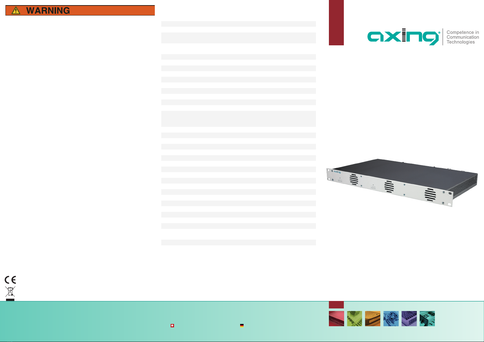
MIE 3-02 | MIE 6-02
MIE 3-02/48 | MIE 6-02/48
premium-line
IP to DVB-T2
8Kext | 49,8 Mbps
Quick start guide
Technical data:
Safety advices:
The installation of the device and repair work on the device must be carried
out only by a professional in accordance with the applicable VDE directives.
In case of incorrect installation, no liability is assumed.
Never open the device. There are no parts to be maintained by the user inside
the device, however, lethal voltages are present. This also applies to cleaning
the device or working on the connections.
Use only the mains cable enclosed to the device. Never replace any parts
or make any modifications to the mains cable. Otherwise, there is a risk of
death.
If you intend not to use the device for a longer period of time, we recom-
mend you to completely disconnect the device from the mains for safety
reasons and for saving energy by pulling out the mains plug.
Let the device adjust to the room temperature before commissioning, in
particular if condensation is present on the device, or if it was exposed to
large temperature fluctuations.
The device must be operated only in moderate climate.
The device must be operated only in dry rooms. In damp rooms or outdoors,
there is a risk of short-circuits (attention: risk of fire) or electrical shocks
(attention: risk of death).
The device shall not be exposed to dripping or splashing. Do not place
objects filled with liquids such as vases on the device.
Plan the mounting or installation location such that you can easily reach the
mains plug and interrupt the electric circuit in dangerous situations. Select
the mounting or installation location such that children cannot play near the
device and its connections without supervision. The mounting or installation
location must allow a safe installation of all connected cables. Power supply
cables and supply cables must not be damaged or squeezed by any objects.
Operate the device only on a flat, firm surface and protect it against uninten-
tional movements.
Never expose the device to direct solar irradiation and avoid direct vicinity of
heat sources (e.g. heaters, other electrical appliances, fireplace, etc.). It must
be always ensured that devices with cooling elements or ventilation slots are
not covered or obstructed.
Ensure generous air circulation around the device. This will prevent possible
damage to device and risk of fire due to overheating. Mounting in a 19“
rack, there must be at least 5 cm clearance in front of and behind the unit.
It must be always ensured that cables are not located near heat sources (e.g.
heaters, other electrical appliances, fireplace, etc.).
In particular, the warranty and liability shall be excluded for the consequenc-
es of incorrect use, in case of incorrect modifications or repair work carried
out by the customer. Use the device only as described in the operating
instructions and in particular according to the state-of-the-art.
The DVB-C/T network must be installed and grounded according to the
current DIN EN 60728-11 standard.
Herewith AXING AG declares that the marked products comply with the valid
guidelines.
WEEE Nr. DE26869279 | Electrical and electronic components must not be
disposed of as residual waste, it must be disposed of separately. Note: You find the detailed technical data by entering the article in the search field at
www.axing.com.
Type MIE 3-02 MIE 6-02
IPTV input
Supported input transport
streams SPTS, MPTS (CBR/VBR)
Max. number
(outofSPTSorMPTS) 512 2×512
Supported protocols IP V4; UDP; RTP; IGMP v2, v3
Total net data rate 1 × 900 Mbps 2 × 900 Mbps
Output
Number of channels 1 × 3 × DVB-T2 2 × 3 × DVB-T2
Frequency range 109…862 MHz
Channel bandwidth 7 MHz, 8 MHz
Possible frequency shift -4…+4 MHz (0.5 MHz steps)
Connector 1 × F-female 2 × F-female
Output level adjustable 85…105 dBµV
Output modulation
Compilance
EN 50083-9 | ETSI TS 101 154 | ETSI EN300 429 |
ETSIEN300 744
DVB-T2 acc. to EN 302 755, mode A (single PLP)
Type QPSK, QAM16, QAM64, QAM256
Supported output formats MPEG-2/H.262, MPEG-4/H.264 and HEVC/H.265
MER ≥ 43 dB
BER ≥9x10⁻⁹
Shoulder attenuation ≥ 56 dB
C/N ≥45 dB
Reflection >14 dB
Bit rate, max 49,8 Mbps
FFT 1K, 2K, 4K, 8K, 8Kext mode
FEC 1/2, 3/5, 2/3, 3/4, 4/5, 5/6
Guard interval 1/4, 19/128, 1/8, 19/256, 1/16, 1/32, 1/128
Interfaces
IPTV intput 1 x RJ45 2 x RJ45
CAS/IPTV (redundant) 1 x RJ45 2 x RJ45
Compilance IEEE 802.3, 1000 Base-T (GigE)
Configuration/CAS 1 × RJ-45 2 × RJ-45
Compilance IEEE 802.3, 10/100 Base-T
General
Operation voltage 100…240 VAC/50…60 Hz
48 VDC
Power consumption 30 W 60 W
Operating temperature range
(acc.toEN60065) –10°C…+50°C
Product description:
MIE 3-02 Includes 1 module, supports SPTS and MPTS (also mixed),
transmodulates max. 512 input streams in 3 DVB-T2 output
channels.
MIE 6-02 Includes 2 modules, supports SPTS and MPTS (also mixed),
converts a maximum of 2 × 512 input streams into 2 x 3 DVB-T2
output channels.
9MIE 3-02 and MIE 6-02 includes two power supplies for 100…240VAC.
9MIE 3-02/48 and MIE 6-02/48 includes two power supplies for 36…60
VDC.
Scope of delivery:
1 × IP to DVB-T2
2 × AC power cord
1 × Quick start guide
Note:
You can call up the detailed operation instructions for download by entering
the article in the search field at www.axing.com.
Mounting and Installation:
Before mounting and installation, pull the mains plug!
Mounting in a 19“ rack
For 19-inch rack mounting, there must be at least 5 cm clearance in front of
and behind the unit.
Slide the device into the 19 „rack.
Fix the device with four screws.
Equipotential bonding
The device must be connected to the equipotential bonding according to
EN 60728-11.
Use the equipotential bonding connection at the device.
To connect the outer conductor of the coaxial cable to the equipotential
bonding, use e.g. QEW earthing angles or CFA earth connection blocks.
Power supply 100…240 VAC
Connect both power supplies with the enclosed cables to 100…240VAC.
Power supply 36…60 VDC
The power supply input connectors are 2 × M4 screws
Connect the DC connectors to 36…60 VDC.
Important: Ensure that the polarity is correct. Use sufficient conductor
cross sections.
IPTV input
Connect the IPTV input to an Ethernet switch connected to the IPTV source.
Use Class 5/6 Ethernet cables with RJ-45 connectors.
RF output
Connect the output (RF OUT) of the device to the established distribution
network. Use a high-shielded coaxial cable with an F connector.
Configuration:
The device is configured via the graphical user interface. To access the
user interface, you need a standard PC/laptop with a network interface, a
commercially available network cable and the actual version of the installed
web browser.
The MIE 3-02 includes one module A
Default IP address of module A: 192.168.0.145
Subnet mask: 255.255.255.0
The MIE 6-02 includes two modules A and B. Each module has its own
configuration interface and its own IP address.
Default IP address of module A: 192.168.0.145
Default IP address of module B: 192.168.0.148
Subnet mask: 255.255.255.0
Accessing the configuration interface:
Change the IP address of your PC/laptop, e.g. to 192.168.0.11, subnet
mask: 255.255.255.0
Connect the PC to the RJ-45 Ethernet connector Control.
Enter the IP address of the connected module in the web browser.
The configuration screen is password-protected:
Enter the default password Ramsen8262 (after the first log-in, the
password should be changed).
Click the „Enter password“ button.
This will open the start page.
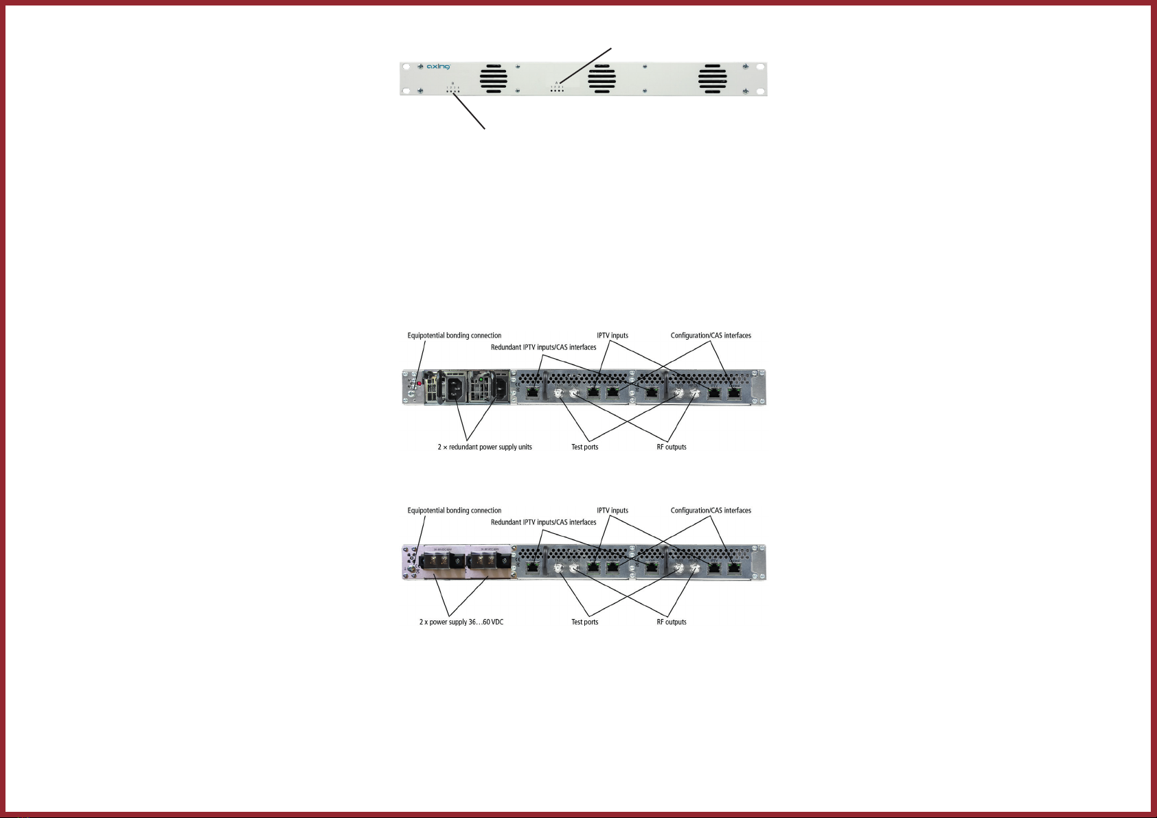
Display elements
LEDs 1…3
of modul B (MIE 6-02)
LEDs 1…3
of module A (MIE 3-02/6-02)
The LEDs show the state of the output modulators:
9When a modulator is filled with content and the modulator is not overloa-
ded, the corresponding LED lights up green.
9If a modulator is on but not filled (without content), the corresponding LED
flashs.
9If a modulator is overloaded (too much content), the LED lights up red.
9In case a modulator is turned off, the corresponding LED is off.
Connectors
MIE 3-02 and MIE 6-02
MIE 3-02/48 and MIE 6-02/48
Upgrading MIE 3-02:
The MIE 3-02 can be extended by a further module MIM 3-02.
Disconnect the device from the mains.
Disassemble the cover plate on the back.
Insert the module carefully.
The module noticeably snaps into the contacts.
Screw the module with the screws of the cover plate.
Then reconnect the device.
Configure the new module in the same way as module B in the MIE6-02.
Other manuals for MIE 3-02
1
This manual suits for next models
3
Table of contents
Languages:


