5
SHEILDING GAS
The gas provides a shield over the weld pool to prevent
contamination from the surrounding air. The shielding
gas also contributes to arc stability, weld strength and
appearance, so care should be taken to ensure that the
correct gas type/mixture is selected for the metal being
welded. (Refer table page 10)
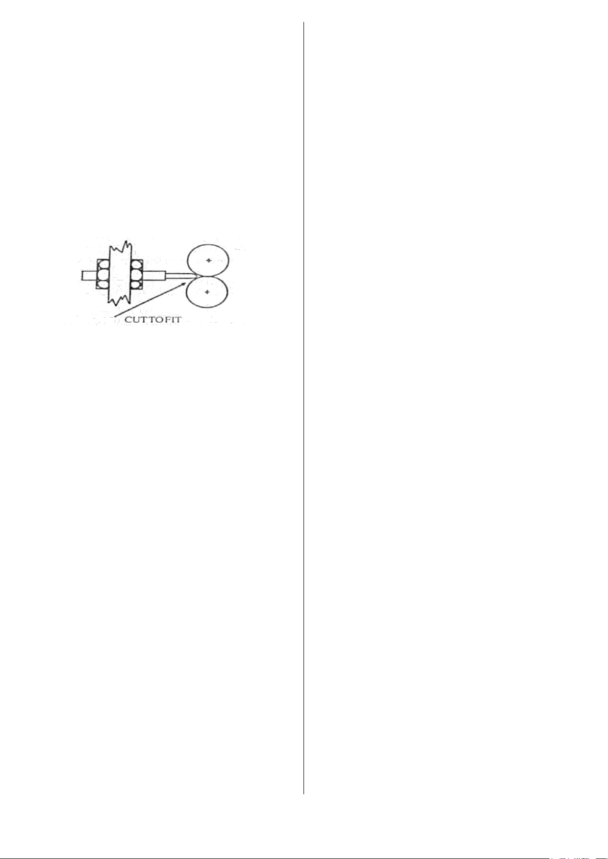
The gas flow rate, adjusted by the regulator, increases
with variations in welding gun diameter and should be 15
litres per minute for the MB24 welding gun to 25 litresper
minute for the MB36 welding gun with cylindrical nozzle.
Excessive gas flow rates should be avoided as they are
wasteful and, in some instances, can cause weld
porosity.
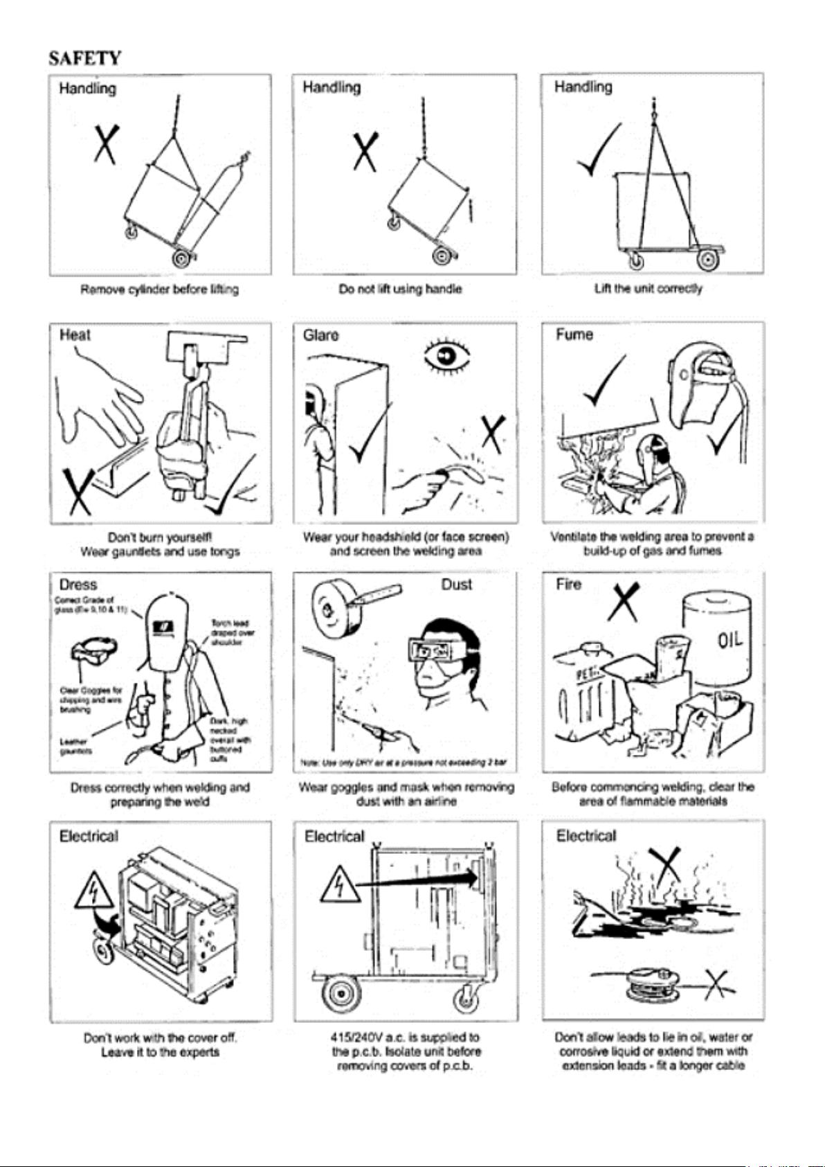
WORK ENVIRONMENT
The machine should be used indoors away from strong
draughts which may cause gas dissipation.
If the machine is to be covered, the natural cooling air
circulation must not be interrupted.
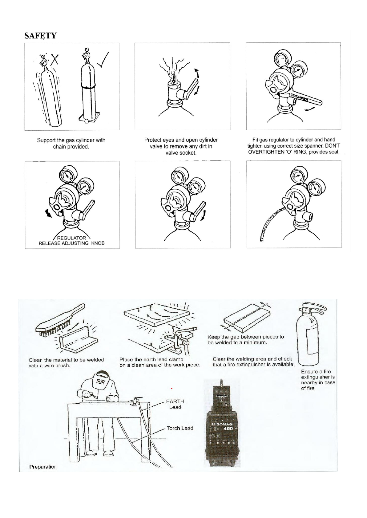
Before commencing welding, clear area of flammable
materials.
OPERATION
1. Continuous Welding
Ensure that both timer switches ‘t1’ and ‘t2’ are in the
“OFF” position.
Set the voltage and wire feed controls to positions
suitable for welding the thickness of the material being
welded.
Welding current varies in direct relationship to wire feed
speed. For low welding current output, the wire feed
speed control should be set at the low end of the wire
feed speed scale.
Turning the wire feed speed control knob clockwise will
result in increased wire feed speed and welding current.
Welding voltage is adjusted to match the wire feed speed
(welding current).
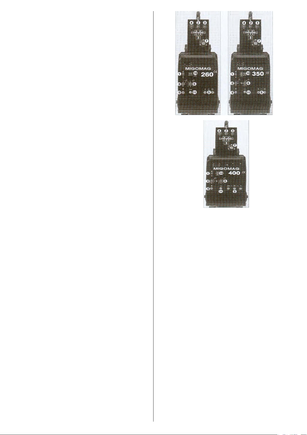
For welding in the low current range, set both voltage
switches to position number (1). (number 1 on both
voltage switches for MIGOMAG 260, 350, 400)
These MIGOMAG machines have two voltage selection
switches, a course control (8) and fine voltage selection
(6).
Progressively select higher voltage positions with
increases in wire feed speed.
Low wire feed speed settings for a given voltage will
cause a large ball to form on the end of the welding wire
and cause excessive spatter.
High wire feed speed settings for a given voltage will
cause wire stubbing.
Position the torch over the seam to be welded with the
nozzle approximately 70° to the work surface.
The nozzle to work distance should be approximately
10mm.
WARN BYSTANDERS TO SHIELD THEIR EYES.
Lower your helmet and press the welding gun trigger
switch to initiate an arc.
As the weld is deposited, push the torch from right to left
direction, slowly along the seam at a constant speed.
Using the wire feed speed control, adjust for a “crisp”
sounding arc.
2. Spot Welding
MIG spot welding is made from one side of the sheets
placed upon another so that the high welding current
penetrates through the upper sheet (max. 1.5mm) and
a part of the lower sheet.
A circular spot is produced each time the torch trigger
is pressed. The spot weld time ‘t1’ can be varied.
Select ‘spot’ welding by turning switch ‘t1’ only.
Fit spot weld nozzle to the torch.
Set voltage and wire feed speed controls to near
maximum settings and carry out test welds on scrap
materials as follows:
Position the legs of spot-welding nozzle over weld
position and depress torch trigger switch. `At the
termination of the weld, check for weld penetration
(small dimple showing on underside of weld), and
adjust spot weld time for best results.
When welding sheets of unequal thickness, the thinner
sheet must be on top. Thicker sheets can be welded
together by drilling a hole in the top sheet and directing
the wire into hole –this is known as ‘plug welding’.
Spot welding requires ONLY LIGHT PRESSURE; the
sheets are pressed against each other with the legs of
the welding nozzle.
3. Stitch Welding
The wire feed output is switched on and off repeatedly.
This produces a lower heat input which is particularly
advantageous when welding thin or poor-quality
materials as well as bridging gaps.
Select ‘stitch’ welding by turning ’t1’ and ‘t2’ controls to
the halfway setting. Vary time to obtain the best results.
They do not have to be equal.
‘t1’ controls the welding or working cycle.
‘t2’ controls the pause cycle between welding.
Note: The trigger on the gun must be kept
depressed during both cycles.
Welding occurs during the working (ON) cycle; During
the pause cycle, the wire feed STOPS, and the arc will
extinguish. During the pause cycle the molten pool will
cool down. The arc will ignite again automatically at the
beginning of the following working cycle when the filler
wire makes contact with the molten pool. The welding
current is automatically switched on and off and the
shielding gas supply will remain on during the pause
cycle.
Note: Spot welding and stitch welding of
aluminium is not possible.