Axminster AHDP13B User manual

Pillar Drills
User manual
AHDP13B Code 101925
AHDP16B Code 101926
AHDP16F Code 101927
AHRD16B Code 101928
AHRD16F Code 101929
AXMINSTER
SERIES
Hobby
AT&M: 27/10/2016
REF: 101974
Code
101925
Code
101926
Code
101927
Code
101928
Code
101929

Index of Contents
2
Declaration of Conformity
Copied from CE Certificate
The undersigned, T. Fuhrmann and Matthias Grzam
Authorised by Manufactured by
Laizhou Planet Machinery Co., Ltd.Yutai West Street
Laizhou, Shandong 261400 P. R. China
Model Number: ZQJ4113A, ZQJ4116Q,
ZQJ4116A, ZQJ3116, ZQJ3116A
Manufactured by Laizhou Planet Machinery Co., Ltd. is in
compliance with the standards determined in the following
Council Directive.
EC Council Directive 200/42/EC
Warning The symbols below advise that you follow
the correct safety procedures when using
this machine.
Fully read manual
and safety instructions
before use
Eye protection
should be worn
Ear protection
should be worn
HAZARD
Motor gets hot
Dust mask
should be worn
Index of Contents 02
Declaration of Conformity 03
What’s Included 04-05-06
General Safety Instructions 06-07
General Safety Instructions for Drilling Machines 07
Specification 08
Assembly 09-10-11-12-13
Illustration and Parts Description 14-15-16-17
Changing the Speed 18-19
Removing the Keyless Chuck 19
Maintenance 20
Speed Select Tables 21
Drill Speed Material Table 22
Troubleshooting 23
Exploded Diagram/Parts List 24-25-26-27-28-29-31-32-33
Wiring Diagram 34
CE Certificate 35-36-37
Notes 38-39

What’s Included
3
Quantity Item Part
1 No AHDP13B Small Bench Pillar Drill A
Quantity Item Part
1 No AHDP16F Floor Pillar Drill C
Quantity Item Part
1 No AHRD16F Floor Radial Drill E
Quantity Item Part
1 No AHDP16B Medium Bench Pillar Drill B
Quantity Item Part
1 No AHRD16B Bench Radial Drill D
Model Number ZQJ4113A
Model Number ZQJ4116A
Model Number ZQJ3116A
Model Number ZQJ4116Q
Model Number ZQJ3116
A B CDE
Box Containing:
1 No Pillar for drill head complete with mounting
flange, rise and fall rack and retaining ring 1
1 No Drill table with mounting flange 2 (101926 ONLY)
2a (101925 ONLY)
1 No Drill table extension bracket arm 2b (101927 and 101929 ONLY)
2c (101928 ONLY)
1 No Extension bracket arm 2d (101928 and 101929 ONLY)
1 No Drill table square 2e (101928 ONLY)
Drill table round 2f (101927 and 101929 ONLY)
1 No Base 3
1 No Pillar drill head 4
1 No Radial drill head with spacer block 4a (101928 and 101929 ONLY)
1 No Drill guard assembly 5
3 No Lever feed handles 6
1 No Keyless chuck 3-16mm 7
Keyless chuck 1-13mm 7 (101925 ONLY)
1 No Morse taper arbor for chuck assembly 8
1 No Crank handle for table rise and fall mechanism 9
Lift and shift handle clamps for the rise and
fall mechanism, drill table and radial drill
head column clamps 10
1 No Morse taper drift 11
4 No M8 x 20mm + washers 12 (101926 and 101928 ONLY)
4 No M8 x 35mm +washers 12 (101927 and 101929 ONLY)
3 No M8 x 20mm + washers 12 (101925 ONLY)
2 No Hex Keys 3-4mm 13
2 No Table clamping threaded bolts washers 14 (101927 and 101929 ONLY)
and wing nuts

What’s Included
4
1
2 3
4a
2c
4

What’s Included
5
2b
2e
2d
2a
5
6
10
9
7 8
13
11
12
2f

What’s Included
6
14
10
General Safety Instructions
Work Place/Environment/Installation
Mains Powered Machines/ Primary Precautions
These machines are supplied with a moulded 13 Amp plug
and 3 core power cable. Before using the machine inspect the
cable and the plug to make sure that neither are damaged. If
any damage is visible have the machine inspected/repaired
by a suitably qualified person. If it is necessary to replace the
plug, it is preferable to use an ‘unbreakable’type that will resist
damage. Only use a 13 Amp plug, make sure the cable clamp
is tightened securely. Fuse at 13 Amp. If extension leads are to
be used, carry out the same safety checks on them, and ensure
that they are correctly rated to safely supply the current that
is required for your machine. It is also recommended that the
power supply outlet is the switched type, and that the supply is
switched off whilst plugging in, or unplugging the machine.
General Instructions for 230V Tools
Good Working Practices/Safety
The following suggestions will enable you to observe good
working practices, keep yourself and fellow workers safe and
maintain your tools and equipment in good working order.
WARNING! KEEP TOOLS AND EQUIPMENT OUT
OF THE REACH OF YOUNG CHILDREN!
Work Place/Environment
DO NOT use when or where it is liable to get wet. If the machine
is to be used outside and it starts to rain stop work and move it
inside. If machine has got wet; dry it off as soon as possible, with
a cloth or paper towel.
DO NOT use 230V a.c. powered machines anywhere within a
site area that is flooded or puddled, and do not trail extension
cables across wet areas.
KEEP the machine clean; it will enable you to more easily see
any damage that may have occurred.
CLEAN the machine with a damp soapy cloth if needs be, do
not use any solvents or cleaners, as these may cause damage to
any plastic parts or to the electrical components.
KEEP the work area as uncluttered as is practical, this includes
personnel as well as material.
WARNING! UNDER NO CIRCUMSTANCES SHOULD
CHILDREN BE ALLOWED IN WORK AREAS!

General Safety Instructions
7
It is good practice to leave the machine unplugged until work
is about to commence, also make sure to unplug the machine
when it is not in use, or unattended. Always disconnect by
pulling on the plug body and not the cable.
Once you are ready to commence work, remove any tools used
in the setting operations (if any) and place safely out of the
way. Re-connect the machine. Carry out a final check e.g. check
the drill bit is securely tightened in the machine, check you
have the correct speed and function set, check that the power
cable will not ‘snag’ etc.
Make sure you are comfortable before you start work,
balanced, not reaching etc. If the work you are carrying out
is liable to generate flying grit, dust or chips, wear the appro-
priate safety clothing, goggles, gloves, masks etc. If the work
operation appears to be excessively noisy, wear ear-defenders.
If you wear your hair in a long style, wearing a cap, safety hel-
met, hairnet, even a sweatband, will minimise the possibility of
your hair being caught up in the rotating parts of the machine.
Likewise,consideration should be given to the removal of rings
and wristwatches, if these are liable to be a‘snag’hazard.
Consideration should also be given to non-slip footwear, etc.
DO NOT work with cutting or boring tools of any description
if you are tired, your attention is wandering or you are being
subjected to distraction. A deep cut, a lost fingertip or worse is
not worth it!
DO NOT use this machine within the designated safety areas of
flammable liquid stores or in areas where there may be volatile
gases.There are very expensive, very specialised machines for
working in these areas, THIS IS NOT ONE OF THEM.
CHECK that drills are the correct type and size, are undamaged
and are kept clean and sharp, this will maintain their operating
performance and lessen the loading on the machine. Above all,
OBSERVE…. make sure you know what is happening around
you, and USE YOUR COMMON SENSE.
General Safety Instructions for Drilling Machines
1. DO NOT operate the machine without carrying out
a preliminary inspection.
2. CHECK that the speed is correct for the planned operation,
and the upper drive belt cover is closed and fastened secure.
3. CHECK the drill bit is the correct size and type, is correctly
fitted and tightened in the chuck.
4. Make sure that the drillhead, the table bracket arm, the table
tilt and the table swivel clamps are all locked before any drilling
is attempted.
5. DO NOT attempt to carry out any drilling operation on
material that has not been secured to the drill table, either by
vice or clamp.
6. Remove any tools (chuck key, spanners etc), that may have
been used in setting up operations and put them away in their
correct stowage positions.
7.Try to arrange the drilling operation so that the drill tip does
not come in contact with the table.
8. ALWAYS allow the drill to stop before removing drills or swarf
from around the job or the table.
9. NEVER remove‘flying’swarf strands from the drill whilst it is
turning.
10. It is a good precaution to wear eye protection when drilling,
especially using small drills, or very hard material that produces
small chips.
11. It is not a good idea to wear gloves when
operating a drill press.
12. After the job is completed, remove all tools and accessories
from the machine, check that drill bits are still sharp and re-use
able.
13. Clean the machine down thoroughly, including removing
coolant or cutting compounds from the drill table.
14. Lightly coat all metal surfaces with a light oil coating.
15. Disconnect the machine from the supply. Secure the cable/
plug clear of the floor.

Specification
8
Code 101928
Model AHRD16B
Power 375W 50Hz (230V 1ph)
Speed Range (5) 500-2,450rpm
Swing 840mm
Chuck Cap/Type 3-16mm Keyless
Throat 420mm
Taper MT2
Chuck Travel 80mm
Horizontal Arm Travel 320mm
Diameter of Column 60mm
Max Chuck to Table 220mm
Max Chuck to Base 375mm
Table Tilt -45˚ to +45˚
Base Size 450 x 270mm
Quill Diameter 40mm
Table Size 230 x 210mm
Overall L x W x H 840 x 320 x 790mm
Weight 37kg
Code 101927
Model AHDP16F
Power 375W 50Hz (230V 1 ph)
Speed Range (12) 210-2,580rpm
Swing 330mm
Chuck Cap/Type 3-16mm Keyless
Throat 165mm
Taper MT2
Chuck Travel 80mm
Diameter of Column 70mm
Max Chuck to Table 890mm
Max Chuck to Base 1,125mm
Table Tilt -45˚ to +45˚
Base Size 420 x 250mm
Collar Diameter 60mm
Quill Diameter 40mm
Table Table 310mm diameter
Overall L x W x H 560 x 330 x 1,580mm
Weight 60kg
Code 101925
Model AHDP13B
Power 250W 50Hz (230V 1 ph)
Speed Range (5) 600 - 2,500rpm
Swing 210mm
Chuck Size 1.5-13mm Keyless
Chuck Travel 50mm
Diameter of Column 46mm
Max Chuck to Table 285mm
Max Chuck to Base 380mm
Table Tilt -45˚ to +45˚
Base Size 285 x 185mm
Collar Diameter 46mm
Quill Diameter 45mm
Table Size 165 x 165mm
Overall L x W x H 500 x 280 x 735mm
Weight 26kg
Code 101926
Model AHDP16B
Power 375W 50Hz (230V 1 ph)
Speed Range (12) 210-2,580rpm
Swing 254mm
Chuck Cap/Type 3-16mm Keyless
Throat 127mm
Taper MT2
Chuck Travel 60mm
Diameter of Column 60mm
Collar Diameter 60mm
Max Chuck to Table 315mm
Max Chuck to Base 430mm
Table Tilt -45˚ to +45˚
Base Size 340 x 210mm
Quill Diameter 40mm
Table Size 240 x 240mm
Overall L x W x H 530 x 280 x 840mm
Weight 37kg
Code 101929
Model AHRD16F
Power 375W 50Hz (230V 1ph)
Speed Range (5) 500-2,450rpm
Swing 840mm
ChuckCap/Type 3-16mm Keyless
Throat 420mm
Taper MT2
Chuck Travel 80mm
Horizontal Arm Travel 320mm
Diameter of Column 60mm
Max Chuck to Table 680mm
Max Chuck to Base 1,180mm
Table Tilt -45˚ to +45˚
Base Size 450 x 270mm
Quill Diameter 40mm
Table Size 310mm diameter
Overall L x W x H 820 x 320 x 1,630mm
Weight 61kg

Assembly
9
PLEASE DISPOSE OF THE PACKAGING RESPONSIBLY;
MUCH OF THE MATERIAL IS RECYCLABLE
The machine and its accessories will arrive coated with heavy
corrosion preventative grease and greased wax paper or plastic
wrapping.These will need to be cleaned from the machine, its
components and accessories prior to it being set up and
commissioned. Use water soluble de greaser to remove the
barrier grease. Be warned, it will stain if you splash it on
clothing etc. After cleaning, lightly coat the exposed metal
WARNING! WEAR OVERALLS, RUBBER GLOVES
AND EYE PROTECTION!
surfaces of the machine with a thin layer of light machine oil.
N.B If you used water soluble de greaser make sure you apply
this thin film sooner rather than later.
Please read the Instruction Manual prior to using your new
machine; as well as the installation procedure, there are
daily and periodic maintenance recommendations to help
you keep your machine on top line and prolong its life.
Keep this instruction manual readily accessible for any
others who may also be required to use the machine.
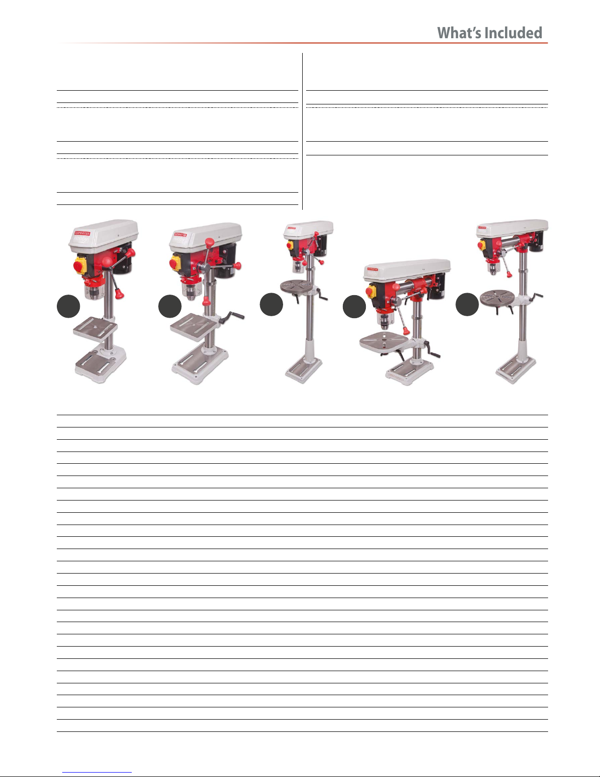
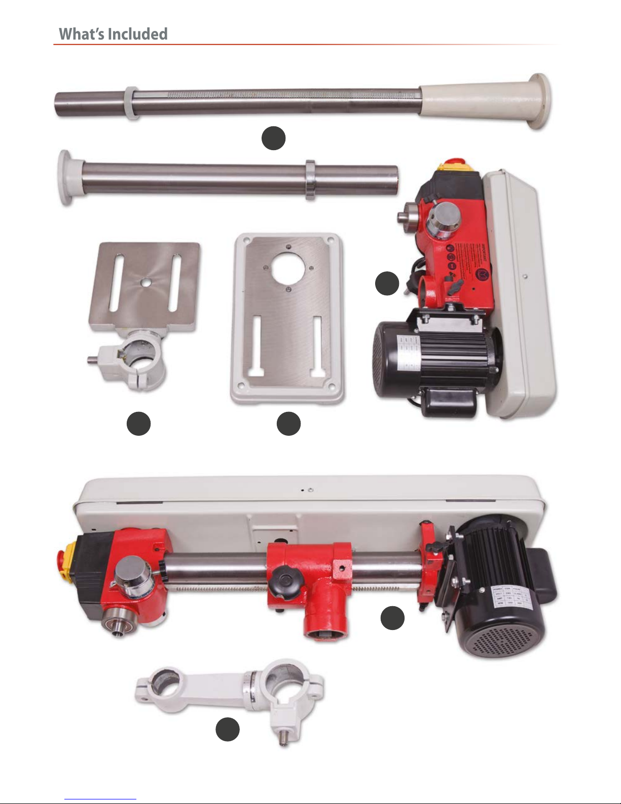
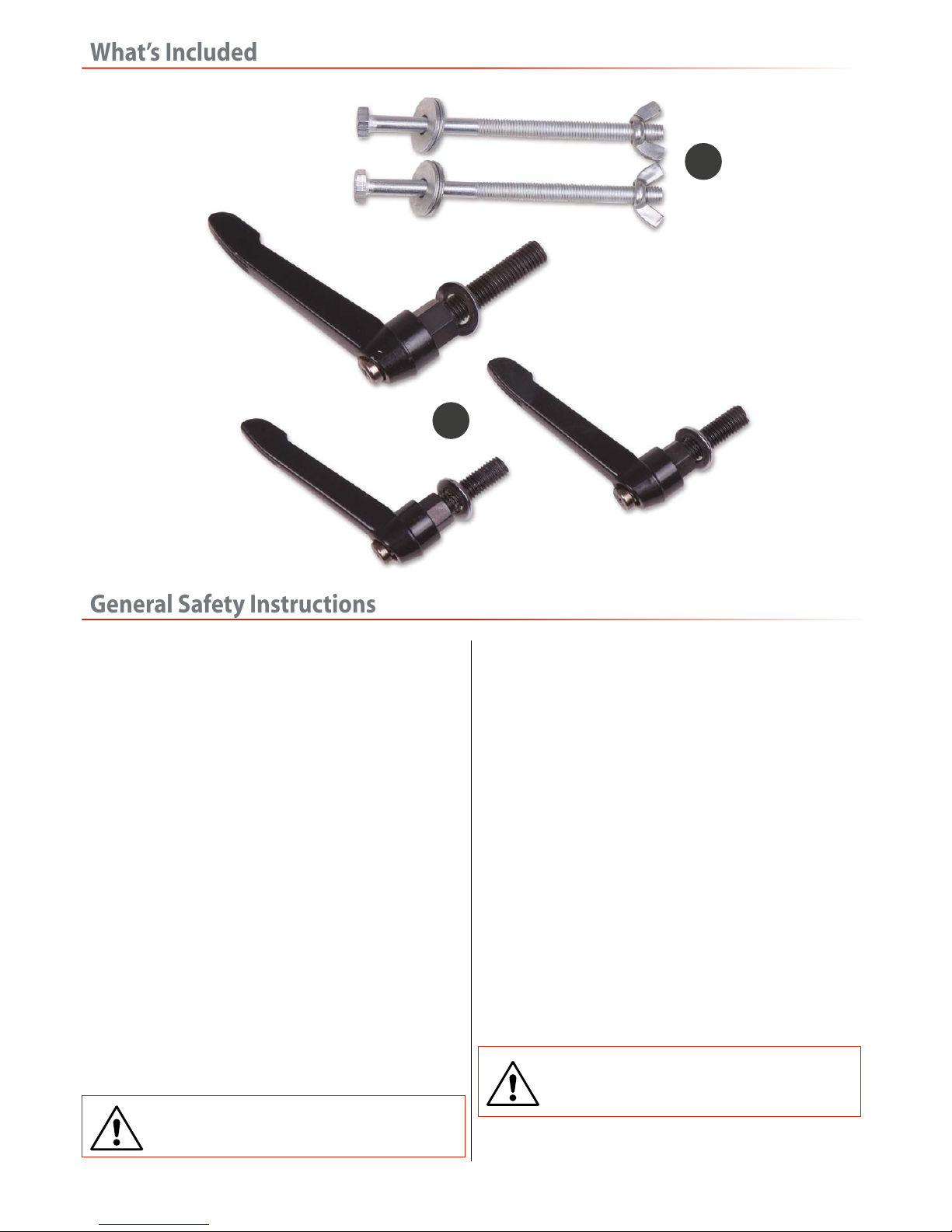
Having unpacked your machine and its accessories, please
check the contents against the equipment list ”What’s Included”,
if there are any discrepancies, please contact Axminster Tool
Centre using the procedures laid down on our website.
Please read through the section entitled illustration and
parts description, to identify the parts quickly and easily.
WARNING! THE DRILL HEAD IS A HEAVY AND
SUBSTANTIAL PIECE OF MACHINERY,YOU ARE
ADVISED TO HAVE HELP TO LIFT IT CLEAR OF THE
BOX AND FIT IT TO THE COLUMN.
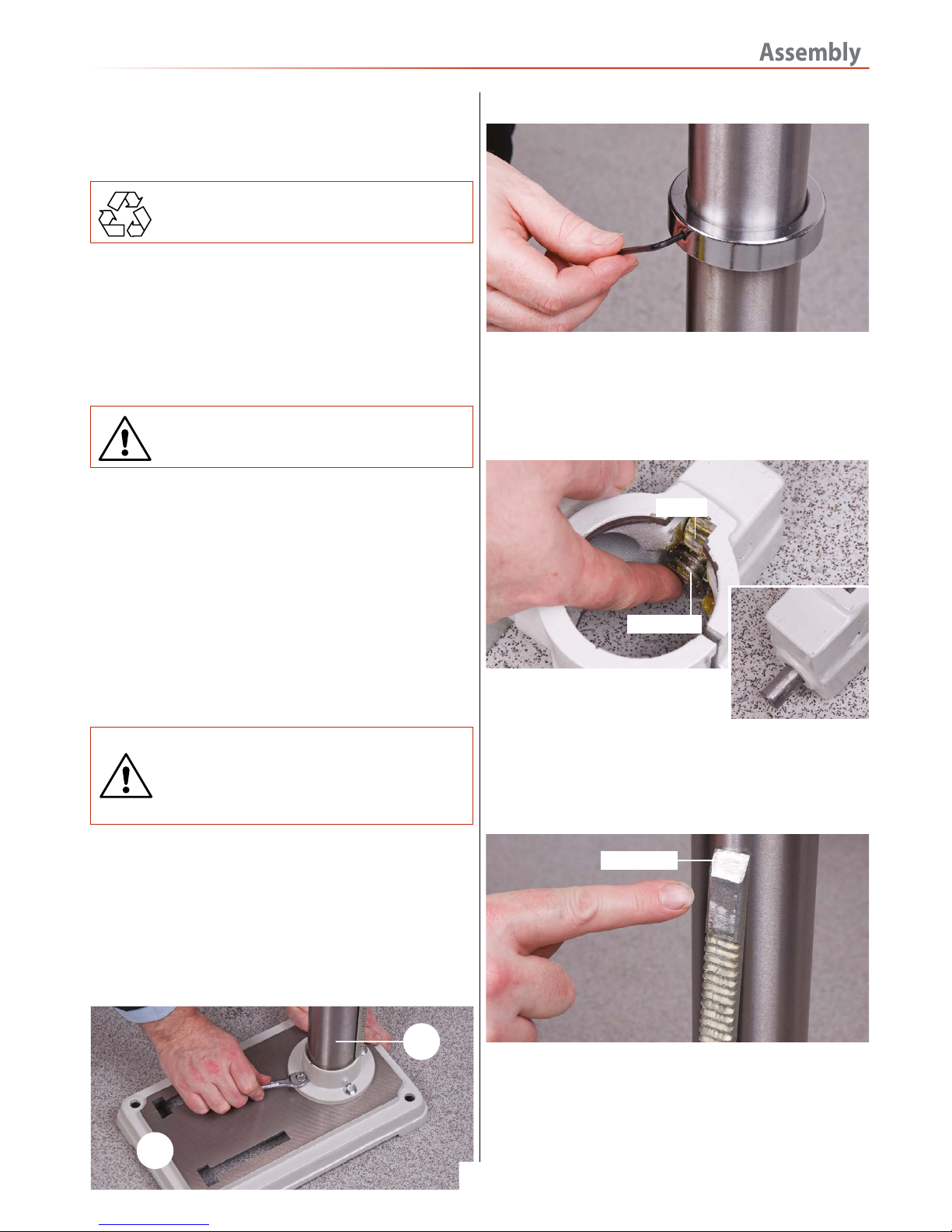
1. Place the base (3) on the bench or floor and place the
mounting flange of the column (1) onto the seating flange of
the base, align the holes. Use the four Hex bolts and secure the
column to the base, see fig 1. Loosen the grub screw holding
the chamfered retaining collar on the column with the supplied
Hex key, place it and the rise and fall rack assembly aside,
see fig 2.
Fig 01
Fig 02
2. Take the drill table mounting bracket arm (2,2a,2b,2c) and
twist the worm drive shaft with your fingers so that the whole
shaft protrudes from the casting and the worm gear
itself is clear of the square recess in the main body of the
casting (see fig 3). Fig 03-04
3. Pick up the rise and fall gear rack,
identify the top and the bottom, (the
rack gearing is cut asymmetrically, with
the gear cut extending closer to the bottom), make sure you
have the rack the right way up, as it will allow you to drive the
drill table up and down over its full range, see fig 5.
Fig 05
4. Fit the rise and fall rack into the square recess in the
mounting body casting, ensure that it is engaged with the
pinion, see figs 6 and lower the combined mechanism over the
column (1). Allow it to slide down the column until the rise and
fall rack is located in the cup chamfer in the top of the mount-
ing flange, see figs 7. Replace the cup chamfered retaining
3
1
Worm gear
Pinion
Top of rack
Worm gear shaft
Continues Over....

Assembly
10
collar over the column and slide it down onto the top of the
rack. Lock it in place with the grub screw, ensuring that it has
captured the upper end of the rack securely, but not too tight
that the rack cannot be swivelled around the pillar see fig 8 .
Fig 06-07
Fig 08
5. Locate and fit the crank handle (9) to the shaft, ensuring that
you tighten the grub screw onto the machined flat on the shaft,
this will keep the worm gear in position, see figs 9-10.
Fig 09
6. Check that the bracket can be driven up and down the
column and can swivel around the pillar. Locate the lift and shift
clamping handle (10) and screw it into the threaded hole to the
rear of the mounting bracket arm (2) and tighten, see fig 11.
Check it has ‘pinched’up on the column and the bracket is
immobile; both in its up and down travel and swivel movement.
Fig 11
7. Slot the drill table (2e or 2f) into the machined hole to the
front of the mounting arm (2b and 2c) and screw a lift and shift
clamping handle (10) into to the threaded hole beneath the
table and tighten, see figs 12-13. Check it has ‘pinched’ up on
the drill table spigot and the drill table is immobile.
Radial and Floor Standing Drills Only
Fig 12-13-14
Rise and fall rack
cup chamfer
Machined flat
9
10
2f
2e

Assembly
11
Note: On the two radial drills fit the extension arm (2d) into
the mounting arm (2b and 2c) then the tables, see figs 14-
15-16.
Fig 15-16
1. CHECK the drill head, ensure that the two hex socket grub
screws that lock the head in place on the column are
withdrawn and will not foul on the column (1) when the head
is fitted, see fig 17. Put the lower assembly you have just been
working on in the designated position, make sure it is stable
and lift the drillhead (4) over the column (1) and let it drop into
place, see fig 18. Set the drill head approximately fore and aft
and lock in position using the two cap head grub screws
mentioned earlier, see fig 19. Check that the drillhead is
immobile. Everything on the drilling machine is now secured.
Mounting the Drill Head
Fig 17-18-19
2. Lay the drill head on its side, locate the column
spacer block and insert it into machined recess inside the base
of the drill head, see fig 20. Lift the drill head onto the column
as described above and secure using a lift and shift handle (10),
see figs 21. Fig 20
Radial Pillar Drill Head Only
10
2d
10
Grub screw
4
Spacer block
Continues Over....

Assembly
12
NOTE: Make sure the spacer block does not come out when
lifting the drill head onto the column!
Fig 21
Fig 22
3. Locate another lift and shift handle (10) and screw it into the
threaded hole for the Horizontal clamp assembly, see fig 22.
4. Open the pulley cover and check to see if the belt has been
tensioned. If not, loosen the two motor yoke locks and push the
motor back to tension the belt, see fig 23-24-25. For the floor
standing pillar drill head, move the tensioning lever back then
re-tighten the motor yoke locks to lock the motor in place, see
fig 24-25.
Fig 25-26
Fig 25-26
1-13mm Keyless Chuck AHDP13B Only
3-16mm Keyless Chuck
Locate the chuck (7) and insert it up over the morse taper arbor,
using a high faced mallet, lightly tap it home.
Locate the morse taper arbor (8), insert the arbor into the
keyless chuck (7) then slot the assembly up into the quill.
Using a high faced mallet, lightly tap it home., see fig 27-28.
Fig 27-28
10
10
Motor yoke clamp
Motor yoke clamp
Tensioning lever
8
7

Assembly
13
Drill Guard
Locate the drill guard assembly (5), loosen the Phillips screw
and nut to the rear of the guard, see fig 29 insert the assembly
up over the lower bearing flange of the quill until the assembly
is up against the drill casting, re-tighten the screw and nut to
lock the guard assembly in place, see fig 30.
Fig 29-30
Lever Feed Handles
Locate the three lever feed handles (6) and screw them into the
threaded holes on the depth stop ring, see fig 31-32.
Fig 31-32
A B
C
D
E
Model Letter
AHDP13B A
AHDP16B B
AHDP16F C
AHRD16B D
AHRD16F E
5
6
6

Illustration and Parts Description
14
101925 Drive Pulley
101925 AHDP13B
101926 AHDP16B
101926 Drive Pulley 101927 Drive Pulley
101927 AHDP16F
Pulley drive belt cover
Motor yoke locking knob
Motor
Belt cover securing screw
Lever feed handle
Retaining collar
Crank handle
Rise and fall rack
Mounting flange
Base casting
Micro switch
Drill table
Keyless chuck
Chuck guard
ON/OFF switch shroud
Drill column
Base casting ‘T’ slot
Pillar drill securing holes

Illustration and Parts Description
15
Depth stop clamp (A)
Depth scale (B), Depth scale pointer (C)
ON/OFF switch (A)
Emergency stop button (B)
Motor yoke clamp (A)
Table tilt locking bolt 90˚ Locking bolt Motor yoke clamp (A)
Drive belt tensioning lever (B)
Table tilt scale (A)
Table tilt pointer (B)
Depth stop assembly (A)
Depth stop scale (B), Depth stop nuts (C)
Pointer (D)
Quill rise and full return spring (A)
B
A
C
A
B
B
A
A
B
A
B
A
A
CD
B

Illustration and Parts Description
16
Pulley drive belt cover
Horizontal column
Horizontal column lock
Vertical scale
Motor yoke locking knob
Motor
Lever feed handle
Retaining collar
Crank handle
Rise and fall rack
Mounting flange
Lift and shift handles
Base casting ‘T’ slot
Base casting
Motor pulley
Pulley belt
Quill pulley
Pillar drill securing holes
Drill table
Extension arm Extension bracket arm
Keyless chuck
Chuck guard
ON/OFF switch shroud
Drill column
101929 AHRD16F
101928 AHRD16B
Micro switch

Illustration and Parts Description
17
Vertical scale (A)
Column pointer (B)
Horizontal column adjusting knob (A)
Horizontal column clamping handle (B), Motor yoke clamp (C)
Turn the horizontal adjusting knob
anti-clockwise to move the column forward
Turn the horizontal adjusting knob
clockwise to move the column back
Vertical locking pin
Loosen the horizontal column clamping handle (B).Pull out the vertical locking pin to
un-lock the drill head column. Rotate + or - to the appropriate angle using the tilt pointer on
the column then retighten the horizontal clamping handle to lock the head in position.
Table tilt scale (A)
Table tilt pointer (B)
B
A
B
A
C
BA

Changing the Speed
18
WARNING! DISCONNECT THE PILLAR DRILL FROM
THE MAINS SUPPLY BEFORE CONTINUING!
1. Locate and loosen the motor yoke locks (A). Locate the drive
belt tensioning lever (B), see fig 33.Turn it clockwise, to move
the motor assembly“in”. This will release the tension from the
drive belts, see fig 34.
Fig 33-34
AHDP16F Pillar Drill Only
All other Pillar Drills
2. Refer to the (speed select table) and ascertain the belt
positions for the speed you require. Move the belts to these
positions.
WARNING! TAKE CARE NOT TO TRAP YOUR FINGERS
WHEN REPOSITIONING THE BELT ON THE PULLEYS!
WARNING! TAKE CARE NOT TO TRAP YOUR FINGERS
WHEN REPOSITIONING THE BELT ON THE PULLEYS!
Turn the pulley train,see fig 35 to check the belts move freely.
Tension the whole belt train by turning the drive belt
tensioning lever (B) anti-clockwise, to move the motor
assembly“out”. Tighten the motor yoke butterfly knobs (A)
to lock the motor assembly in position.
Fig 35
A
B
To release the tension, loosen the two motor yoke locks on
either side of drilll head, push the motor assembly up against
the drill head casting, thus releasing the tension on the pulleys,
see figs 36-37.
Refer to the (speed select table) and ascertain the belt positions
for the speed you require.
Fig 36-37
AHDP13B Drive Pulley
AHDP16B Drive Pulley
AHDP16F Drive Pulley
loosen

Changing the Speed
19
Radial Drills
To release the tension, loosen the motor yoke tensioning locks,
push the motor up against the drillhead casting, thus releasing
the tension on the pulleys, see fig 38-39.
Fig 38-39
WARNING! TAKE CARE NOT TO TRAP YOUR FINGERS
WHEN REPOSITIONING THE BELT ON THE PULLEYS!
Turn the pulleys to check the belts move freely.Tension the
pulleys by pushing the motor assembly out and securing the
motor yoke butterfly knob to lock the motor assembly in
position. Lower the belt and pulley cover carefully, (remember
the micro switch).
RE-CONNECT THE SUPPLY AND SWITCH ON. CHECK
THE DRILL RUNS SMOOTHLY, NO HARD VIBRATION
ETC.
If all seems satisfactory, recommence drilling operations.
Removing the Keyless Chuck
Motor yoke lock
1. Lower the quill to its maximum depth by turning the lever
feed handle. While holding the handle turn the depth scale ring
(A) fully round and then tighten the butterfly depth stop clamp
(B) to lock the quill in position, see fig 40.
Fig 40
2. Place a piece of timber on the drill table to prevent the chuck
from being damaged.
3.While holding the handle in place turn the chuck to line up
the morse taper arbor in the quill’s machined slot, see fig 41.
Insert the morse taper drift (11) in the quill’s slot, thus pushing
the morse taper down and releasing the chuck, see fig 42-43.
Fig 41-42-43
Morse taper arbor
Depth scale ring
Quill slot
11

Maintenance
20
Excessive dust in the motor can cause excessive heat to
develop. Every effort should be made to prevent foreign
material from entering the motor.
When operated under conditions likely to permit
accumulations of dust, dirt or waste, a visual inspection should
be made at frequent intervals. Accumulations of dry dust can
usually be blown out successfully.
Caution:To avoid eye injury or adverse reaction to dust,
high pressure hoses should not be used especially in poorly
ventilated areas.The operator performing this cleaning
function should wear safety goggles and dust filter mask.
After cleaning apply a light coat of machine oil on the quill and
chuck.
If the machine is going to stand idle for any length of time, a
light coat of spray or machine oil over the column and table
will prevent rusting.Then place a dust sheet over the pillar drill.
WARNING! DISCONNECT THE MACHINE FROM THE
MAINS SUPPLY BEFORE CONTINUING!
Cleaning
WARNING! DO NOT USE THE MACHINE IF THE
POWER CABLE HAS BECOME DAMAGED
Electric
If any servicing (other than the above cleaning) becomes
necessary, the unit should be returned to Axminster Tool Centre
to be repaired by one of our qualified electricians. Contact our
customer sales department for further assisance on 03332
406406 or email as @ csaxminster.co.uk .
Call: 03332 406406
Email: cs@axminster.co.uk
WARNING! DO NOT ATTEMPED TO REPAIR IT
YOURSELF CONTACT OUR TECHNICAL SALES TEAM
FOR ASSSISTANCE!
Motor speed
The speed of the motor cannot be regulated or changed - no
adjustment is necessary.
Oil Points
This manual suits for next models
4
Table of contents
Other Axminster Drill manuals

Axminster
Axminster Pillar Drills User manual

Axminster
Axminster AW16BMST User manual

Axminster
Axminster Engineer RDP20B User manual

Axminster
Axminster AC285PD User manual

Axminster
Axminster D.R.O. Micro Drill User manual

Axminster
Axminster Engineer Series User manual

Axminster
Axminster ATDP13B User manual

Axminster
Axminster AP340PD User manual

Axminster
Axminster SX2.7 User manual

Axminster
Axminster SB-25AV User manual