Axminster AW12BM User manual

100081
AW12BM 12mm
Bench Morticer
Axminster Reference No: AW12BM
User Manual
WHITE
AXMINSTER
W
www.axminster.co.uk

Page No.
Index of Contents
02
The undersigned, F. Nispel authorised
by Laizhou Chunlin Machinery Factory, No. 275 Wenquan East
Road, Laizhou, Shandong 261400
P.R. China
declares that this product:
Morticer
MS3612
manufactured by Laizhou Chunlin Machinery Factory is in
compliance with the following standards or standardisation
document in accordance with Council Directives
Low Voltage Directive 73/23/EEC
Amended by EEC Directive 93/68/EEC
Declaration of Conformity
Index of Contents................................................................................................................................................2
Declaration of Conformity
………….………........……..………….....................................................................2
What’s in the Box………….………........……..………….......................................................................................3
Initial Actions......................................................................................................................................4
General Instructions for 240v Machines........................................................................................4,5
Initial Assembly...............................................................................................................................5,6
Specifications
….………........……..………….....................................................................................................6
Machine Illustration of the 12mm Bench Morticer............................................................................7
Parts Identification and Description..................................................................................................8
Machine Illustration of the 12mm Bench Morticer (continued)....................................................... 9
Parts Identification and Description (Continued)...........................................................................10
Machine Illustration of the 12mm Bench Morticer (continued)..................................................... 11
Parts Identification and Description (Continued)...........................................................................12
Machine Illustration of the 12mm Bench Morticer (continued)..................................................... 13
Setting up the Machine......................................................................................................... 14,15,16
General Precautions Whilst Using a Drilling Machine...............................................................16,17
Maintenance.................................................................................................................................... 17
Illustrated Parts Beakdown for the 12mm Bench Morticer............................................................18
Illustrated Parts list for the 12mm Bench Morticer.........................................................................19

Quantity Item Model Number
1 No. Mortising Machine Base with Mounting Columns, Plunge Depth Stops,
Balance Spring, Head Box, Chisel Adaptor, Chuck and
Fence Mounting Block assembled MS3612
1 No. 12mm Auger Chisel and Bit Set
1 No. Composite Board Machine Table
1 No. Back Fence with Main Mounting and Hold Down Mounting Rods Fitted
1 No. Large Tensioning Spring
1 No. Lift and Shift Locking Handle
1 No. Fence Adjusting Assembly
1 No Hold Down Yoke
1 No. Accessories Rack with 2 Large Panhead Screws
1 No. Small ‘P’ Clip
1 No. Rod Lever Handle
1 No. Small Tensioning Spring
1 No. Large Head Machine Screw
1 No. Grip Sleeve
1 No. 1-13mm B6 Drill Chuck
1 No. B6 to Parallel Chuck Mounting Shaft (For Drilling Operations)
Tool Packet
1 No. 4mm Allen Key
1 No. 5mm Allen Key
1 No. 6mm Allen Key
1 No. Spring Nose Chuck Key
1 No. Plastic Tube (Dust Extractor Connector) and Short Bolt
2 No. Countersunk Screws (Secure Down Machine Table)
1 No. Small Light Fitting on Flexi-Conduit with Fixing Bracket Attached
1 No. Lift and Shift Handle
1 No. Guarantee Card
1 No. Instruction Manual
What’s in the Box?
03

Good Working Practices/Safety
The following suggestions will enable you to observe good working practices, keep yourself and fellow
workers safe and maintain your tools and equipment in good working order.
WARNING!! KEEP TOOLS AND EQUIPMENT OUT OF THE REACH OF YOUNG CHILDREN
Work Place/Environment
The machine is not designed for working outside, do not use when or where it is liable to get wet. If the
machine does get wet; dry it off as soon as possible, with a cloth or paper towel. Do not use 240Va.c.
powered machines anywhere within a site area that is flooded or puddled, and do not trail extension cables
across wet areas. Keep the machines clean; it will enable you to more easily see any damage that may
have occurred. Clean the machine with a damp soapy cloth if needs be, do not use any solvents or
cleaners, as these may cause damage to any plastic parts or to the electrical components.
General Instructions for 240v Machines
!
04
Initial Actions
Having unpacked your machine and its accessories, please check the contents against the
equipment list ”What’s in the box”, if there are any discrepancies, please contact Axminster
Power Tool Centre using the procedures laid down in the catalogue. Please dispose of the
packaging responsibly; much of the material is bio-degradable. The machine and its accessories
will arrive coated with heavy corrosion preventative grease and greased wax paper. These will
need to be cleaned from the machine, its components and accessories prior to it being set up
and commissioned. Use coal oil, paraffin or a proprietary degreaser to remove the barrier grease.
Be warned, it will stain if you splash it on clothing etc.; wear overalls, coverall et al., rubber
gloves are also a good idea, as is eye protection if your cleaning process tends to be a little bit
enthusiastic. After cleaning, lightly coat the exposed metal surfaces of the machine with a thin
layer of light machine oil. N.B If you used paraffin/kerosene make sure you apply this thin film
sooner rather than later.
Please read the Instruction Manual prior to using your new machine; as well as the
installation procedure, there are daily and periodic maintenance recommendations to
help you keep your machine on top line and prolong its life. Keep this Instruction Manual
readily accessible for any others who may also be required to use the machine.
Work Place/Environment/Installation
Mains Powered Machines
Primary Precautions
These machines are supplied with a moulded 13 Amp. Plug and 3 core power cable. Before
using the machine inspect the cable and the plug to make sure that neither are damaged. If any
damage is visible have the machine inspected/repaired by a suitably qualified person. If it is
necessary to replace the plug, it is preferable to use an ‘unbreakable’ type that will resist
damage. Only use a 13 Amp plug, make sure the cable clamp is tightened securely. Fuse at 13
Amp. If extension leads are to be used, carry out the same safety checks on them, and ensure
that they are correctly rated to safely supply the current that is required for your machine. It is
also recommended that the power supply outlet is the switched type, and that the supply is
switched off whilst plugging in, or unplugging the machine.
!

05
General Instructions for 240v Machines (Continued)
Keep the work area as well lit and uncluttered as is practical, this includes
personnel as well as material.
Under no circumstances should CHILDREN be allowed in work areas.
It is good practice to leave the machine unplugged until work is about to commence, also make
sure to unplug the machine when it is not in use, or unattended. Always disconnect by pulling on
the plug body and not the cable. Once you are ready to commence work, remove any tools used
in the setting operations (if any) and place safely out of the way. Re-connect the machine.
Carry out a final check e.g. check the cutting tool, drill bit etc., is securely tightened in the
machine, check you have the correct speed and function set, check that the power cable will not
‘snag’ etc.
Make sure you are comfortable before you start work, balanced, not reaching etc.,
If the work you are carrying out is liable to generate flying grit, dust or chips, wear the
appropriate safety clothing, goggles, gloves, masks etc., If the work operation appears to be
excessively noisy, wear ear-defenders. If you wear your hair in a long style, wearing a cap, safety
helmet, hairnet, even a sweatband, will minimise the possibility of your hair being caught up in
the rotating parts of the tool, likewise, consideration should be given to the removal of rings and
wristwatches, if these are liable to be a ‘snag’ hazard. Consideration should also be given to
non-slip footwear, etc.
Do not work with cutting or boring tools of any description if you are tired, your
attention is wandering or you are being subjected to distraction. A deep cut, a lost
fingertip or worse; is not worth it!
Do not use this machine within the designated safety areas of flammable liquid
stores or in areas where there may be volatile gases. There are very expensive, very
specialised machines for working in these areas, THIS IS NOT ONE OF THEM.
Check that cutters, drills etc., are the correct type and size, are undamaged and are kept clean
and sharp, this will maintain their operating performance and lessen the loading on the machine.
Above all, OBSERVE…. make sure you know what is happening around you, and USE YOUR
COMMON SENSE.
!
!
!
!
!
Initial Assembly
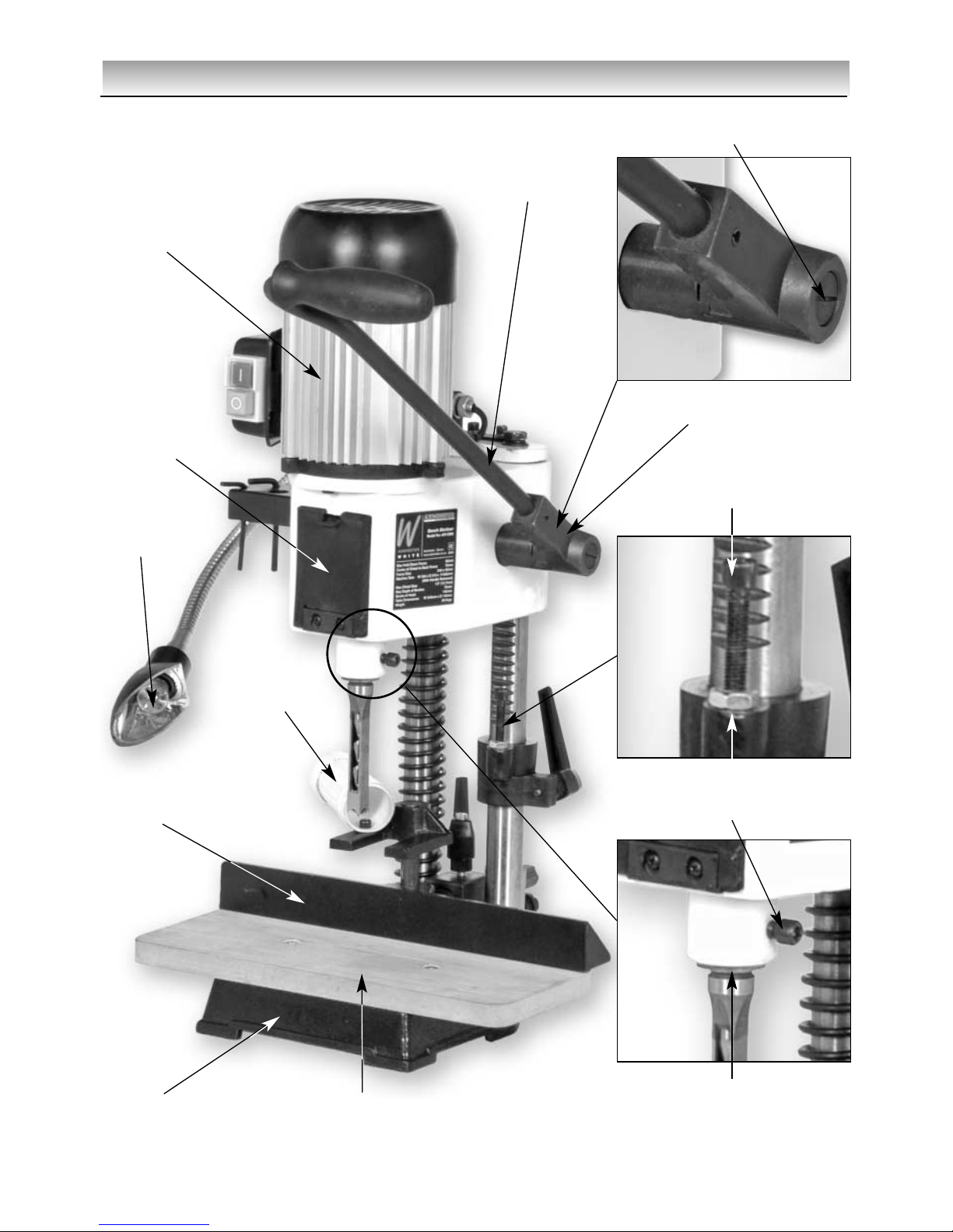
Please take some time to read the section entitled “Identification and Parts
Description” to identify the various parts of your machine so that you familiar with the
terminology we will use to enable you to set up and operate your Morticer safely and
correctly.
1) Place the machine onto a suitable surface, at a height that will enable you to work comfortably.
Locate the machine table and the 2 No. countersunk screws. Place the table on the base and
fasten down using the 2 No. screws. Locate and remove the two caphead bolts from the holes to
the rear left of the tool post column bridge, lift the lamp fitting and locate the mounting bracket
over the holes, re-insert the bolts and tighten securely. Remove the fitted ‘P’ clip and screw, snap
the clip over the cable and resecure.

06
Specifications
Axminster No. (100081) AW12BM
Rating: Light Trade
Motor: 240V a.c. 50 Hz 370W
Chisel Stroke: 110mm
Centre of Chisel to Back Fence: 95mm
Max Height of Timber with 12.7mm Chisel and Bit: 120mm
Max Chisel Size Softwood: 12.7mm
Max Chisel Size Hardwood: 12.7mm
Overall L x W x H: 350 x 350 x 600mm
Weight 25kg
Initial Assembly of the Machine (Continued)
2) Locate the Accessory tray, the small ‘P’ clip and the three small panhead screws. Locate the 3
No. threaded holes in the rear upper left side of the headbox. Snap the ‘P’ clip on the cable, tidy’
the mains cable away from the front of the machine, and secure into the most forward threaded
hole. Offer up the accessory tray and secure using the remaining two panhead screws, into the
threaded holes.
3) Locate the backfence and its associated components. Fit the lift and shift clamping handle into
the back fence mounting block, leave the housing clear to fit the main mounting bar of the back
fence. Fit the large spring over the main mounting bar, introduce the bar into the mounting block
and push home, put the spring under some tension and tighten down the clamping handle.
Located the ‘fine adjust’ assembly over the main bar and secure in place by tightening the socket
grubscrew. Turn the adjusting bolt until the bolt is in contact with the mounting block. Unlocking
the clamping lever handle should enable the back fence to be adjusted back and forth using the
adjusting bolt ‘with’ or ‘against’ the tension in the spring.
4) Locate the handle and the grip sleeve, fit the sleeve over the handle. (If it is difficult to slide on,
try lubricating with a small amount of washing up liquid. Locate the small spring and the large
headed screw. Place the handle over the rise and fall shaft, fit the spring over the large head
screw shaft and screw into the end of the rise and fall shaft. The spring pressure should be
enough to keep the castellated dogs of the handle and the rise and fall shaft together under
normal operation, but allow the dogs to be disengaged to re-position the handle. Exercise the
headbox up and down and check everything works satisfactorily.
5) Locate the hold down yoke, fit over the rod fitted upright in the backfence casting,
secure in place using the socket grubscrew. Locate the dust extraction pipe and the short
caphead bolt. The pipe is located onto the hold down yoke using the bolt into a pre-threaded
hole in the top of the left arm of the hold down yoke.

07
Machine Illustration of the 12mm Bench Morticer
Fig 1
Base casting Mortising table
Motor
Lamp
Dust
extraction
tube
Backfence
Depth stop bolt
Chisel clamping bolt
Chisel mounting flange
Fig 1a
Fig 1b
Fig 1c
Chuck
access door
Lock nut
Plunge lever
assembly
Large head
machine screw
Rise and fall
Mechanism

08
Parts Identification and Description
Please take some time to identify the various parts of your machine so that you
are familiar with the terminology we will use to enable you to set up and operate your
morticer safely and correctly.
Base Casting This is the ‘Stand’ for the mortising m/c. It has a square flat table machined at
(See fig 1) the front, onto which a machine table board can be fitted. There are several
holes and slots in the base through which you could fasten the base to a
bench or similar to give added stability if you so desire. At the rear of the
base are the housings for the tool posts.
Fine adjusting The fine adjusting system consists of a metal plate bored through to fit over
system the backfence main mounting bar, beyond the mounting block. The plate is
(See fig 2c) held in position by a grubscrew threaded through the wall of the hole and
screwed down against the main mounting bar. There is also a threaded hole
through the plate, through which a long star knobbed bolt is fitted. This bolt
acts against the lower part of the backfence mounting block and is used to
adjust the backfence against the spring tension. If the reach of the bolt is
exceeded during adjustment, the plate can be further adjusted along the main
mounting bar.
Mortising table The Mortising table is a piece of composite board which is screwed down to
the (See fig 1) base casting to provide a large flat area on which to mount the work piece.
Counterbalance A large coil spring is mounted over the left hand side tool post column. It acts
spring between the machine base and the underside of the headbox, and in
(See fig 2) compression, acts as a counterbalance to the weight of the headbox
assembly.
Double depth Two ring collars that fit over the right hand side tool post column below the
stop head box. The lower collar has a threaded through hole into which a lift and
(See fig 2) shift lever handle bolt is inserted. Tightening this bolt will clamp the collar into
position on the tool post column and govern the position of the upper collar.
The upper collar has a bolt with a lock nut threaded into the upper face of the
collar, this bolt can be adjusted and locked. Turning the head of the nut under
the head box, or turning the head of the bolt out from under the head box will
give two separate plunge depths.
Backfence This is a casting with a machined front face and a flat underside. There is a
(See fig 1) large land in the middle of the casting behind the front face; this land has the
main mounting bar fitted to it, which extends to the rear; and is fed through
the backfence mounting block. There is a tension spring fitted concentrically
over the bar, which is compressed between the rear of the back fence and the
front of the backfence mounting block, which is part of the fence adjusting
system. There is also a housing machined in the top front of the land; into this
housing the support rod for the hold down is fitted; it can be adjusted in
height over part of its length and is held in place by a grubscrew inserted
through the wall of the housing.
Backfence This is a large block mounted on the base between the tool post columns. It
mounting block has a hole bored through it to accept the main mounting bar of the back
(See fig 2) fence. There is a tapped hole through the top wall of the hole into which a lift
and shift locking handle is fitted, to secure the backfence at its required
dimension.
!

09
Machine Illustration of the 12mm Bench Morticer (continued)
Backfence
mounting
block
Shift lever
handle
Counterbalance
spring
Double
depth stop
Motor
Light assembly
Fine adjusting system
Locking handle
Metal plate
Scale
Star knob bolt
Grubscrew
Chisel
Tool post column
Fig 2
Fig 2a
Fig 2c
Fig 2b
Tool post column bridge
Castellated dog

10
Parts Identification and Description (Continued)
Tool post Two steel shafts mounted into the rear of the base casting, they are the
columns ‘runners’ for the headbox. They are ‘bridged’ at the top to increase accuracy
(See fig 2) and rigidity, The machine lamp is mounted on the bridging lozenge. The right
hand column has a rack cut in the surface which engages with a pinion in the
headbox assembly to provide the rise and fall action. The double depth stop
collar is also mounted on the right hand side column below the headbox.
The left hand column carries the counterbalance spring.
Headbox This is the ‘morticing machine’ and the descriptions of its various
parts and components are detailed as follows:-
Headbox The main casting to which all the components are attached. The headbox has
casting two sleeve housings machined at the rear, which allows the casting to be
(See fig 3) fitted to the Tool Post Columns.
The motor Standard 240V 50Hz single phase four pole motor rated at 370W, mounted on
(See fig 3) the top of the headbox.
Auger mounting A 12mm drill chuck that is mounted directly onto the motor shaft. Access for
chuck the chuck key is via a door in the front of the headbox.
(See fig 3b)
On/Off switch The switch assembly is mounted in a box which is bolted to the side of the
assembly Motor. The two button switches are marked with the standard ‘O’ for stop
(See fig 3a) and ‘I’ for start. The assembly is an NVR type so any loss of the supply
during operation, when re-established, will not cause the motor to restart.
Rise and fall There is a housing machined on each side of the the headbox which mounts
mechanism a through shaft. A pinion gear is mounted on the shaft inside the headbox
(See fig 1) and meshes with the rack cut into the tool post column. Driving the pinion
shaft will cause the headbox to rise and fall up and down the tool post
columns. The end of the shaft protruding from the headbox has a castellated
dog mounted over it which is pinned through to prevent slip, through the
centre of the dog is a threaded hole to enable the plunge lever assembly to
be mounted to it.
Plunge lever The associated part of the rise and fall mechanism is the plunge lever handle
assembly assembly. This consists of a tube, shaped and bent to provide a handle. The
(See fig 1) end of the handle which mounts onto the rise and fall shaft has a castellated
dog and a locating boss. There is a through hole in the boss, one end of the
boss is the mating castellated dog that meshes with the dog on the pinion
shaft; the other end is recessed to house the fixing bolt and the retaining
spring. The fixing bolt goes through the boss into the rise and fall shaft,
tensions the spring which holds the castellations engaged. To move the
handle to a different position, disengage the dogs by pulling them apart
(against the spring) move the handle to the desired position, and allow the
spring to re-engage the dogs. There is a grip sleeve that fits over the handle
itself, to provide a firmer grip and some cushioning to the hand.

11
Machine Illustration of the 12mm Bench Morticer (continued)
On
Off
NVR on/off switch assembly
Motor
Headbox
casting
Chuck door removed
for clarity
Grip Sleeve
Handle
Auger mounting chuck
Backfence
mounting block
Spring
Fig 3
Fig 3a
Fig 3b
Fig 3c

12
Parts Identification and Description (Continued)
Hold Down Yoke This is a small ‘U’ shaped yoke casting. The underside of the arms of the ‘U’
(See fig 4b) are flat, to rest on the workpiece. In the middle of the yoke is a land
sufficiently large enough to be bored through to accept the mounting rod.
There is a grubscrew threaded through the wall of the hole so that the hold
down can be secured in position.
Chisel mounting The chisel mounting flange is a raised annular housing machined at the
flange bottom of the headbox. It has a 3/4" adaptor pressed into it, which is used to
(See fig 1c) clamp the chisels in position. It is also used to mount the guard when the
morticer is used in ‘Drill’ mode.
Chuck access Access to the chuck for loosening or tightening is via a rectangular hole in
door the front of the headbox casting. This hole is covered by a hinged door. The
(See fig 1) door is held closed by a sprung catch moulded into the door.
Accessory A plastic block, with various holes moulded into it to allow the chisel sets,
mounting panel chuck key, allen keys etc, of the machine tool kit, to be stowed safely out of
(See fig 4a) the way but close to hand.
Chuck guard A hinged and telescopic guard that is fitted to the headbox lower bearing
(See fig 5a) flange during drilling operations. (Remove the bolt for the chisel clamping) It
has a spring fitted to the hinge geometry to hold the guard “over
centre” to maintain it in the raised or lowered position. The guard shield can
be extended or retracted (telescoped) as required, using the second leaf, the
second leaf is held in position by two butterfly nuts and bolts.
1-13mm/B6 A standard 12mm chuck with an internal B6 taper mount. Used in conjuction
drill chuck` with the mounting shaft to transpose the mortiser into a small drill press.
(See fig 5d)
B6 to parallel The mounting shaft for the drill chuck, the main shaft has a diameter slightly
shank shaft smaller than the adaptor for the chisels.
(See fig 5d,5e)
Accessory mounting panel Hold down yoke
Fig 4
Fig 4a Fig 4b

13
Machine Illustration of the 12mm Bench Morticer (continued)
Morticer converted to a drill press
1-13mm/B6 drill chuck assembly
B6 to parallel chuck mounting shaft
12mm auger chisel & bit set
Drill bit
Auger chisel
1-13mm/B6
drill chuck
Chuck key
Drill press assembly
Fig 5
Fig 5a
Fig 5b
Chisel mounting
clamp bolt
Chuck guard
Chuck mounting
shaft
Fig 5c
Fig 5d
Fig 5e

14
Setting up the Machine
Overview
Unlike the traditional morticing machines, which allow the table to move in 2 axis, i.e. side to side
and front to rear, the table of this morticer does not move at all. The workpiece must be moved to
achieve the side to side movement, and the placement of the back fence simulates the front to
rear movement.
Initial Set up
Introduce the chisel into the adaptor collar, press the auger up into the chuck, tighten the chuck
and withdraw the chuck key. Gently pinch the chisel in place by finger tightening the securing
bolt.
Setting the chisel auger clearance
The old rule of thumb for chisel auger clearance was known as “the one penny width”. This was
achieved by introducing a penny between the locating shoulder of the chisel and the adaptor
face, with the auger locked in place and with the chisel pulled hard down on the auger. The
penny was then removed and the chisel pushed up to the adaptor face and locked in place, this
established the “one penny width” between the chisel and the auger, which for general timbers
and mortice sizes is quite adequate. Traditional mortisers normally had a cross pin in the auger
mounting mandrel, to prevent the auger being pushed back up into the chisel. The mounting
method on the newer mortisers is a chuck. It is well worth taking the extra time and care to
prepare your augers to give the correct ‘reach’ when ‘bottomed’ out in the chuck. This will
prevent the auger being pushed back towards the chisel and altering the clearance setting.
(See fig 6 )
Fig 6

15
Setting up the Machine (Continued)
General Notes
The morticer will generate a lot of ‘grip’ on the chisel, especially the first cut, or if the timber is a
little green. Make sure you use the hold down yoke to help control the timber during the raise
operation of the morticer.
A lot of setting and resetting is required for the various components of the morticer. A lot of the
settings are more easily achieved by measurement from the front edge of the table, and a broad
assumption is made that the front edge of the table is parallel to the face of the backfence. The
table is indeed rectangular, but the edges are not highly precision machined faces, within a 5
decimal place tolerance. If you ascertain that the front edge is NOT, in fact, parallel with the face
of the backfence, putting a permanent mark on each side of the table from where you will carry
out your measurements, will ensure that the discrepancies will be constant and can be added or
subtracted from the initial measurement you establish.
Setting the chisel Square
When the chisel is tightened in the machine it must normally be square to the backfence.
The easiest way to achieve this is to bring the headbox down to bring the chisel as close to the
table as possible, make sure the backfence is locked in place, set a square against the
backfence and set the side of the chisel against the square. and clamp tight. (Remember to have
the chipejection slot in the chisel to the side from which you will cut the mortice).
Setting up the backfence
Usually the easiest method is mark out the mortice, place the workpiece on the table, lined up
under the chisel and then move the backfence to the workpiece and lock it in position. Another
way is by measurement, provided you know where the mortice is to be in the workpiece, the
backfence can be set away from the chisel by measurement, either directly off the backfence or
as a complement figure from the front of the table. A useful accessory for this operation is an
engineers combination square (where the graduated top blade is moveable).
Tip. Because of the necessity of constantly setting and resetting the backfence, it could be very
useful to scribe a series of parallel lines (about 3mm apart?) on the table to aid the setting
operation.
Quick Setting the Backfence/Chisel/Mortice Position
A quick set method for achieving the correct position of the backfence is as follows:-
1. Mark the centre line of the mortice.
2. Lower the headbox so that the auger point just pierces the centre mark, but not so hard that
the workpiece cannot be ‘spun’. Hold the headbox in place.
Note English pattern augers without the centre point can be used by driving the cutting spurs into
the timber. Have care with the smallest chisel sizes and only drive in sufficiently hard for the
auger to lock into the workpiece.
3. Turn the workpiece about the point of the auger until it is approximately parallel with the front
edge of the table, measure from your permanent marks and ‘true up’.
4. Clamp the workpiece in position.
5. Lay the backfence up to the workpiece and clamp that in position.

16
Quick Setting of the Mortice Depth
Put a mark on an easily accessible end of the workpiece to be mortised, at the depth you require.
Pull the headbox down, and put the end of the timber against the chisel, position the headbox so
that the chisel points or the auger point are at the depth required, raise the depth stop collar to
the underside of the headbox and tighten gently. Recheck the depth of the chisel point, if it is
satisfactory tighten securely, if not it can be gently ‘nudged’ down the column with the headbox,
then tighten. Reposition the plunge lever handle to give the most comfortable position and
purchase on the lever, over the full distance of the movement you have just set.
Using the AW12BM as a Drill Press
Warning. Do not work on metal/material that could leave greasy/oily marks,
without removing the mortising table. Refit after drilling operations are complete and the
machine has been thoroughly cleaned of these contaminants. (in respect of timber)
Locate the 1-12mm B6 chuck and the B6 to parallel chuck mounting shaft. Fit the chuck onto the
shaft, secure with a light tap with a hammer? et al.
Remove the chisel from the adaptor in the headbox., clean and put aside, or stow in the
accessories rack. Remove the chisel clamping bolt, (See fig 5) then slide the chuck guard on to
the lower bearing flange of the headbox. (See fig 5a) Introduce the chuck mounting shaft
through the adaptor and up into the auger mounting chuck, (See fig 5b) tighten the chuck
securely onto the parallel shank.
N.B. If you have insufficient reach under the drill chuck, the reach can be marginally increased by
removing the machine table. This will also allow access to the machine base slots to facilitate
clamping the workpiece down etc.
NOTE. Before running the machine in the ‘drill mode’ lightly oil the shaft where it passes through
the chisel adaptor, and exercise/turn the shaft by hand to fully coat the two surfaces.
Setting up the Machine (Continued)
!
General Precautions Whilst Using a Drilling Machine
1. Use the chuck guard.
2. Do not operate the machine without carrying out a preliminary inspection.
3. Remember you only have 1 speed available.
4. Check the drill bit is the correct size and type, is correctly fitted and tightened in the chuck.
Do not overwork the machine, either by drill size or workrate.
5. Do not attempt to carry out any drilling operation on material that has not been secured to the
drill table, either by vice or clamp.
6. Remove any tools (chuck key, spanners etc), that may have been used in setting up
operations and put them away in their correct stowage positions.
7. Always allow the drill to stop before removing drillings or swarf from around the job or the
table.
8. NEVER remove ‘flying’ swarf strands from the drill whilst it is turning.

17
9. It is a good precaution to wear eye protection when drilling, especially using small drills, or
very hard material that produces small chips.
10. It is not a good idea to wear gloves when operating a drill press.
11. After the job is completed, remove all tools and accessories from the machine, check that
drill bits are still sharp and re-useable. Clean the machine down thoroughly, including removing
coolant or cutting compounds from the drill table. Lightly coat all metal surfaces with a light oil
coating. Disconnect the machine from the supply. Secure the cable/plug clear of the floor.
General Precautions Whilst Using a Drilling Machine (Continued)
Maintenance
There is very little maintenance required on your morticer.
Keep it clean
Make sure the rack and pinion gears do not become clogged with chips/sawdust.
Lightly spray oil on all exposed metal surfaces if the machine is going to stand idle for
any length of time. Keep the chisels and augers sharp.
Once a month
Blow/suck the motor to remove any debris that might have lodged in the fan cover. Oil
the chuck and exercise it over its full range to ensure the oil coats all moving parts.
There are full ranges of mortice chisels and a useful sharpening set listed in Section 1 of
the Axminster catalogue.
Oil
OIL

18
Illustrated Parts Beakdown for the 12mm Bench Morticer

19
Illustrated Parts list for the 12mm Bench Morticer
No Description Unit
Motor
Power cord
Chuck
Key
Head
Label
Hex head bolt M8 x 20
Bushing
Guide sleeve
Position plate
Flat washer 10
Hex head bolt M10 x 35
Holder
Cap screw M6 x 25
Flat washer 16
Washer
Hex head screw M6 x 22
Cover
Hinge
Phillips screw M5 x 10
Lower cover plate
Phillips screw M5 x 6
Spring pin 6 x 30
Gear
Hub assembly
Handle assembly
Spring
Shoulder bolt
Spring pin 6 x 20
Grip
Spacing sleeve
Knob
Spindle
Spindle
Spring
1
2
3
4
5
6
7
8
9
10
11
12
13
14
15
16
17
18
19
20
21
22
23
24
25
26
27
28
29
30
31
32
33
34
35
Ref
No Description Unit
Handle assembly
Bolt
Cap screw M8 x 10
Guide
Bracket
Lock washer
Hex head bolt M8 x 15
Table
Hex head screw M6 x 35
Fence
Cap screw M8 x 10
Hold down
Cap screw M8 x 10
Rod
Spring
Lock washer
Hex head bolt M10 x 30
T handle
Cap screw M6 x 30
Bulb cover
Power cord (bulb)
Safety guard
Mounting plate
Power cord clamp
Cap screw M6 x 60
Hex nut M6
Chisel
Cap screw M6 x 12
Handle
Bushing
Power cord clamp
Washer 6
Cap screw
Hex nut
36
37
38
39
40
41
42
43
44
45
46
47
48
49
50
51
52
53
54
55
56
57
58
59
60
61
62
63
64
65
66
67
68
69
Ref

WHITE
AXMINSTER
W
100081
www.axminster.co.uk
Axminster Devon EX13 5PH UK
FREEPHONE 0800 371822
Axminster Reference No: AW12BM
AW12BM 12mm Bench Morticer
This manual suits for next models
1
Table of contents
Other Axminster Drill manuals

Axminster
Axminster Trade AT2001DP User manual

Axminster
Axminster AHDP13B User manual

Axminster
Axminster SX2.7 User manual

Axminster
Axminster ATDP13B User manual

Axminster
Axminster SB-25AV User manual

Axminster
Axminster AW16BMST User manual

Axminster
Axminster Engineer RDP20B User manual

Axminster
Axminster Engineer Series User manual

Axminster
Axminster AP340PD User manual

Axminster
Axminster ZX25M User manual