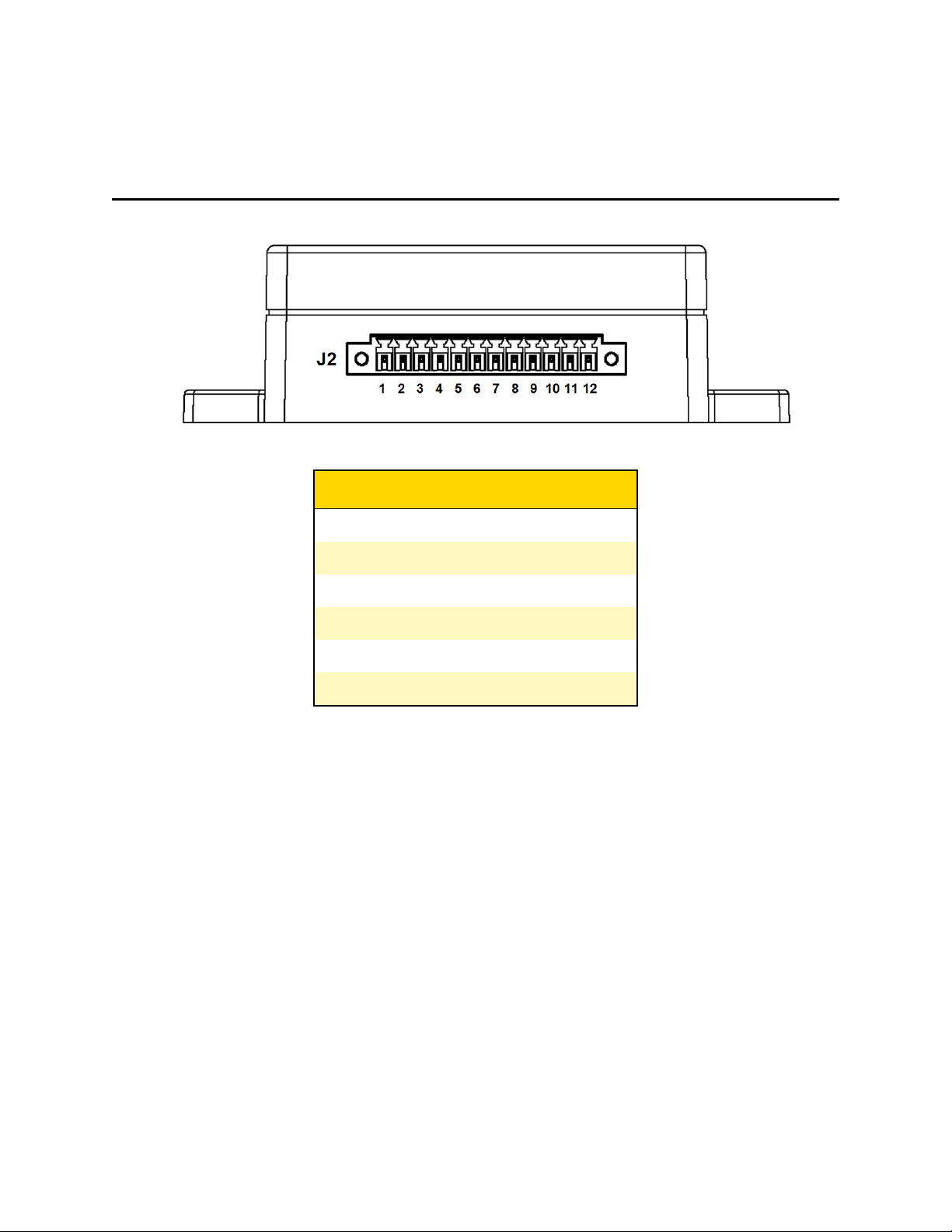
Axon T00504 Manual

Rev: 09 October 2023
Signal Vehicle User
and Installation
Guide
Model: T00504

Signal Vehicle User and Installation Guide
Axon Enterprise, Inc. ii
Axon Enterprise, Inc.
17800 N 85th St
Scottsdale, AZ 85255
USA
, , Axon Evidence, and Axon Fleet are trademarks of Axon Enterprise, Inc., some of which are
registered in the US and other countries. For more information, visit www.axon.com/legal.
All rights reserved. ©2023 Axon Enterprise, Inc..
Bluetooth is a trademark of the Bluetooth SIG, Inc.
Velcro is a trademark of Velcro Industries B.V.
App Store is a trademark of Apple, Inc. registered in the US and other countries.
iOS is a trademark of Cisco Technology, Inc.
Play Store and Android are trademarks of Google, Inc.
Microsoft, Windows, and Internet Explorer are trademarks of Microsoft Corporation registered in the US and
other countries.

Signal Vehicle User and Installation Guide
Axon Enterprise, Inc. iii
Contents
Introduction 1
Additional reading 1
Specifications 1
Pinout table 2
LED indicators 3
Installation 4
Warnings 4
Guidelines 4
Wiring instructions 5
System power (positions 1–2) 5
Ignition enable (position 3) 5
Optional auxiliary enable (position 4) 5
Trigger input (positions 5–12) 5
Update firmware 6
Testing 8
Technical support 8
Warranty 9
Compliance 10
Radio waves 10
Section 8.4 of RSS-GEN 11
Section 8.3 of RSS-GEN 11
Section 6.8 of RSS-GEN 12
Declaration of conformity 12
Compliance marks 12

Introduction
Axon Signal Vehicle is part of a communications platform that, when certain hardware is
activated, transmits a message recognizable by Axon Signal compatible equipment. For
example, when the vehicle light bar is activated, Axon Signal Vehicle can signal all properly
equipped Axon systems within range to begin recording.
Axon systems that work with Axon Signal Vehicle include the Axon Body 2 camera, Axon
Flex 2 system, Axon Fleet 2 system, and all later versions.
Additional reading
If Axon Signal Vehicle is part of an Axon Fleet installation, refer to the appropriate Axon Fleet
Installation Manual for addition information and guidance.
See the Evidence.com User and Administrator Guide for information on
Signal configuration
and
Axon Body Camera Settings
for use with Axon Signal products.
Specifications
Secure Bluetooth transmission 30 seconds
Range of alerted cameras 30+ ft. (9.1+)
Operation input voltage 5.0 VDC – 14.4 VDC
Ignition enable voltage 3.6 VDC – 14.4 VDC
Trigger input voltage 3.6 VDC – 14.4 VDC
Stand-by current
- Ignition on 25 mA (typ)
- Ignition off 25 µA (typ)
Trigger input timing (positions J2-5 thru J2-10)
- Low to high transition 200 ms
- High to low transition 200 ms
Trigger input timing (positions J2-11 thru J2-12)
- Low to high transition 200 ms
- High to low transition 2.5 s*
Signal Vehicle User and Installation Guide
Axon Enterprise, Inc. 1

* This feature is intended to reduce the likelihood of nuisance videos from extraneous triggers caused by some
progressive slide switch control modules. These controllers can cause the input voltage of Axon Signal Vehicle to drop
below 3.6 VDC when transitioning between switch positions.
Pinout table
J2 Position Description
1 Power +12VDC (fuse @ 1A)
2 Ground
3 Ignition enable
4 Auxiliary enable
5–10 Trigger Input
11–12 Trigger input, delayed turn-off
Signal Vehicle User and Installation Guide
Axon Enterprise, Inc. 2

LED indicators
1. Power LED
2. Status LED
Power LED
Color Information
Solid green (on) Axon Signal Vehicle is powered and enabled
Off Axon Signal Vehicle is either not powered or not enabled
Status LED
Color Information
Solid green (on) Operational state (successful boot-up)
Off Check the Power LED
lOff – check power connections
lOn – reboot the device (see Testing and
Troubleshooting) efix
Blinking green* Axon Signal Vehicle is transmitting a detected input signal
* Axon Signal Vehicle must have firmware version 4.2.1 or later for this function.
Signal Vehicle User and Installation Guide
Axon Enterprise, Inc. 3

Installation
Warnings
Failure to follow the instructions in this manual may result in Axon Signal Vehicle not working
properly or cause damage to the device or the vehicle. Save these instructions.
The technician who installs Axon Signal Vehicle must be qualified to work with automotive
electronics.
If mounting Axon Signal Vehicle requires drilling holes, ensure drilling will not damage the
emergency vehicle’s equipment or other vital parts. Remove all burrs and debris after
drilling. Install grommets into all wire passage holes.
Ensure there is a good electrical ground to the vehicle chassis.
If Axon Signal Vehicle is installed in the cab of the vehicle (in a location other than under the
center console), it should be permanently mounted to avoid injury.
Do not install Axon Signal Vehicle anywhere that will interfere with airbag deployment.
Do not install Axon Signal Vehicle where it will be exposed to the elements or extreme heat.
Do not install Axon Signal Vehicle in the vehicle’s engine compartment.
Guidelines
Axon Signal Vehicle is typically installed near the siren or light bar controller (trunk or
console).
Axon Signal Vehicle can be installed using robust double-sided tape, VELCRO® type hook
and loop fastener, or by bolting the device through its mounting flanges (mounting hardware
and electrical supply wiring not included). If using an adhesive to mount the equipment,
thoroughly clean the surface with a 50/50 mixture of isopropyl alcohol and water before
installation.
Axon recommends using gauge 18 AWG wires.
All wires should be connected to the GPIO terminal block interface.
Axon recommends installing a 1-amp fuse, either inline or on a fuse block, for the J2-1
position.
No programming of Axon Signal Vehicle is required for operation. However, have the input
settings reviewed by an Evidence.com administrator. See the Evidence.com User and
Administrator Guide for information on signal configuration.
Signal Vehicle User and Installation Guide
Axon Enterprise, Inc. 4

Wiring instructions
System power (positions 1–2)
Axon recommends using a red wire for the power connection and a black wire for ground
connection.
1. Connect J2-1 to a Positive (+) 12 VDC source from the vehicle battery using an 18 AWG
red wire. Axon recommends installing a 1A fuse, either inline or on a fuse block, for this
position.
2. Connect J2-2 to the vehicle’s chassis ground using an 18 AWG black wire. This is
typically adjacent to the battery.
Ignition enable (position 3)
Connect J2-3 terminal to the vehicle’s ignition voltage. This will allow Axon Signal Vehicle to
be turned on with the ignition switch.
Optional auxiliary enable (position 4)
The J2-4 input provides an alternate signal to Axon Signal Vehicle for enabling the system.
Either the
Ignition enable
or
Optional auxiliary enable
input is required for the device to turn
on. Both inputs may be used simultaneously to allow for greater flexibility in enabling
options. Axon Signal Vehicle must be wired in a manner such that voltage for either
enable
position is removed prior to removal of system power. Consequently,
system power
and
enable
nodes must not be wired from the same source.
Trigger input (positions 5–12)
1. Turn on the trigger source, such as light bar control signal.
2. Using a voltmeter, ensure the wire connected to the trigger source has 3.6–14.4 VDC
present while the trigger is enabled.
3. Turn the trigger off and verify that the voltage drops to zero. For Axon Signal Vehicle to
work optimally, the trigger should provide a constant voltage to the device when it is
activated.
4. Connect the trigger source to one of the input terminals on the Axon Signal Vehicle J2
connector.
5. Up to eight independent trigger sources can be wired directly to Axon Signal Vehicle.
Wire inputs that originate from progressive slide switches to inputs J2-11 or J2-12.
Signal Vehicle User and Installation Guide
Axon Enterprise, Inc. 5

Update firmware
Axon periodically releases updates for the firmware of all Axon devices. Maintain the latest
firmware on your Axon Signal Vehicle devices to achieve optimal performance and device
stability.
Update Axon Signal Vehicle firmware Axon Device Manager (ADM) for Android. ADM for iOS
does not yet support Axon Signal Vehicle firmware updates.
1. Open the ADM app.
2. Sign in to your agency’s Evidence.com account.
3. In ADM, tap the Settings menu in the upper left.
4. Under Firmware Updates, tap Device.
5. Tap Axon Signal Unit in the device list.
6. Place the phone near an enabled Axon Signal Vehicle device and tap Start Scan. Select
the device from the list of available devices and tap Connect to initiate Bluetooth pairing.
7. If the Axon Signal Vehicle device's firmware is outdated, an update will automatically
begin after pairing. A status bar shows the progress of the update.
8. When the firmware update is complete, tap Clear Completed. ADM disconnects from the
Axon Signal Vehicle device.
Signal Vehicle User and Installation Guide
Axon Enterprise, Inc. 6

9. Optionally, connect again to send the Axon Signal Vehicle device logs to Axon Evidence:
lTap Send Logs. A status bar shows the progress of the upload.
lTap Disconnect to disconnect from the Axon Signal Vehicle device.
Signal Vehicle User and Installation Guide
Axon Enterprise, Inc. 7

Testing
Axon Signal Vehicle is thoroughly tested prior to shipment. However, should an issue be
encountered during installation or during the life of the product, follow these steps to
troubleshoot.
1. Verify Axon Signal Vehicle has power and turn on the ignition or alternate enabling
source.
2. Monitor the diagnostic LED indicators:
lA green Power LED indicates Axon Signal Vehicle is powered up.
lA green Status LED indicates a successful start-up.
oIf both lights are illuminated, Axon Signal Vehicle is ready and working properly.
oIf neither light is on, use a voltmeter to verify voltage at the system power input
J2-1 and the enabling source(s) J2-3 and/or J2-4.
oIf only the Status LED is not illuminated, turn off Axon Signal Vehicle by
removing the enabling signal (ignition or auxiliary). Verify the Power LED turns
off when this action is performed. Reactivate the enabling signal and allow the
system to boot for a few seconds. If this does not cause the Status LED to turn
on, cycle power for Axon Signal Vehicle by disconnecting system power at J2-1
and reconnecting it.
oIf either light remains off, contact Axon Technical Support.
3. Turn on the trigger (for example, activate the vehicle’s light bar).
4. Verify the Status LED is blinking (requires firmware version 4.2.1 or later for this
functionality).
5. Listen for the two beeps that indicate the Axon camera system now is in EVENT
(recording) mode. If you do not hear the beeps:
lThe camera may not be enabled for Axon Signal activation. See the Evidence.com
User and Administrator Guide for information on
Signal configuration
and
Axon Body
Camera settings
for use with Axon Signal products.
lThe camera might be in stealth mode. See the Fleet camera’s user manual for
instructions on deactivating stealth mode.
Technical support
Visit www.axon.com to view support options or call 1-800-978-2737.
Signal Vehicle User and Installation Guide
Axon Enterprise, Inc. 8

Compliance
Radio waves
An Axon Signal Vehicle system transmission is in the frequency range of 2402–2480 MHz.
Changes or modifications to the equipment not expressly approved by the manufacturer
could void the product warranty and your authority to operate the equipment.
Your wireless device is a radio transmitter and receiver. It is designed and manufactured not
to exceed the emission limits for exposure to radio frequency (RF) energy set by the Federal
Communications Commission (FCC) of the U.S. Government. These limits are part of
comprehensive guidelines and establish permitted levels of RF energy for the general
population. The guidelines are based on standards that were developed by independent
scientific organizations through periodic and thorough evaluation of scientific studies. The
standards include a substantial safety margin designed to assure the safety of all persons,
regardless of age and health. Before a device model is available for sale to the public, it must
be tested and certified to the FCC that it does not exceed the limit established by the
government-adopted requirement for safe exposure.
This equipment has been tested and found to comply with the limits for a Class B digital
device, pursuant to part 15 of the FCC Rules. These limits are designed to provide reasonable
protection against harmful interference in a residential installation. This equipment
generates, uses and can radiate radio frequency energy and, if not installed and used in
accordance with the instructions, may cause harmful interference to radio communications.
However, there is no guarantee that interference will not occur in a particular installation. If
this equipment does cause harmful interference to radio or television reception, which can
be determined by turning the equipment off and on, the user is encouraged to try to correct
the interference by one or more of the following measures:
lReorient or relocate the receiving antenna.
lIncrease the separation between the equipment and receiver.
lConnect the equipment into an outlet on a circuit different from that to which the
receiver is connected.
lConsult Axon Enterprise Technical Support for help.
This device complies with Part 15 of the FCC Rules. Operation is subject to the following two
conditions:
lThis device may not cause harmful interference, and
lThis device must accept any interference received, including interference that may
cause undesired operation.
Signal Vehicle User and Installation Guide
Axon Enterprise, Inc. 10

To comply with FCC RF exposure limits for general population / uncontrolled exposure, the
antenna(s) used for this transmitter must be installed to provide a separation distance of at
least 20 cm from all persons and must not be co-located or operating in conjunction with any
other antenna or transmitter.
Section 8.4 of RSS-GEN
This Device complies with Industry Canada License-exempt RSS standard(s). Operation is
subject to the following two conditions: 1) this device may not cause interference, and 2) this
device must accept any interference, including interference that may cause undesired
operation of the device.
Cet appareil est conforme aux normes d’exemption de licence RSS d’Industrie Canada. Son
utilisation est soumise aux conditions suivantes : 1) cet appareil ne doit pas causer de brouillage, et
2) doit accepter tout brouillage, y compris le brouillage pouvant entraîner un fonctionnement
indésirable.
Section 8.3 of RSS-GEN
Under Industry Canada regulations, this radio transmitter may only operate using an
antenna of a type and maximum (or lesser) gain approved for the transmitter by Industry
Canada. To reduce potential radio interference to other users, the antenna type and its gain
should be chosen so that the equivalent isotropically radiated power (e.i.r.p.) is not greater
than necessary for successful communication.
To comply with IC RF exposure limits for general population/uncontrolled exposure, the
antenna(s) used for this transmitter must be installed to provide a separation distance of at
least 20 cm from all persons and must not be co-located or operating in conjunction with any
other antenna or transmitter.
Conformément à la réglementation d’Industrie Canada, le présent émetteur radio ne peut
fonctionner qu’au moyen d’une antenne d’un seul type et d’un gain maximal (ou inférieur) approuvé
pour l’émetteur par Industrie Canada. Dans le but de réduire les risques de brouillage
radioélectrique pour les autres utilisateurs, il faut choisir le type d’antenne et son gain de sorte que
la puissance isotrope rayonnée équivalente (p.i.r.e.) ne dépasse pas celle requise pour établir une
communication satisfaisante.
Pour se conformer aux limites d’exposition aux radiofréquences fixées par Industrie Canada
relativement aux limites d’exposition humaine, l’antenne utilisée pour cet émetteur doit être
installée à une distance d’au moins 20 cm de toutes les personnes et ne doit pas être installée ou
exploitée conjointement avec d’autres antennes ou émetteurs.
Signal Vehicle User and Installation Guide
Axon Enterprise, Inc. 11

Section 6.8 of RSS-GEN
This radio transmitter IC: 8803A-S00831 has been approved by Innovation, Science and
Economic Development Canada to operate with the antenna type listed below, with the
maximum permissible gain indicated. Antenna types not included in this list that have a gain
greater than the maximum gain indicated for any type listed are strictly prohibited for use
with this device.
Axon Signal Vehicle uses a Surface Mount Chip Antenna. Antenna gain is <0.5dBi. The
required impedance for this antenna is 50 ohms.
Declaration of conformity
Axon declares that this Axon system is compliant with the requirements of the Radio
Equipment Directive (RED) 2014/53/EU. A copy of the original Declaration of Conformity
can be found at www.axon.com.
Compliance marks
RCPAXT018-0159
Complies with IMDA
Standards DA106455
AGREE PAR L’ANRT MAROCNuméro
d’agrément : MR00039816ANRT2023Date
d’agrément : 05/09/2023
ANATEL (Brazil) Compliance Information
Este equipamento não tem direito à proteção contra interferência prejudicial e não pode causar
interferência em sistemas devidamente autorizados.
Signal Vehicle User and Installation Guide
Axon Enterprise, Inc. 12

MSIP (South Korea) Compliance Information
Applicant Name: Axon Enterprise, Inc.
Manufacturer/Manufacturer Country: Axon Enterprise, Inc. / USA
Name of equipment/model name: Axon Signal Vehicle / T00504
Certification Numbers: MSIP-CRM-CEW-T00504
Year of manufacture: separate marking
Signal Vehicle User and Installation Guide
Axon Enterprise, Inc. 13
Table of contents